the Creative Commons Attribution 4.0 License.
the Creative Commons Attribution 4.0 License.
Processing and quality control of FY-3C GNOS data used in numerical weather prediction applications
Mi Liao
Sean Healy
The Chinese radio occultation sounder GNOS (Global Navigation Occultation Sounder) is on the FY-3C satellite, which was launched on 23 September 2013. Currently, GNOS data are transmitted via the Global Telecommunications System (GTS), providing 450–500 profiles per day for numerical weather prediction applications. This paper describes the processing of the GNOS profiles with large biases related to L2 signal degradation. A new extrapolation procedure in bending angle space corrects the L2 bending angles using a thin ionosphere model and the fitting relationship between L1 and L2. We apply the approach to improve the L2 extrapolation of GNOS. The new method can effectively eliminate about 90 % of large departures. In addition to the procedure for the L2 degradation, this paper also describes our quality control (QC) for FY-3C GNOS. A noise estimate for the new L2 extrapolation can be used as a QC parameter to evaluate the performance of the extrapolation. A statistical comparison between GNOS bending angles and short-range ECMWF (European Centre for Medium-Range Weather Forecasts) forecast bending angles demonstrates that GNOS performs almost as well as the Global Navigation Satellite System (GNSS) Receiver for Atmospheric Sounding (GRAS), especially in the core region from around 10 to 35 km. The GNOS data with the new L2 extrapolation are suitable for assimilation into numerical weather prediction systems.
- Article
(1261 KB) - Full-text XML
- BibTeX
- EndNote
The Global Navigation Occultation Sounder (GNOS) is the first radio occultation (RO) sounder on the Fengyun series of Chinese polar orbiting meteorological satellites. It is also the first multi-GNSS (Global Navigation Satellite System) RO receiver in orbit that can perform RO measurements from both GPS (Global Positioning System) and Chinese BDS (BeiDou Positioning System) signals. GNOS is manufactured by National Space Science Center (NSSC) of the Chinese Academy of Sciences (CAS) and is operated by the National Satellite Meteorological Center (NSMC) of the China Meteorological Administration (CMA). GNOS is also mounted on FY-3D (which was launched on November 2017) and it will be on all the subsequent Chinese Fengyun satellites. The FY-3 series is expected to provide GNOS RO measurements continuously until at least 2030 (Yang et al., 2012), so this is a potentially important source of data for numerical weather prediction (NWP) and climate reanalysis applications.
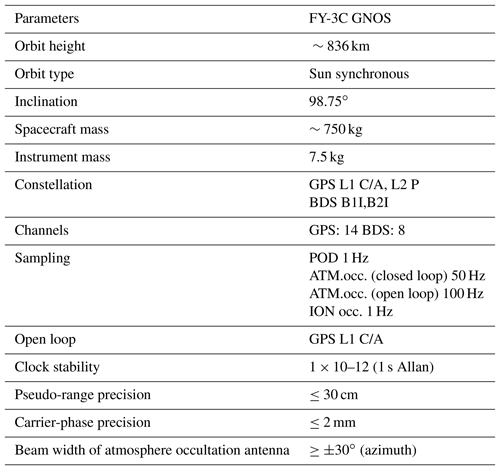
As a multi-GNSS receiver, GNOS has the ability to track up to eight GPS satellites and four BDS satellites for precise orbit determination (POD). In addition, it has velocity and anti-velocity antennas for simultaneously tracking a maximum of six and four occultations from GPS and BDS, respectively. Because of the presence of two antennas in opposite directions, both the rising and setting occultations can be retrieved. More instrumental details are given in the Table 1 and Bai et al. (2014). Currently, FY-3C GNOS GPS measurements can produce about 500 GPS-RO profiles per day for operational use in NWP systems, while GNOS from BDS signals are not yet operational and produce only about 200 profiles because of fewer reference satellites.
As with the pre-existing GPS-RO sounders, such as the GPS/Met (Global Positioning System/Meteorology) experiment (Ware et al., 1996), the COSMIC (Constellation Observing System for Meteorology, Ionosphere, and Climate; Anthes et al., 2008) and the European MetOp/GRAS (GNSS Receiver for Atmospheric Sounding) mission (Von Engeln et al., 2009), the raw observations from GNOS consist of phase and signal-to-noise ratio (SNR) measurements. In addition, auxiliary information provided by the International GNSS Service (IGS), such as the GPS precise orbits, clock files, Earth orientation parameters and the coordinates and measurements of the ground stations, are also needed. The IGS ultra rapid orbit products, with an approximate accuracy of 10 cm in orbit, are chosen for near-real-time operational use. The low Earth orbit (LEO) precise orbit determination (POD) can be estimated by integrating the equations of celestial motion (Beutler, 2005) using Bernese software Version 5.0 (Dach et al., 2007). The single difference technique is applied to obtain the excess phase as a function of time in an Earth-centred inertial reference frame. The Radio Occultation Processing Package (ROPP) software (Version 6.0), developed by the EUMETSAT ROM SAF (Radio Occultation Meteorology Satellite Application Facility), is used to determine different atmospheric parameters (Culverwell et al., 2015). One-dimensional variational (1D-Var) analysis, using background information from a T639L60 global forecast model, is used to retrieve temperature and humidity profiles. The T639L60 is a Chinese global medium-range weather forecast system, which became operational at CMA in 2009. However, since early 2017, some changes have been implemented in the operational stream. We obtain the auxiliary files through an ftp server in near real time provided by EUMETSAT GSN service, improving the timeliness to within 3 h. In addition, the POD software was replaced by the PANDA (Positioning And Navigation Data Analyst), which is developed originally by Wuhan University, China (Shi et al., 2008).
It is known that GPS signal SNR falls with decreasing altitudes, especially for the L2 frequency. Montenbruck (2003) and Larsen et al. (2005) tried to use a high-quality single-frequency approach to process atmospheric radio occultations without the degraded L2 signal but had limitations in the condition of high ionospheric oscillations. A dual-frequency approach for atmosphere radio occultation is still essential. Gorbonov et al. (2005) developed an indicator to estimate the quality of L2 signal in the low atmosphere and use it to judge where it needs to linearly extrapolate the difference of L1 and L2 signal. Zeng et al. (2016) investigates the optimal height for the extrapolation of L1–L2 by modelling the ionospheric bending angle using an approximate expression. These methods are successfully applied for CHAMP (CHAllenging Minisatellite Payload), COSMIC, MetOp and other missions. However, the degradation of the GNOS L2 had a large impact on the retrieval quality when the measurements were processed with ROPP. ROPP includes a preprocessing step in order to correct degraded L2 data. The approach is based on Gorbunov et al. (2005, 2006). The old approach in ROPP requires the L2 penetrating down to 20 km at least. It is hard for GNOS to get the entire L2 signal down to 20 km. The reason for GNOS losing L2 signal tracking is that GNOS has a lower SNR compared to other missions. Additionally, the GNOS antenna is smaller and not well located on the satellite. Consequently, we have to use additional cables, which results in a larger decrease in SNR than expected. Therefore, we developed and tested a new L2 bending angle extrapolation method for GNOS data and implemented them in ROPP.
In this paper, we will describe the new processing of GNOS data that reduces the large stratospheric biases in bending angle and refractivity and present a quality control scheme for FY-3C GNOS. These results will be useful for understanding the statistical error characteristics and quality control of the GNOS data and, more generally, the extrapolation approach may be useful for other missions where one signal is lost early.
The ROPP software (Culverwell et al., 2015) is used to retrieve atmospheric parameters, such as bending angle, refractivity, dry temperature, temperature and humidity, from GNOS excess phase measurements. The geometrical optics approach (e.g. Kursinski et al., 1997) is used to process the L1 and L2 phase delays to bending angle space above 25 km, and the Canonical Transform 2 (CT2) (Gorbunov and Lauritsen, 2004) technique is used for both L1 and L2 signals below 25 km. The combined statistical optimization ionospheric correction method (Gorbunov, 2002) produces “optimized” bending angles that are subsequently used in an Abel transform to produce refractivity profiles. We note that most NWP centres assimilate either bending angle or refractivity profiles.
In the preliminary assessments for the FY-3C GNOS GPS RO refractivity retrievals against NWP with the original ROPP processing system, it was found that the most obvious and prominent quality issue was the large departure biases, in the vertical range of 5–30 km, peaking at around 20 km (Fig. 1). The percentage of profiles affected was about 13 %–15 %. This bias problem is not seen with other RO missions and it was found to be related to GNOS GPS L2 signal tracking problems and the subsequent extrapolation of the L2 signal. It was found that most of the bad GNOS cases are rising occultations. To improve the tracking in the lower troposphere and the quality of rising occultations, open loop tracking is implemented for GNOS GPS L1 signal but not for L2 (Ao et al., 2009). In general, SNR falls under the complicated atmospheric conditions in the troposphere because of atmospheric defocusing. The GPS L2 signal is modulated by a pseudo-random precision ranging code (P code) for the purpose of anti-spoofing. Although GPS L2 can be demodulated using the semi-codeless method, it will be at the expense of SNR and precision (Kursinski et al., 1997). Therefore, the performance of L2 signal tracking is not as good as that of L1, especially for the rising occultations. Figure 2 shows the lowest straight line tangent altitude (SLTA) percentages of L1 and L2 signals, for both the rising and the setting occultations. It shows that the lowest tracking height of L1 C/A of both the rising and setting measurements are reasonable (Sokolovskiy, 2001), with more than 98.5 % profiles having an SLTA that is below zero . However, for the L2P, only 70 % of the rising measurements reach below 20 km. There is a total of 24.8 % of rising profiles that stop in the range of 20–70 km and 5.2 % that stop above 70 km, effectively meaning they contain no valid measurements. In contrast, 89.9 % of setting occultations can get below 20 km, which is better than the rising but about 10 % stop above that height. Those profiles that have bad L2 signal observations significantly affect the retrievals when using ROPP software to process the GNOS data.
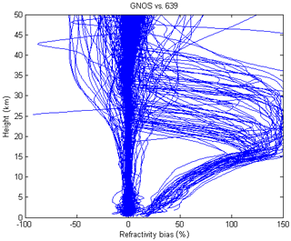
Figure 1FY-3C GNOS GPS refractivity bias compared to T639 (the Chinese forecast model data) on 28 January 2017 with 489 samples.
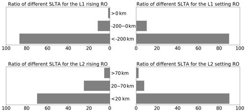
Figure 2Ratio of different SLTA of the L1 C/A and L2 P for the rising and setting occultations. The statistical result is from 28 January to 2 February 2017.
Figure 3 shows an example of GNOS performance in terms of excess phase, SNR and bending angle for two bad cases where the L2 stops early. In these two cases, there are no valid L2 excess phase observations below 25 or 30 km SLTA, respectively. However, there are L2 bending angles, extending to the near surface because of extrapolation within ROPP. Figure 4 is the same as Fig. 3 but for two good cases where the L2 measurements get to 20 km SLTA. Compared with the bad cases, the retrieved bending angles of L1, L2 and corrected LC span a similar vertical interval and show good agreement even at the lower part of the profiles.
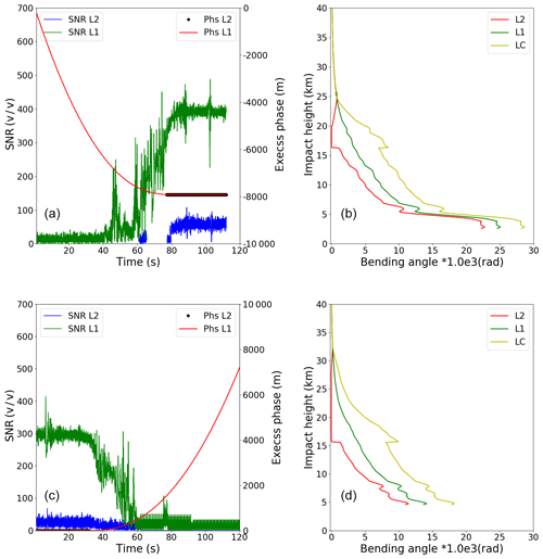
Figure 3Two bad cases – (a) a rising profile (FY3C_GNOSX_GBAL_L1_20170128_0332_AEG15_MS.NC) and (b) a setting profile (FY3C_GNOSX_GBAL_L1_20170128_0850_AEG18_MS.NC). Example L1 (red) and L2 (black) SNR and excess phase measured data. The resulting L1 bending angle (green), L2 bending angle (red) and corrected LC bending angle (yellow) profiles as a function of impact parameter computed using ropp_pp routines.
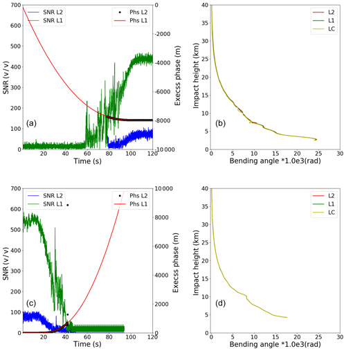
Figure 4Two good cases – (a) an arising profile (FY3C_GNOSX_GBAL_L1_20170128_1138_AEG27_MS.NC) and (b) a setting profile (FY3C_GNOSX_GBAL_L1_20170128_1648_AEG31_MS.NC). Example L1 (red) and L2 (black) SNR and excess phase measured data. The resulting L1 bending angle (green), L2 bending angle (red) and corrected LC bending angle (yellow) profiles as a function of impact parameter computed using ROPP routines.
ROPP includes a preprocessing step designed to correct degraded L2 data. The approach is based on Gorbunov et al. (2005, 2006) and is used successfully for other GPS-RO missions. Briefly, smoothed L1 and L2 bending angle and impact parameters are computed. An impact height, “PC”, above which the L2 data are considered reliable, is estimated using an empirical “badness score”. The empirical badness score at time t, is defined as follows:
where δp2 is a measure of the width of the L2 spectrum, and are the L1 and L2 impact parameters, respectively, computed from smoothed time series Δpa=200 m and Δpb=150 m (see also Eq. 11 of Gorbunov et al., 2006, for a slightly modified form). The largest Q(t) value in the impact height interval between 15 to 50 km is stored as the badness score for the occultation, potentially for quality control purposes.
The mean L1 and L2 bending angle and impact parameters are then computed in a 2 km impact parameter interval directly above PC. Simulated L2 bending angles and impact parameters are computed by adding the mean (L2–L1) differences to both the L1 bending angle and impact parameter values, using the data in the 2 km interval. Simulated L2 and L1 phase values are then computed from these bending angles. Corrected L2 excess phase values are computed by merging the observed L2 phase above PC, with the simulated values below PC, using a smooth transition over 2 km, centred on PC. The corrected L2 phase values are subsequently used in the wave optics processing of the L2 signals.
A specific difficulty with the GNOS processing is related to determining the impact height PC, used for both the computation of the mean L1 and L2 differences, and defining the transition between observed and modelled L2 phase values. Although the badness score is used to determine PC, PC also has a maximum value (20 km). This is defined as the wave optics processing height (25 km) minus a 5 km “safety border”. Therefore, the mean bending angles and impact parameters used in the L2–L1 correction can only be computed in a 2 km interval up to a maximum impact height of 22 km. Unfortunately, this is not high enough for GNOS L2 signals, with the result being that the mean L2–L1 bending angle and impact parameters computed in the 2 km interval above PC are corrupted, prior to the extrapolation.
As mentioned in the Sect. 2, some form of extrapolation of the observed L2 signal is required before it can be combined with the L1 signal, in order to remove the ionospheric contribution to the bending. However, the current L2 extrapolation implemented in ROPP leads to large bending angle and refractivity departures when processing GNOS RO data. Therefore, an alternative L2 extrapolation method has been implemented in the ROPP to solve the GNOS problem. The new approach is based on (unpublished) work by Culverwell and Healy (2015), who modelled the bending angles produced by a Chapman layer model ionosphere and established a basic theory for the relationship between fitting L1 and L2. A key underlying assumption in the L2 extrapolation approach is that the total bending angle can be written as a linear combination of the neutral bending plus a frequency-dependent ionospheric bending term. Therefore, we assume that subtracting the L1 bending angle from the L2 value at a common impact parameter removes the neutral bending contribution. This is a common assumption and is also made in the standard ionospheric methods used in GPS-RO (Vorob'ev and Krasil'nikova, 1994).
The extrapolation method adopted here is based on a “thin” ionospheric shell model, where the ionosphere approaches a delta function at a specified height (see Sect. 3.1, Culverwell and Healy, 2015). This ionospheric model is crude and it clearly would not be appropriate if we were attempting to retrieve ionospheric information. However, in the context of GNOS processing, we are mainly interested in modelling the impact of the ionosphere on bending angles with a tangent height well below the ionosphere, typically in the 25–60 km vertical interval. The neutral free L2–L1 bending angle differences in this interval vary slowly with height (impact parameter) (see Figs. 2 and 3 in Zeng et al., 2016). For example, adding a sporadic E layer near 100 km would not change the shape of the L2–L1 difference curve below 60 km significantly. Conversely, we cannot retrieve any E Layer information from the L2–L1 differences below 60 km.
Thus, for a vertically localized region of refractivity, well above tangent points of interest, the ionospheric contribution to the bending angle, α, at frequency, f, can be simply expressed by (Eq. 2.6, Culverwell and Healy, 2015):
where x=nr is product of the refractive index, n, and radius value, ra, is the impact parameter, m3 s−2 and ne is the electron number density. Commonly, the electron number density can be expressed in terms of the vertically integrated total electron content, TEC, which is defined as TEC = ∫nedr. The equation above can be simplified by assuming a very narrow ionospheric shell and written as follows (Eq. 3.2, Culverwell and Healy, 2015):
r0 is height of the peak electron density, which is assumed to be 300 km above the surface in this work.
The GPS L1 and L2 frequency bending angle difference is expressed as follows:
If we define , then,
In this work we estimate xso from a least-squares fit based on observed L1 and L2 bending angle differences produced with geometrical optics over a 20 km vertical above the lowest valid L2 bending angle value. The maximum height of the vertical interval is limited to 70 km. In theory, for a spherically symmetric ionosphere, xso should be proportional to the ionospheric TEC because the L2–L1 differences should be proportional to the TEC. However, we are not trying to retrieve the TEC here, and the quality of the TEC estimates has not been assessed. We simply estimate the parameter xso in order to extrapolate the L2–L1 differences below 25 km using a reasonable, physically plausible curve.
We currently assume the delta function ionospheric model peaks at 300 km above the surface. Experiments testing the sensitivity of the extrapolated bending angles to changes in the peak height from 250 to 350 km, in 10 km increments, have been performed. The largest differences between the 250 and 350 km experiments are about 1 micro-radian near the surface (figure is not shown). To put this in some context, the corrected bending angle value at an impact height of 20 km is typically 1600 micro-radians, and the neutral bending grows exponentially towards the surface with the density scale height (∼7 km). Therefore, the sensitivity to the assumed peak height is low.
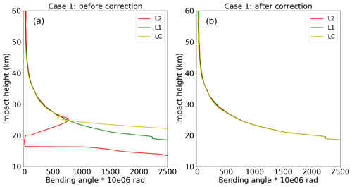
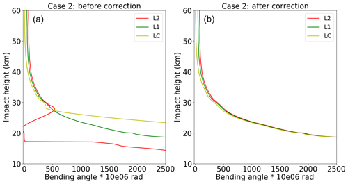
Figure 5Case 1 – the bending angle of L2 (red), L1 (green) and LC (yellow) before (b) and after (a) correction.
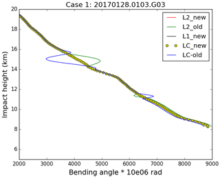
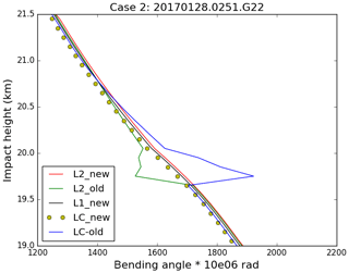
Two bad profiles, where the L2 signal stops above 20 km SLTA, have been chosen for demonstrating the extrapolation method. Their detailed information is listed in Table 2. Because the ionospheric effect becomes smaller in relative terms with decreasing height, the magnitude of the relative L2–L1 bending angle differences gets smaller with height. Seen from the direct comparisons between the new and the old extrapolation results of case 1 (Figs. 5 and 6), L2 bending angles are very different from the L1 bending angles before correction. After applying the new extrapolation approach, the L2 bending angles below 20 km are consistent with both L1 and LC bending angles. It is concluded that a more reliable LC bending angle can be obtained by using the new L2 extrapolation approach than the original L2 extrapolation method implemented in ROPP.
Clearly, using the new simple ionospheric model for the L2 extrapolation performs very well for the bad profiles with large biases. It is also useful to demonstrate the new extrapolation method for normal cases. Here the normal profiles are defined as the lowest SLTA reaching below 20 km, and the standard deviation with respect to the reanalysis refractivity data is within 2 % from the surface to 35 km. Therefore, two good profiles (Table 3) are selected to test the new extrapolation.
Generally, the new extrapolation method does not degrade the good profiles. In fact, the new method smooths some occultation points and improves the consistency of L1 and L2, as shown in Figs. 7 and 8, for example.
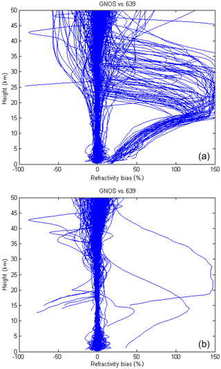
An alternative way to demonstrate the accuracy of the different extrapolation methods is to compare their refractivity retrievals with the forecast model data. A day worth of data are used to test the new L2 extrapolation method. Figure 9 shows that the new method can effectively eliminate ∼90 % of the problematic “branches” with the large percentage of refractivity errors often exceeding 100 %. In this plot, eight profiles still have a large bias after the new extrapolation because the L2 SLTA stops above 70 km, which is out of the processing range used in the extrapolation (below 70 km). These cases can be removed by using a simple quality control (QC).
Based on the GPS RO error sources and characteristics, many internal QC methods have been proposed in the literature. For example, the COSMIC Data Analysis and Archive Center (CDAAC) define an altitude, Z, below which a low quality of L2 signal has been detected. The maximum difference of Ll and L2 bending angle above Z and the ionospheric scintillation index analysed from the amplitude of L1 signal at high altitudes are used in the QC (Kuo et al., 2004). Gorbunov (2002) proposed a QC procedure in terms of the analysis of the amplitude of the RO data transformed by the Canonical Transform (CT) or the Full Spectrum Inversion (FSI) method (Gorbunov and Lauritsen, 2004), which is useful to catch the corrupted data because of phase lock loop failures. Beyerle et al. (2004) also suggested a QC approach to reject the RO observations degraded by ionospheric disturbances based on the phase delay of L1 and L2 signals. Zou and Zeng (2006) use the bi-weight check, removing large departure data from the statistical point of view. More recently, Liu et al. (2018) introduced a local spectral-width-based quality control, which improves the application in lower troposphere. The quality indicator badness score in ROPP is successfully applied for CHAMP, COSMIC, MetOp and other observations. However, just like the failure of processing GNOS data, the badness score is not adequate for identifying the GNOS data. The reason might be related to the empirical parameters (see Eq. 1). These parameters are formed based on the performances of CHAMP, COSMIC and MetOp missions, the L2 signals of which are not degraded as much as GNOS. Considering the new L2 extrapolation method and the characteristics of GNOS data, we introduce a new indicator to detect the poor-quality profiles based on the noise estimate of the L1 and L2 fit.
4.1 Noise estimate of the L1 and L2 fit
As noted earlier, as a result of L2 signal tracking problems, around 15 % profiles are degraded with the old processing. After applying the new L2 extrapolation method, most of them can be effectively corrected. As seen from Eq. (5), the key to the correction is how well the retrieved parameter, xso, fits the difference of L1 and L2 bending angles in the 20 km fitting interval. Currently, 25 km or the minimum L2 SLTA is the lower limit of the fitting interval.
We have introduced a new parameter, θα, to test the quality of the least-squares fit in the 20 km interval. It can be expressed as follows:
where Δα is the difference of L1 and L2 bending angles and the sum is over the n (L2–L1) values in the 20 km fitting interval. The parameter θα is the root mean square of the difference between the fitting model and (L2–L1) values. Clearly, it provides information about how well we are able to fit the L2–L1 bending angle differences with the model in a fitting interval where we trust the data. We assume that if the fitting model can reproduce the L2–L1 bending angle differences accurately in the fitting interval, we can then use the retrieved parameter xso to extrapolate the L2–L1 differences below 25 km to produce reasonable ionospheric corrected bending angles used for NWP applications.
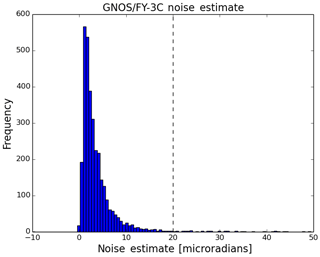
A histogram of the θα values has been obtained by accumulating statistics over a 7 d period (Fig. 10), and we use this to determine a QC threshold value as 20 micro-radians. Clearly, the 20 micro-radian threshold is empirical, but it can be related to the assumed bending angle error statistics used in the assimilation of GNSS-RO data. At ECMWF, the assumed bending angle uncertainty is 1.25 % from around 10 km to ∼32 km and 3 micro-radians above this height. This translates into around 7.5 micro-radians at 26 km, increasing to around 20 micro-radians at 20 km. The 20 micro-radian threshold is designed to screen out cases where the L2–L1 extrapolation could introduce significant additional errors. In summary, in the operational GNOS processing if the value of the θα is greater than 20 micro-radians the profiles will be rejected.
4.2 Mean phase delays of L1 and L2
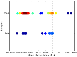
The θα QC parameter does not detect all the poor-quality profiles, and we need additional quality control methods to identify them. We find that it is also necessary to monitor the performance of GNOS mean L1 and L2 phase delays in the height interval of 60 to 80 km because this can also indicate the observational quality of GPS RO data. However, the L1 and L2 SNR values, which are commonly used as a QC indicator, are not found to be useful for identifying the large bias cases of GNOS data. For the rising profiles, the absolute accumulated phase delay should increase with height. Despite reasonable SNR above the height of 60 km, in some cases the mean phase delays have small values, leading to problems in the inversions. Figures 11 and 12 show the histograms of the L1 and L2 mean delay phase in rising occultations. They show that there is a clear separation of the mean phase delays. To clarify the quality of the two groups of samples, we identify them as “good” or “bad” profiles. The criterion for good or bad is that the mean bias relative to the background data is smaller than or greater than 2 % at the height interval of 10 to 40 km, respectively. Figures 13 and 14 demonstrate the distribution of L1 and L2 mean phase delay. Different colours represent different overlap density, dark blue is the lowest density and dark red is the highest. The colours between them represent increasing density. The good samples gather around −8000 m, while the bad samples accumulate around −100 m. Therefore, we can identify most of the bad rising occultations, when both L1 and L2 absolute mean phase values are smaller than 150 m. This threshold value is empirical considering the amount of the samples. Unavoidably, a small number of good profiles could be wrongly detected as well and few bad ones could be missed.
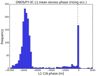
Figure 11The histograms of L1 mean excess phase for the rising occultation at the height of 60–80 km SLTA using 7 d of data from 16 to 22 February 2017.
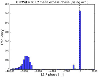
Figure 12The histograms of L2 mean excess phase for the rising occultation at the height of 60–80 km SLTA using 7 d of data from 16 to 22 February 2017.
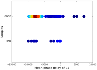
Figure 13The L1 mean phase delay (m) versus the good and bad samples. Different colours represent different overlap densities, dark blue is the lowest and dark red is the highest, the colours between them show gradually higher density.
4.3 The statistical performance of the applied QC methods
After checking a number of QC parameters, we use the following three QC tests:
-
if the occultation is rising and the absolute mean phase delays of L1 and L2 are both smaller than 150 m, the profile will be identified as bad;
-
if the value of θα is greater than 20 micro-radians, the profile will be identified as bad;
-
if the lowest SLTA of L2 is greater than 50 km, the profile will be identified as bad.
These have been tested using 3 months of data as to whether they can identify the good or bad large bias cases. The criterion for good or bad is similar to those mentioned above: whether the mean bias relative to the background data is smaller than or greater than 2 % at the height interval of 10 to 40 km.
A total of 41 928 samples were collected from 1 April to 30 June 2018. There are 38 752 good profiles and 3176 bad profiles evaluated by background data (e.g. the ECMWF reanalysis). The QC scheme applied in this paper identifies 37 627 good profiles and 4301 bad ones. According to statistics, the number of profiles that can be accurately identified is 36 957, the accuracy rate is 95.4 %, the number of missed is 1795, the missed rate is 4.6 %, 670 are misjudged and the false positive rate is 1.8 %. See Table 4 for clarification. Unavoidably, a small number of good profiles could be wrongly detected as well and few bad ones could be missed. In general, the performance of this kind of QC method can effectively identify most of the bad profiles.
This section demonstrates the performances of the comparison between the observational GNOS bending angles and the simulated ones using ECMWF short-range forecast data. GNOS bending angle profiles are those which are carried out using the new L2 extrapolation and quality control mentioned in Sects. 3 and 4, respectively. The period is from 6 July to 2 August 2018. The ECMWF data used as the background is the state-of-the-art short-range forecast data with 137 vertical levels extending from the surface to 0.01 hPa. Using the 2-D bending angle forward operator, ECMWF forecast data can be projected into the bending angle space at the GNOS locations.
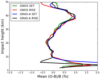
Figure 15Global bending angle departure results, as a function of impact height for the mean bias. The green, red, blue and black lines are representative of setting occultation for GNOS, rising occultation for GNOS, setting occultation for GRAS-A and rising occultation for GRAS-A. O is observation and B is background.
GNOS observations are provided in BUFR format for NWP applications, with the bending angles given on 247 vertical levels from the surface to 60 km. To provide a context for the comparisons, MetOp-A GRAS profiles from the same period are also selected as a benchmark. Figure 15 displays the mean bias for the GNOS and GRAS bending angle profiles both separated into rising and setting occultations, showing that GNOS and GRAS are very consistent with each other above 10 km. Figure 16 shows the standard deviation of the bending angle departures for the GNOS and GRAS. Their standard deviations are about 1 % between 10 and 35 km, increasing to about 12 % at 50 km and more than 15 % below the 5 km impact height. It is clear that the GNOS standard deviations are comparable to GRAS in the 10–40 km interval. The difference in the 20 to 25 km interval is related to the transition from wave optics to geometric optics for the GNOS. Generally, the two datasets have similar error characteristics in terms of both the mean bias and standard deviation over most of the height interval but especially in the GPS-RO core range between 10 and 35 km. The standard deviations of the GNOS departures below 10 km are smaller than the GRAS statistics. However, we do not believe that this indicates that GNOS data are superior to GRAS below 10 km. In general, GRAS measurements tend to penetrate more deeply in the troposphere, and this will affect the statistical comparison with GNOS. Furthermore, the difference between the setting and rising GRAS statistics is known but not fully understood, but this is an area of current investigation. Nevertheless, we believe that Figures 15 and 16 provide evidence that the GNOS and GRAS measurements have similar performance in the “core region” as a result the processing and QC methods introduced here.
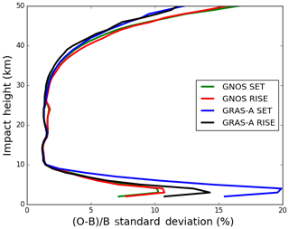
Figure 16Global bending angle departure results, as a function of impact height, for the standard deviation. The green, red, blue and black lines are representative of setting occultation for GNOS, rising occultation for GNOS, setting occultation for GRAS-A and rising occultation for GRAS-A. O is observation and B is background.
Note that further GNOS occultation departure statistics, including comparisons with other GPS-RO measurements in bending angle space, are now routinely available from the ROM SAF web pages. See http://www.romsaf.org/monitoring/matched.php (last access: 30 April 2019).
This study has focused on three main areas. Firstly, we have developed and tested a new L2 extrapolation for GNOS GPS-RO profiles. Secondly, we have investigated a QC method for GNOS after applying the new L2 extrapolation. Thirdly, we have estimated the bending angle departure statistics by comparing GNOS and ECMWF short-range forecast data. The main results are summarized below.
We have identified and investigated the GNOS GPS-RO cases that fail quality control with large bending angle departures, after the processing with the ROPP software. These large departures can be attributed to the GPS L2 signal tracking problems for signals that stop above 20 km in terms of SLTA and the related L2 extrapolation. The percentage of the profiles with a large departure is about 13 %–15 %. Therefore, we focused on a better L2 extrapolation for GNOS when the L2 signal stops early. A new L2 extrapolation approach has been implemented in ROPP to mitigate the problem. (These modifications will be available in ROPP 9.1; see http://www.romsaf.org/ropp/, last access: 30 April 2019) The main procedure is in bending angle space, and it is based on the (unpublished) study of Culverwell and Healy (2015). The new method can effectively remove about 90 % of the large departures. The remaining poor cases are mostly due to the L2 being completely missing.
We have studied and established the quality control method suitable for GNOS GPS-RO profiles after correcting the large departures. The new L2 extrapolation θα value can be taken as a QC parameter to evaluate the performance of the extrapolation. It is the root mean square of the difference between the fit and observations above the extrapolated height. The 20 micro-radian threshold is used to judge the good or bad profile after implementing the new L2 extrapolation method. The mean phase delays of L1 and L2 in the tangent height interval of 60 to 80 km are analysed and applied in the QC as well. The lowest SLTA of L2 is also set as a threshold to identify the bad profiles. Using the parameters mentioned above, the QC method can correctly identify 95.4 % of the profiles.
Finally, we have assessed the quality of the GNOS bending angles after implementing the new processing and QC by comparing with the background bending angles computed from the operational ECMWF forecasts. GRAS profiles from the same period are selected as a benchmark. The departure statistics for the GNOS and GRAS bending angle profiles in terms of the mean bias and standard deviations are similar at most of the heights, especially in the GPS-RO core region between 10 and 35 km.
As a result of this work, the GNOS data are now assimilated in operational NWP systems at, for example, the European Centre for Medium-Range Weather Forecasts (ECMWF), Deutscher Wetterdienst (DWD) and the Met Office.
Raw data of observed FY3C GNOS included in this paper can be accessed via http://satellite.nsmc.org.cn/PortalSite/Data/Satellite.aspx?currentculture=en-US (Zhang et al., 2019).
ML performed most of the data processing and analysis. SH worked on the ionospheric extrapolation method and produced Figs. 15 and 16. PZ provided expertise on the FY-3C and FY-3D GNOS instruments.
The authors declare that they have no conflict of interest.
This work was undertaken as part of a visiting scientist study funded by the Radio Occultation Meteorology Satellite Application Facility (ROM SAF), which is a decentralized processing centre under the European Organisation for the Exploitation of Meteorological Satellites (EUMETSAT).
We have to express our appreciation to Christian Marquardt for his valuable suggestions with respect to the RO processing and QC methods. In addition, we want to thank Ian Culverwell and Chris Burrow for their discussions. Finally, we would like to thank the fund support of National Key R & D Program of China (no. 2018YFB0504900) and Special Fund for Meteorology Research in the Public Interest (no. 201506074).
This paper was edited by Joanna Joiner and reviewed by four anonymous referees.
Anthes, R. A., Ector, D., Hunt, D. C., Kuo, Y.-H., Rocken, C., Schreiner, W. S., Sokolovskiy, S. V., Syndergaard, S., Wee, T.- K., Zeng, Z., Bernhardt, P. A., Dymond, K. F., Chen, Y., Liu, H., Manning, K., Randel, W. J., Trenberth, K. E., Cucurull, L., Healy, S. B., Ho, S.-P., McCormick, C., Meehan, T. K., Thompson, D. C., and Yen, N. L.: The cosmic/formosat-3 mission: Early results, B. Am. Meteorol. Soc., 89, 313–333, 2008.
Ao, C. O., Hajj, G. A., Meehan, T. K., Dong, D., Iijima, B. A., Mannucci, J. A., and Kursinski, E. R.: Rising and setting GPS occultations by use of open-loop tracking, J. Geophys. Res., 114, D04101, https://doi.org/10.1029/2008JD010483, 2009.
Bai, W. H., Sun, Y. Q., Du, Q. F., Yang, G. L., Yang, Z. D., Zhang, P., Bi, Y. M., Wang, X. Y., Cheng, C., and Han, Y.: An introduction to the FY3 GNOS instrument and mountain-top tests, Atmos. Meas. Tech., 7, 1817–1823, https://doi.org/10.5194/amt-7-1817-2014, 2014.
Beutler, G.: Methods of Celestial Mechanics, Springer-Verlag, Berlin, Heidelberg, New York, Germany, USA, ISBN 3-211-82364-6, 2005.
Beyerle, G., Wickert, I., Schmidt, T., and Reigber, C.: Atmospheric sounding by GNSS radio occultation: An analysis of the negative refractivity bias using CHAMP observations, J. Geophys. Res., 109, D01106, https://doi.org/10.1029/2003JD003922, 2004.
Culverwell, I. D. and Healy, S. B.: Simulation of L1 and L2 bending angles with a model ionosphere, ROM SAF Report 17, available at: http://www.romsaf.org/general-documents/rsr/rsr_17.pdf (last access: 30 April 2019), 2015.
Culverwell, I. D., Lewis, H. W., Offiler, D., Marquardt, C., and Burrows, C. P.: The Radio Occultation Processing Package, ROPP, Atmos. Meas. Tech., 8, 1887–1899, https://doi.org/10.5194/amt-8-1887-2015, 2015.
Dach, R., Hugentobler, U., Fridez, P., and Meindl, M.: Bernese GPS Software Version 5.0. Astronomical Institute, University of Bern, Bern, Switzerland, 2007.
Gorbunov, M. E.: Ionospheric correction and statistical optimization of radio occultation data, Radio Sci., 37, 17-1–17-9, https://doi.org/10.1029/2000RS002370, 2002.
Gorbunov, M. E. and Lauritsen, K. B.: Analysis of wave fields by Fourier Integral Operators and their application for radio occultations, Radio Sci., 39, RS4010, https://doi.org/10.1029/2003RS002971, 2004.
Gorbunov, M. E, Lauritsen, K. B., Rodin A., Tomassini, M., and Kornblueh, L.: Analysis of the CHAMP Experimental Data on Radio-Occultation Sounding of the Earth's Atmosphere, Izvestiya, Atmos. Ocean. Phys., 41, 726–740, 2005.
Gorbunov, M. E., Lauritsen, K. B., Rhodin, A., Tomassinin M., and Kornblueh, L.: Radio holographic filtering, error estimation, and quality control of radio occultation data, J. Geophys. Res., 111, D10105, https://doi.org/10.1029/2005JD006427, 2006.
Kuo, Y.-H., Wee, T.-K., Sokolovskiy, S., Rocken, C., Schreiner, W., Hunt, D., and Anthes, R. A.: Inversion and error estimation of GPS radio occultation data, J. Meteorol. Soc. Jpn., 82, 507–531, 2004.
Kursinski, E. R., Hajj, G. A., Hardy, K. R., Schofield, J. T., and Linfield, R.: Observing Earth's atmosphere with radio occultation measurements, J. Geophys. Res., 102, 23429–23465, 1997.
Larsen, G. B., Syndergaard, S., Høeg, P., and Sørensen, M. B.: Single frequency processing of Ørsted GPS radio occultation measurements, GPS Solut., 9, 144–155, https://doi.org/10.1007/s10291-005-0142-x, 2005.
Liu, H., Kuo, Y.-H., Sokolovskiy, S., Zou, X., Zeng, Z., Hsiao, L.-F., and Ruston, B. C.: A quality control procedure based on bending angle measurement uncertainty for radio occultation data assimilation in the tropical lower troposphere, J. Atmos. Ocean. Tech., 35, 2117–2131, 2018.
Montenbruck, O.: Kinematic GPS positioning of LEO satellites using ionosphere-free single frequency measurements, Aerospace Sci. Tech., 7, 396–405, 2003.
Shi, C., Zhao, Q., and Lou, Y.: Recent development of PANDA software in GNSS data processing, Proc. SPIE, 7285, 231–249, 2008.
Sokolovskiy, S. V.: Tracking tropospheric radio occultation signals from low Earth orbit, Radio Sci., 36, 483–498, 2001.
Von Engeln, A., Healy, S., Marquardt, C., Andres, Y., and Sancho, F.: Validation of operational GRAS radio occultation data, Geophys. Res. Lett., 36, L17809, https://doi.org/10.1029/2009GL039968, 2009.
Vorob'ev, V. V. and Krasil'nikova, G. K.: Estimation of the accuracy of the atmospheric refractive index recovery from doppler shift measurements at frequencies used in the NAVSTAR system, USSR Phys. Atmos. Ocean, 29, 602–609, 1994.
Ware, R., Rocken, C., Solheim, F., Exner, M., Schreiner, W., Anthes, R., Feng, D., Herman, B., Gorbunov, M., Sokolovskiy, S., Hardy, K., Kuo, Y., Zou, X., Trenberth, K., Meehan, T., Melbourne, W., and Businger, S.: GPS sounding of the atmosphere from lower Earth orbit: preliminary results, B. Am. Meteorol. Soc., 77, 19–40, 1996.
Yang, J., Zhang, P., Lu, N.-M., Yang, Z.-D., Shi, J.-M., and Dong, C.-H.: Improvements on global meteorological observations from the current Fengyun 3 satellites and beyond, Int. J. Digit. Earth, 5, 251–265, 2012.
Zeng, Z., Sokolovskiy, S., Schreiner, W., Hunt, D., Lin, J., and Kuo, Y.-H.: Ionospheric correction of GPS radio occultation data in the troposphere, Atmos. Meas. Tech., 9, 335–346, https://doi.org/10.5194/amt-9-335-2016, 2016.
Zhang, P., Lu, Q., Hu, X., Gu, S., Yang, L., Min, M., Chen, L., Xu, N., Sun, L., Bai, W., Ma, G., and Xian, D.: The latest progress of Chinese meteorological satellite program and core data processing technologies, J. Adv. Atmos. Sci., https://doi.org/10.1007/s00376-019-8215-x, in press, 2019.
Zou, X. and Zeng, Z.: A quality control procedure for GPS radio occultation data, J. Geophys. Res., 111, D02112, https://doi.org/10.1029/2005JD005846, 2006.


