the Creative Commons Attribution 4.0 License.
the Creative Commons Attribution 4.0 License.
Monitoring the differential reflectivity and receiver calibration of the German polarimetric weather radar network
John Hubbert
It is a challenge to calibrate differential reflectivity ZDR to within 0.1–0.2 dB uncertainty for dual-polarization weather radars that operate 24∕7 throughout the year. During operations, a temperature sensitivity of ZDR larger than 0.2 dB over a temperature range of 10 ∘C has been noted. In order to understand the source of the observed ZDR temperature sensitivity, over 2000 dedicated solar box scans, two-dimensional scans of 5∘ azimuth by 8∘ elevation that encompass the solar disk, were made in 2018 from which horizontal (H) and vertical (V) pseudo antenna patterns are calculated. This assessment is carried out using data from the Hohenpeißenberg research radar which is identical to the 17 operational radar systems of the German Meteorological Service (Deutscher Wetterdienst, DWD). ZDR antenna patterns are calculated from the H and V patterns which reveal that the ZDR bias is temperature dependent, changing about 0.2 dB over a 12 ∘C temperature range. One-point-calibration results, where a test signal is injected into the antenna cross-guide coupler outside the receiver box or into the low-noise amplifiers (LNAs), reveal only a very weak differential temperature sensitivity (<0.02 dB) of the receiver electronics. Thus, the observed temperature sensitivity is attributed to the antenna assembly. This is in agreement with the NCAR (National Center for Atmospheric Research) S-Pol (S-band polarimetric radar) system, where the primary ZDR temperature sensitivity is also related to the antenna assembly (Hubbert, 2017). Solar power measurements from a Canadian calibration observatory are used to compute the antenna gain and to validate the results with the operational DWD monitoring results. The derived gain values agree very well with the gain estimate of the antenna manufacturer. The antenna gain shows a quasi-linear dependence on temperature with different slopes for the H and V channels. There is a 0.6 dB decrease in gain for a 10 ∘C temperature increase, which directly relates to a bias in the radar reflectivity factor Z which has not been not accounted for previously. The operational methods used to monitor and calibrate ZDR for the polarimetric DWD C-band weather radar network are discussed. The prime sources for calibrating and monitoring ZDR are birdbath scans, which are executed every 5 min, and the analysis of solar spikes that occur during operational scanning. Using an automated ZDR calibration procedure on a diurnal timescale, we are able to keep ZDR bias within the target uncertainty of ±0.1 dB. This is demonstrated for data from the DWD radar network comprising over 87 years of cumulative dual-polarization radar operations.
- Article
(1738 KB) - Full-text XML
- BibTeX
- EndNote
Dual-polarization (dualpol) weather radars have become the standard in European weather radar networks. Typically, national weather service radars operate in the STAR mode (simultaneous H and V transmit and H and V receive), sometimes referred to as SHV (simultaneous H and V) mode. Polarization moments, such as differential reflectivity (ZDR), can be used to better characterize the hydrometeors (Seliga and Bringi, 1976; Straka et al., 2000; Schuur et al., 2012; Al-Sakka et al., 2013; Steinert et al., 2013) and to better quantify the precipitation amount (e.g., Bringi and Chandrasekar, 2001; Ryzhkov et al., 2005; Bringi et al., 2011; Diederich et al., 2015). Dualpol moments are also used to improve the data quality control via fuzzy-logic clutter classifiers (Werner and Steinert, 2012; Hubbert et al., 2009, 2010a).
In order to keep biases in quantitative precipitation estimates under 20 %, ZDR should be calibrated to an accuracy of better than ±0.2 dB (Seliga and Bringi, 1976; Bringi and Chandrasekar, 2001), assuming no bias in reflectivity (Z). In order to quantify the bias in ZDR, the differential gains and losses of both the H and V transmit and H and V receive paths need to be assessed as well as the differential transmit power. Active components in the H and V receive paths, such as the LNAs (low-noise amplifiers), are never perfectly matched and are temperature dependent and thus are a possible source of time-varying ZDR bias. The differential gain of the entire signal path has to be quantified and removed from the measured ZDR in order to obtain an accurate estimate of intrinsic ZDR. The most well-established way to calibrate ZDR is via vertically pointing scans in light rain (Gorgucci et al., 1999; Bringi and Chandrasekar, 2001). The premise is that the rain particles are polarimetrically isotropic when viewed vertically so that ZDR is 0 dB. This technique works well since it is an end-to-end measurement that takes into account both the transmit and receive paths, and the radar resolution volume is filled with distributed scatterers. Another technique to calibrate ZDR is to characterize the transmit and receive paths of the radar with RF (radio frequency) sources and power meters (Hubbert et al., 2008; Zrnic et al., 2006). However, it has been found that such estimates can have large uncertainty, and thus research radars such as CSU-CHILL and S-Pol employ the vertically pointing technique to attain a reliable ZDR calibration. The engineering technique has also proved challenging for the Next-Generation Radars (NEXRADs; Ice et al., 2014).
In Hubbert (2017) the cross-polar power technique for ZDR calibration is applied to data from NCAR's dual-polarimetric S-band radar, S-Pol. In contrast to most operational radars, S-Pol uses a fast switch to alternate between H- and V-only transmit polarizations on a pulse-to-pulse basis. Both H and V polarizations are received, thus providing measurements of the cross-polar signal, which is not measured in STAR mode. S-Pol is operated without a radome, and the receiver is located in a container which is temperature controlled. The DWD radars have antenna-mounted receiver electronics and operate within a radome. In Hubbert (2017) systematic ZDR temperature dependence was found using an analysis of solar scan data, cross-polar measurements and transmit power monitoring. It was shown that the temperature-dependent gain of antenna assembly caused the observed ZDR biases. Frech et al. (2013) also investigate the characteristics of a DWD antenna in part using solar measurements. The antenna characteristics for H and V polarizations must match very well, not only during the acceptance of a system but also during subsequent day-to-day operations. For example, because of mechanical stress over time, the feed horn could defocus which may result in increased side-lobe levels and increased beam squint. This in turn would affect the clutter suppression performance and the interpretation of ZDR in areas with large reflectivity gradients. Furthermore, antenna cross coupling must be small in order to avoid additional ZDR bias (Wang et al., 2006; Hubbert et al., 2010b; Zrnic et al., 2010).
In order to both calibrate and monitor the ZDR bias, DWD radars employ a vertically pointing scan (sometimes called birdbath scans) executed every 5 min. DWD has successfully applied this method in rain, mixed-phase precipitation and solid-phase precipitation. For systems that are not able scan at a 90∘ elevation angle, ZDR bias is evaluated in specific precipitation situations. The evaluation of ZDR in Bragg-scatter areas is another potential ZDR monitoring method which is, however, mainly suitable for S-band systems (e.g., Richardson et al., 2017).
ZDR monitoring methods that use solar radiation are now commonly employed in operational weather radar networks (Huuskonen and Holleman, 2007; Holleman et al., 2010; Figueras i Ventura et al., 2012; Frech, 2013; Huuskonen et al., 2016; Frech et al., 2019). The sun can be considered an unpolarized source of radiation (i.e., the H and V powers are equal) also emitting at radar frequencies. Solar radiation can also be used to calibrate the receive path gain as well as the navigation position of a radar system. These techniques use solar spikes that are observed during normal operational scanning and thus can be continuously carried out without interrupting the radar operations. Though the solar method only calibrates the receive path of a radar system, this method is considered an essential element in monitoring ZDR. It is complementary to the birdbath method which relies on the presence of precipitation above the radar site.
In this paper the ZDR monitoring methods that are employed across the DWD weather radar network, which consists of 17 radar systems, are described. In the course of operating this radar network since 2009, a ZDR temperature dependence has been found and documented (Frech, 2013). A goal of this paper is to identify the source of this ZDR temperature dependence. Similar to Hubbert (2017), solar scans are employed for a systematic analysis using the Hohenpeißenberg research radar (Frech et al., 2017). Each solar scan takes about 4 min and is repeated every 10 min. Up to 90 scans are available to assess the diurnal ZDR variability due to temperature. The pseudo ZDR antenna patterns based on the solar scans are compared to a ZDR antenna pattern measured during a dedicated antenna pattern measurement (Frech, 2013). Antenna beamwidths derived from the solar scans are compared to the beamwidths measured during the antenna pattern measurements. The diurnal variation in solar differential power S is used to assess the operational ZDR monitoring results from birdbath scans and S measurements derived from solar interferences extracted from operational data. This analysis is complemented with results from continuous one-point-calibration data, where a test signal is injected either in the antenna coupler (before the TR limiter) or just before the low-noise amplifier (LNA) by using a built-in test signal generator (TSG).
The S temperature dependence is also investigated in terms of antenna gain which is determined from solar power measurements at the C-band (Sirmans and Urell, 2001). This also provides an insight into how well the two receiver chains are calibrated. Those gain estimates are compared to four operational radar sites, where one full diurnal cycle of solar box scans was acquired per site. The performance of the operational ZDR calibration of the radar network based on birdbath measurements is discussed. This analysis is based on a combined 87 years of radar operation. In addition, based on the operational monitoring, an example of an unusual failure of a TR limiter is shown. The main findings are summarized in the conclusions.
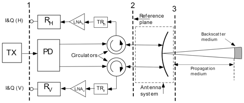
Figure 1A general block diagram of the DWD radar systems. TX refers to the transmitter; PD is the power divider, and TRh,v are the TR limiters in the H and V receive paths. I&Q denotes the plane where the received analog signal at the intermediate frequency (IF) is digitized in the IFD (intermediate frequency digitizer).
Given in Fig. 1 is a radar block diagram that captures the essential components affecting ZDR. The vertical dashed lines mark measurement planes that are useful for defining the various gains and powers of the radar.
where TXH,V are the transmit powers measured at plane 2, are the H and V antenna gains, and RXH,V are the H and V receiver gains from plane 2 to plane 1. The differential gains are defined as
so that the ZDR bias (also referred to as the ZDR offset) can be written as
in linear form, and in dB as
The ZDR offset is determined using a birdbath scan. The key assumption of the method is that ZDR is 0 when looking vertically at falling precipitation. A deviation from 0 dB is then attributed to a ZDR offset or bias. The differential bias in the ΔRX path can be due to differential receiver gain, circulator attenuation, and LNAs and other electronics in H and V electronic paths. Offset in ΔTX is primarily a function of the power divider circuitry and the circulators. All of these components have temperature-dependent gains. The differential offset due to ΔA is due to uncertainties in the antenna characterization (H and V antenna gain, width of the main lobe) and antenna temperature (we will discuss this later).
ZDR bias estimated from a birdbath scan is computed as a range-averaged ZDR in the antenna far field (starting at about a 700 m range). Threshold requirements are ρhv>0.9 (copolar correlation coefficient; Bringi and Chandrasekar, 2001), SQI >0.5 (signal quality index or normalized coherent power1) and at least 10 valid range bins (25 m length each) in a ray. Then the median ZDR is computed from all rays of the sweep. In order to obtain the diurnal-averaged ZDR, the median ZDR from all birdbath scans of a given day is computed. A median ZDR is computed only if there are at least six birdbath scans available with valid data. There is no further separation according to the hydrometeors as the method is also applicable to mixed-phase and solid-phase precipitation (e.g., Dixon et al., 2018).
The automated procedure to adjust the ZDR offset on a diurnal bias has been implemented. If the offset ΔTX,RX is properly set initially on a given day, we have
where ΔTX,RX is the static offset which is stored as an initial parameter in the signal processor and is the current diurnal ZDR value determined from the birdbath scan. ΔTX,RX is a value that has been determined during routine maintenance.
If the following is found at a given day ti,
then the offset needs to be adjusted. The nonzero ZDR offset is now
In order to calibrate ZDR, the initial ZDR offset is corrected. The new system offset is then
The correct ZDR offset is stored in the metadata set of every ODIM HDF5 sweep that is sent to the central DWD radar data processing site. As part of centralized quality control, this offset is applied to the ZDR data prior to any product generation. The corrected offset is valid until a new ZDR offset can be computed from birdbath data. Depending on the season, weeks may pass until the next precipitation event that can be used to assess the ZDR offset occurs. In principle there could be drifts in the ZDR bias which would introduce a ZDR bias during a dry period. However our experience indicates that the radar hardware state is sufficiently stable and precipitation is frequent enough so that the mean ZDR bias over a day would be smaller than 0.1 dB in these dry periods. This is further discussed in Sect. 8.
In this section the configuration and setup of the solar box scans is described. The scanning azimuth and elevation limits of a box scan are 8∘ and 5∘, respectively, centered on the position of the sun at the beginning of the scan. The scan takes about 4 min to complete and is scheduled every 10 min. During this time the scan box azimuth and elevation limits are not adjusted to account for the movement of the sun; however, in the postcollection analysis of the data, the movement of the sun is corrected by using the ray time tag from which the position of the sun is determined. The radar operates with a pulse length of 0.8 µs (0.4 µs), with a scan rate of 2∘ s−1 (0.1∘ s−1) and a PRF (pulse repetition frequency) of 800 Hz (1600 Hz). The elevation angle increment is 0.1∘. The range resolution is set to 250 m, and data up to a range of 150 km are acquired.
The system is transmitting while scanning, and the PRF is chosen such that the system is operated with a constant duty cycle. It is important that the transmitter operates while making solar scans so that the radar components of the transmit and receiver paths are in an operational state.
The integrated solar powers are corrected for noise. Prior to each solar scan, the thermal background noise is estimated at the elevation of the sun and about 30∘ off the azimuth of the sun. Overcast situations do not bias the solar scans. In the analysis the signal-to-noise ratios SNRh and SNRv (horizontal and vertical, respectively), the cross-correlation coefficient ρhv, and the differential solar power S (stored as ZDR) are used. All data moments are computed from unfiltered time series (no Doppler clutter filter is applied). To avoid ground clutter contamination, only data beyond a 50 km range are used; however, at low-elevation angles data beyond a 50 km range can be contaminated by clutter. If this is the case, those data are removed from the analysis.
The standard lightning protection of a radar system consists of four vertical lightning poles in the vicinity of the radome which extend above the highest point of the radome. For the Hohenpeißenberg radar system, prior the measurements used in this study, three of the four lightning poles were removed in order to avoid disturbance of the radar data due to the lightning protection hardware.
Solar data analysis
Solar box scan data analysis is described in this section. The analysis of solar box scans employs the methods that are used to evaluate solar interferences (sun spikes) from operational scans (Huuskonen and Holleman, 2007; Frech, 2013). The methods are extended to compute the antenna beamwidth from the solar scan (Huuskonen et al., 2014). The computed antenna beamwidth calculated from a solar box scan is a proxy since the solar disk (0.53∘) is convolved with the antenna pattern (0.9∘ beamwidth) measurement, and thus the observed solar disk and antenna pattern are smeared in azimuth and elevation. However, the beamwidth estimated from the solar scan is very close to the classic antenna pattern measurements (Frech et al., 2013). The results are shown in the next section. The positioning error and beam squint are also computed from this approach. The results related to positioning error are discussed in a companion paper (Frech et al., 2019). In order to determine the differential solar power bias of the receiver chain, the differential solar power is integrated over a 1∘ solid angle (±0.5∘ relative to the beam center).
The calibration of the receiver (dBm0) can be verified by comparing the measured solar power with independent solar power measurements. The solar flux measurements are available daily (2–3 times) from the Dominion Radio Astrophysical Observatory (DRAO) in Canada (Tapping, 2001). The solar flux measurement is monitored at a wavelength of λ=10.7 cm (S-band) with an expected accuracy of 1 sfu (solar flux unit; Tapping, 2013). This corresponds to a 0.02 dBm accuracy of the power measurement. This is the independent flux measurement which is used to monitor the absolute receiver sensitivity of our radar system. As a first step, the S-band solar flux has to be converted to the corresponding C-band flux. Parameterizations of solar C-band flux as a function of the S-band flux are documented in the literature (e.g., Holleman et al., 2010).
with F10.7 denoting the adjusted solar flux (in sfu) from DRAO (an sfu has units of 10−22 W (m2 Hz)−1). The maximum measured received solar power needs to take into account the receiver bandwidth Δf and the effective antenna area Ae. Ae is defined as m2, where an antenna efficiency of η=0.55 is assumed (Sirmans and Urell, 2001). The electrical diameter of the antenna de is 4.27 m.
The solar power at the C-band, psun in mW, can be written as
For the C-band system at Hohenpeißenberg the receiver bandwidth Δf≈1.38 MHz (for 0.8 µs; for 0.4 µs Δf≈2.52 MHz). The factor of 0.5 is introduced since the solar flux is an unpolarized source, whereas the radar system receives power at horizontal or vertical polarization.
The solar power is determined from the measured peak SNR that is estimated from the solar scan.
The solar power in H and V can be written as
where Agas denotes the gaseous attenuation, dBm0h,v is the minimum detectable power of the receiver and k is the beamwidth correction factor. For the Hohenpeißenberg radar the minimum detectable power is dBm and dBm for a pulse length of 0.8 µs. Those power levels are determined as part of the engineering radar calibration.
Before the measured solar power Ph,v can be related to the received solar power, a correction for the one-way gas attenuation, Agas, of the solar power due to the earth's atmosphere has to be applied. This is estimated using a 4∕3 earth's radius model, where the ray path r up to the top of the atmosphere is approximated using a standard atmosphere (e.g., Holleman et al., 2010):
The gaseous attenuation can be approximated as
with z0 denoting the equivalent height of a homogeneous atmosphere. A homogeneous atmosphere is defined by constant air density with height. Using typical values of a standard atmosphere, the height of a homogeneous atmosphere is z0≈8.4 km. For a we assume a=0.008 dB km−1.
The peak solar SNR determined from the box scan requires a beamwidth correction factor k because the solar disk is smaller than the antenna beamwidth (Sirmans and Urell, 2001):
with θs=0.57∘ and θ3 dB≈0.9∘. This yields k=1.14 dB.
In order to assess the differential power bias in the entire receive path, the solar measurements can be used.
where SH,V are H and V solar powers estimated from scanning the sun. Since the sun is an unpolarized source of radiation, intrinsic differential solar power, S, should be 0 dB. Thus, a measurement of nonzero differential solar power indicates a ZDR offset caused by differential losses and gains in the receive path.
From the computed solar powers a differential power S is defined as
All moments and power estimates at ranges larger than 50 km are averaged, and the results given in the next sections show range-averaged data.
One way to compare the solar power measurements from DRAO with radar-estimated solar power is to compute the antenna gain (Sirmans and Urell, 2001). The 3 dB beamwidth and the geometric and electric antenna dimensions are known. Furthermore, a constant antenna efficiency is assumed when computing Ae. The antenna gain is defined as (Sirmans and Urell, 2001)
with the radar wavelength λ. Using Eq. (12) we can write this as
We compute two gain values, first using the independent data from DRAO to compute psun and secondly computing psun using Eq. (13). A difference between those two gain estimates using the independent solar power measurements at the C-band and the radar-measured solar power can be interpreted as a receiver calibration bias and thus a bias of dBm0h,v. The antenna efficiency η is fixed in both gain estimates. The advantage of using gain as a retrieval parameter instead of the solar flux (as is commonly done in the literature, where the radar-measured received solar power is converted into solar flux units) is that the time variability in the solar flux is removed. So differences in gain estimates using solar power measured by radar and the independent gain estimate based on DRAO data provide straightforward information on a relative receiver calibration bias. Furthermore, one can easily compare results from different pulse widths and different radar systems. Since basic antenna parameters are fixed, the gain estimates cannot be viewed as true antenna gain estimates.
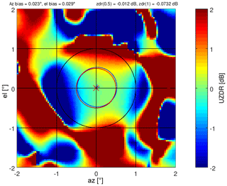
The typical solar beam plots for the SNRh and SNRv patterns are shown in Fig. 2. The corresponding differential solar power S pattern and the cross-correlation coefficient ρhv are shown in Fig. 3.
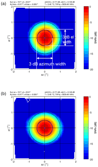
Figure 2Typical SNR solar beam plot from a box scan, showing SNRh (a) and SNRv (b). These plots illustrate how the solar beamwidths are computed. On top of each panel, the corresponding position of the sun relative to the radar, the computed elevation (el) and azimuth (az) radar positioning bias, the transmit frequency, the radome temperature, and the ZDR integrated over 0.5 and 1∘ radii is given as a standard information data set with this product. The red and blue crosses indicate the azimuth and elevation bias for the two polarizations.
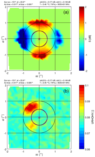
Figure 3The corresponding pattern of differential solar power S is shown in panel (a) (to be compared with Fig. 2). The cross-channel correlation coefficient is shown in panel (b) (denoted as URHOHV on the color scale label). Note the narrow scale from 0 to 0.1.
There are four areas of large differential powers at a radii of 1∘ (Fig. 3). This differential solar power S pattern is supported by analyzing the 3 dB beamwidth employing the method of Huuskonen et al. (2014). The time series of 3 dB beamwidths from 91 solar box scans are shown in Fig. 4, and the corresponding azimuth and elevation of the sun during that day are shown in Fig. 5. We show the series in order to illustrate the consistency of the results throughout a day for different elevations and azimuths. The mean azimuth width is 0.94∘ ± 0.01∘ and 0.98∘ ± 0.01∘ for H and V, respectively. The elevation width in H and V is 0.95∘ ± 0.006∘ and 0.89∘ ± 0.006∘, respectively.
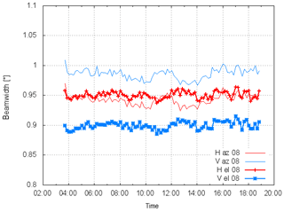
Figure 4Time series (UTC) of 3 dB beamwidths from 91 solar box scans. Data are taken on 23 June 2018. Shown are the beamwidths in vertical and horizontal dimensions and for horizontal and vertical polarizations.
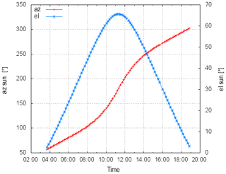
Figure 5The diurnal cycle (time in UTC) of the elevation and azimuth positions of the sun (23 June 2018) which correspond to the solar box scans that are used to compute the beamwidths in Fig. 4.
The beamwidth results indicate a near-circular beam shape in H, and in contrast, the beam shape is more elliptical in V. The superposition of the circular and elliptical beam shapes leads to the observed solar ZDR or S pattern.
During the Hohenpeißenberg acceptance tests a series of antenna pattern measurements were carried out (Frech et al., 2013). An example S pattern is shown in Fig. 6. The dynamic range of an antenna pattern measurement is of course much larger (peak SNR of the external source is 68 dB compared to the peak solar SNR of about 7 dB), so there is differential power visible outside the main beam. But within the main beam (±1∘) the S patterns show a remarkable agreement. Thus, the main lobe of solar S patterns can be used to assess the antenna performance without carrying out dedicated antenna pattern measurements. Taking such a measurement on a regular basis throughout the lifetime of a radar system (≈20 years) helps to monitor the state of the antenna assembly.
The complex H and V time-series data resulting from scanning the solar disk can also be used to create a cross-channel correlation antenna pattern. The simultaneously received voltage time series from a single dwell angle, Vh(i) and Vv(i), for the horizontal and vertical channels, respectively, are correlated as
where N is the number of samples. Thus gives the pointwise (spatial) correlation from temporal averages. These correlation data from all dwell angles are interpolated to a grid. The resulting magnitude of the correlation product of Eq. (21) is shown in Fig. 3b. If solar radiation is unpolarized, the correlation of data between any two orthogonal receive polarization channels is zero by definition. The correlation magnitude in Fig. 3b shows two principal lobes in the two left quadrants where the correlation increases. These two areas of increased correlation coefficient are manifestations of the antenna polarization errors (Hubbert et al., 2010a, b). This signature is present throughout nearly all of the solar box scan measurements.
Over 2157 solar box scans were made in order to study the variability in S. Before a statistical analysis is performed on these data, two illustrative S time series from 2 particular days are shown. The example from 3 June 2018 is shown in Fig. 7. The mean differential solar power S is −0.19 dB, and over the day the standard deviation is 0.032 dB. The standard deviation was determined after the removal of the trend using a 5th order polynomial. In addition two temperature measurements are shown. One is termed the radome temperature which indicates the temperature in the radome to which the antenna assembly is exposed. The LNA (low-noise amplifier) temperature is a temperature reading close to the LNAs within the receiver box which is assumed to be representative for the temperature condition within the receiver box. By eye there seems to be a correlation between temperature and S. From similar data gathered on 15 June 2018 in Fig. 8, this correlation appears more obvious. S increases by about 0.2 dB over this day with a temperature increase of about 7 ∘C. For this case the mean S is −0.15 dB and the standard deviation is 0.038 dB. In principle we would expect a constant S throughout the day because the sun is an unpolarized source of radiation. So besides the obvious temperature dependence, the variability in S (expressed in terms of the standard deviation) may be caused by the radome, insufficient cross-polar isolation of the antenna and/or clutter, or just random sampling errors. There are no means of separating those effects with the existing measurements.
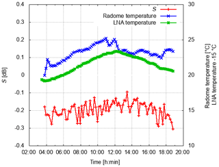
Figure 7Variability in differential solar power S (dB) on 3 June 2018 (UTC). Also shown is the radome temperature and the temperature near the LNA in the receiver box.
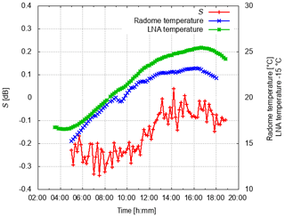
Figure 8Variability in differential solar power S [dB] on 15 June 2018 (UTC). Also shown is the radome temperature and the temperature near the LNA in the receiver box.
Next, the time series of S2 are compared to the operational monitoring results of differential solar power S2, which are based on solar interferences identified from the operational scanning data, and to ZDR data from birdbath scans (S is squared to make it comparable to ZDR). In order to compare S from box scans to the operational results, the system ZDR offset of −0.1 dB is subtracted from those data. There is only one S2 and ZDR value per day from operational monitoring, indicated by the two straight lines in Figs. 9 and 10, respectively. ZDR from the birdbath scans is only updated if there has been sufficient precipitation on the previous day. Otherwise the ZDR of the last precipitation event is assumed to be still valid.
There is on average a very good agreement between the S2 derived from operational scanning and the S2 from the box scans (Figs. 9 and 10). It is obvious that diurnal temperature variations cannot be captured by the S2 which is derived from operational scanning. The respective ZDR from the birdbath scan on 3 June is near 0 dB compared to −0.1 dB for S2 . The opposite is found on 15 June, when the birdbath ZDR is −0.1 dB and S2 is near 0 dB.
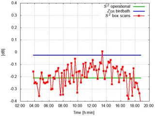
Figure 9S2 variability during 3 June 2018 (UTC) compared to the S2 and ZDR from operational monitoring. Operational data are updated once a day. No update of ZDR is possible if there has not been sufficient precipitation over the radar site on the previous day. In that case we keep the ZDR from the last precipitation event (here 1 June 2018).
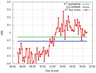
Figure 10S2 variability during 15 June 2018 (UTC) compared to the S2 and ZDR derived from operational monitoring. Operational data are updated once a day. No update of ZDR is possible if there has not been sufficient precipitation over the radar site on the previous day. In that case we keep the ZDR from the last precipitation event (here 13 June 2018).
The antenna gain is computed using the measured solar power by the radar and the DRAO solar flux (see Eq. 20). If the receive path is properly characterized and calibrated, the retrieved antenna gain should be the antenna gain as provided by the antenna manufacturer. If the solar power based on the DRAO data is used to compute the antenna gain using Eq. (20), a deviation from the gain value provided by the manufacturer is due to the assumptions made about the antenna characteristics. Similarly, by using the radar-measured solar power, a systematic deviation from the manufacturer gain is indicative of a calibration error.
The antenna gain results are shown in Figs. 11 and 12 for the same dates as before, where the time series of gain for both polarizations are shown as a function of the solar azimuth position. The antenna gain results (about 90 estimates based on 90 box scans) in Figs. 11 and 12 are compared to the gain estimate using the solar power derived from the operational monitoring and the gain estimate based on DRAO solar power data, for which there is just one value per day, indicated by the straight lines in Figs. 11 and 12. For both the 3 June and 15 June 2018 data, larger variability in gain on the order of 0.2 dB is observed in the morning and evening when the elevation of the sun is low. Most likely surface clutter is the prime contribution to this variation in gain. A decrease in gain on the order of 0.3 dB is observed during the day, followed by an increase in gain of about 0.3 dB in the evening hours.
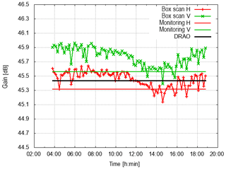
Figure 11Antenna gain time series in H and V during 3 June 2018 (UTC). Also shown is the antenna gain estimate from operational monitoring (monitoring H, monitoring V) and the gain estimate using DRAO data only.
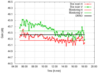
Figure 12Antenna gain time series in H and V during 15 June 2018 (UTC). Also shown is the antenna gain estimate from operational monitoring (monitoring H, monitoring V) and the gain estimate using DRAO data only.
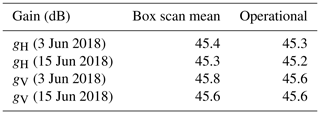
The antenna gain provided by the manufacturer is 45.4 dB in H and 45.2 dB in V. The average gain based on the box scan data in comparison to the gain based on the operational monitoring of solar hits is summarized in Table 1. Based on those measurements, there is a very good agreement between the gain estimates of H using solar power measured by radar and the manufacturer value of 45.4 dB.
Therefore, the assumptions about the antenna characteristics appear reasonable. The deviation is within 0.2 dB (considering the gain in V). The gain estimate from the solar box scans is about 0.3–0.4 dB larger in V than the estimate in H and the manufacturer gain. This suggests a receiver calibration bias on this order which indicates that the receive channel is actually more sensitive (meaning that dBm0 should be smaller by 0.3–0.4 dB).
Qualitatively, the diurnal variation in gain seems to suggest that there is a temperature correlation with a decrease in gain during the day as a function of temperature and an increase in gain at the end of the day when temperature deceases again (compare with the temperature variation for the 2 d shown in Fig. 13). This will be further investigated after analyzing the temperature dependence for the whole data set.
Table 1Mean antenna gain from box scan data compared to the gain obtained from the operational monitoring. Antenna manufacturer gain is 45.4 (H) and 45.2 dB (V); see also Frech et al. (2013). The DRAO-data-based gain estimate is 45.4 dB.
In this section it is shown that the temperature sensitivity of S in the end can be attributed to the antenna assembly. The S variability as a function of temperature is initially evaluated based on over 2157 solar box scans acquired in early summer 2018. The temperature references for S, the radome temperature and the receiver temperature are taken. The radome temperature is the temperature in the volume surrounded by the radome. There is constant ventilation so that well-mixed temperature conditions can be expected. The RX temperature is measured in the receiver box close to the LNA which is mounted on a solid metal plate.
The scatter plots of S versus radome temperature and LNA temperature are shown in Fig. 13. A temperature span of 12 ∘C is captured with this data set. It is apparent that the correlation of S and LNA temperature is better than the correlation with the radome temperature especially for radome temperatures between 22 and 24 ∘C. The bin-wise median of S(T) (bin width is 1∘) together with the first and third quartiles are shown in Fig. 13 with black lines. This implies that the origin of the S temperature dependence is maybe located in the receiver box, where the analog components for H and V obviously have a differential temperature dependence, though the correlation does not show cause and effect. This is examined more closely later. In Fig. 13b we fit a second-order polynomial to the −RX temperature data, with (dB∕T2), (dB∕T) and (dB). The fit to the curve resulting from the bin-averaged data is quite good.
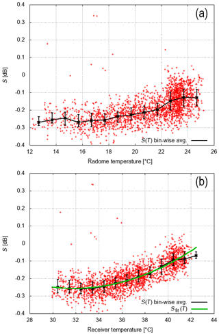
Figure 13S scatter plot as a function of radome temperature (a) and LNA temperature (b). LNA temperature is a good proxy for the temperature variations within the receiver box. Also shown is the bin-wise-average (S(T) bin-wise avg; 1∘ width and the first and third quartiles of all values within this bin) and a polynomial fit of second order (Sfit(T); see also text) of S versus LNA temperature (b). In total 2157 box scans are used for this analysis.
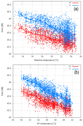
Figure 14Gain (H and V) scatter plot as a function of radome temperature (a) and LNA temperature (b). LNA temperature is a good proxy for the temperature variations within the receiver box. Also shown is the bin-wise-averaged gain (1∘ width and the first and third quartiles of all gain values within this bin) as a function of temperature. In total 2157 box scans are used for this analysis.
Similarly, Fig. 14 shows the dependence of solar-measured H and V gains on the receiver and radome temperatures. There is an obvious correlation of H and V gains with temperature. The best correlation appears if taking the receiver gain temperature as a reference (Fig. 14). If we use the bin-wise-averaged gain for H and V to compute the differential solar power S as gH−gV, we recover the curve shown in Fig. 13. The bin-wise-averaged gain and the resulting differential gain are shown in Fig. 15. We note the gains decrease by about 0.6 dB over a temperature difference of 10 ∘C, and this indicates a temperature-dependent bias of the radar reflectivity factor Z. This temperature dependence is an additional contribution to the overall uncertainty in calibration, which is usually not considered in error assessments from manufacturers, where commonly engineering uncertainties in measuring the antenna gain and the transmit and receive losses among others are considered.
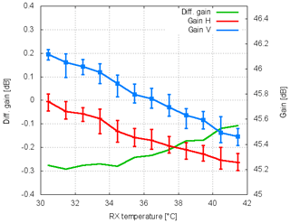
Figure 15Bin-wise-averaged gain (H and V; see Fig. 14) and computed as gH−gV versus receiver temperature.
The differential power and gain temperature dependence appear to correlate best with the receiver temperature, and thus the LNAs and associated circuitry could be responsible for the seen temperature-dependent S observations. In order to evaluate the LNA gains, single-point calibration measurements are employed. With the one-point calibration, a test signal is injected into the receive path using a built-in test signal generator. Since the response of the digital receiver is linear, the receiver response for a test signal above noise level and below the receiver saturation can be used to determine dBZ0 and dBm0. In order to investigate the temperature sensitivity, the one-point calibration was carried out every 5 min as part of the operational 5 min scan cycle. A test signal can be coupled to the H and V receive paths at the antenna cross-guide coupler or at the LNA inside the receiver box. A 3 dB power splitter provides nearly equal power levels for both channels. A small power difference is inconsequential in evaluating the temperature sensitivity of the differential gain of the LNAs. The H and V signal path from the antenna cross-guide coupler includes a waveguide filter, a circulator and a TR limiter, which are all located behind the antenna outside the antenna-mounted receiver box and also manifest some dependence on temperature (see Fig. 2 in Frech et al., 2017). The temperature stability of the built-in TSG was characterized in a climate chamber where a very small temperature-dependent power output of the TSG of ±0.05 dB within a temperature range between 0 and 30 ∘C was found. For proper calibration results, TSG losses between the coupler and the reference plane 1 (see Fig. 1) have been quantified using a network analyzer. The TSG losses between the antenna coupler and the reference plane 1 are measured as 77.96 dB (H) and 77.89 dB (V). If the TSG signal is injected at the LNA, the losses have been determined as 26.16 dB for both channels. Any observed temperature sensitivity based on the one-point calibration is therefore attributed to the respective receive paths. A data set with 2562 calibration results, where the TSG signal was coupled to the antenna cross-guide coupler, was acquired between 14 March 2019 and 23 March 2019. A second data set with 2810 calibration results, where the TSG signal was coupled to the LNAs, was acquired between 23 March and 5 April 2019.
The temperature-dependent measured power samples are shown in Fig. 16. The temperature dependence of both data sets is identical if either the receiver temperature or the radome temperature is used. Similar to the retrieved gain based on solar power, we find a 0.6 dB decrease over a comparable temperature range. The lower measured power levels in Fig. 16b are due to additional losses in the receive path. A remarkable feature of both independent data sets is the nonlinearity of the horizontal power sample at around 7 ∘C (radome temperature) or 19 ∘C (receiver temperature) with a ≈0.1 dB dip. This is not found for the power sample in V. The reason for this is still unknown. The corresponding differential power H–V is shown in Fig. 17. The nonlinearity in H leads to a −0.1 dB bias in differential power just for this specific part of the temperature range. For the rest of the temperature range only a very small temperature dependence in differential power up to 0.02 dB over a range of ≈16 ∘C is found. The differential power based on power samples where the TSG is coupled to the antenna cross-guide coupler is on the order of 0.2 dB. This significantly larger difference compared to the other data set can be attributed not only to different insertion losses of the TR limiters and the circulators but also to the uncertainty in the measured TSG losses. But more importantly, there is again a very small temperature dependence of differential power.
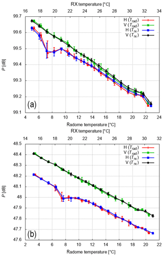
Figure 16Bin-wise-averaged H and V power measurements based on the one-point calibration. Either the radome (Trad) or the receiver box temperature (Trx) is used as a reference. Shown is the median and the first and third quartiles of 1∘ wide temperature bins. The results with the TSG coupled to the LNA (a) and to the antenna cross-guide coupler (b) are shown.
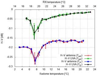
Figure 17Bin-wise-averaged differential power H–V based on the power samples from the one-point calibration. Either the radome (Trad) or the receiver box temperature (Trx) is used as a reference. Shown is the median and the first and third quartiles of 1∘ wide temperature bins.
This result is now compared to the S temperature dependence shown in Fig. 13. Even though the temperature ranges do not match precisely, some conclusions can be drawn. Based on solar box scan data a 0.2 dB increase in S over a temperature range of 12 ∘C is found. The correlation with temperature is best if the receiver temperature is used to determine the mean temperature dependence of S. In contrast, the temperature sensitivity of differential power based on the one-point calibration indicates a substantially smaller temperature dependence with an increase of 0.02 dB or less over a comparable temperature range (excluding the anomalous behavior at 7 or 19 ∘C). This behavior is essentially identical if either the radome temperature or the receiver temperature is used as a reference for the one-point-calibration results. Therefore, the temperature sensitivity observed in S can be attributed to the antenna assembly. There is one caveat however. There is a chance that the temperature dependence may be different in the two compared temperature ranges. This will be investigated in future measurements. This result is in agreement with the results in Hubbert (2017), who arrived at a similar conclusion. It is argued that the thermal expansion of the antenna assembly (including the struts) is responsible for a large part of the temperature sensitivity of differential power. This is still a matter of investigation, but initial simulations of antenna radiation patterns appear to support this conclusion. Details on the DWD antenna can be found in Frech et al. (2013).
Time series of the ZDR calibration since the beginning of 2013 are available. From the beginning ZDR was monitored using the birdbath scans and the solar interferences. How the ZDR values agree for specific days has been shown in the previous section. The success of the automated ZDR calibration procedure is discussed for all 17 radar sites up to September 2018 (Fig. 18). The methodology to determine ZDR is described in Sect. 2. In Fig. 18 each data point represents a diurnal-averaged ZDR value, which can only be determined if there are at least six birdbath scans available with precipitation. In total 16 646 diurnal-averaged ZDR values (which corresponds to 45 years of data) are shown in Fig. 18. The corresponding total radar operation time amounts to 31 928 d (about 87 years). There is on average sufficient precipitation present on 52 % of the days. So for a given day, there is precipitation over the site for at least six birdbath scans. The median ZDR is 0.0 dB, and the mean absolute deviation MAD is 0.029 dB (Wilks, 2011; Frech et al., 2017). This indicates that the method to update the ZDR offset once a day appears sufficiently robust to provide a well-calibrated ZDR. Further optimization is needed to eliminate the apparent outliers which may be caused by e.g., unwanted clutter contributions. Note that the diurnal variability in ZDR due to, e.g., temperature, as discussed in this paper, is not captured by this automated procedure to determine the ZDR offset. From one scan to another there might be deviations larger than 0.1 dB due to, e.g., temperature effects. The existence of larger ZDR deviations is also indicated by the data in Fig. 18. In addition, the median ZDR in nonoverlapping 5 d intervals is computed using the calibrated ZDR data from the whole network. There appears to be no annual variation in ZDR bias (Fig. 18), which is an indication that the method can be applied as a season-independent method without restricting the ZDR offset analysis to liquid precipitation only.
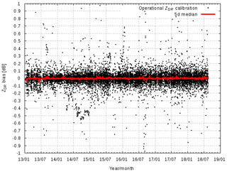
Figure 18Radar-network-wide-calibrated ZDR using birdbath data. Also shown is the median ZDR over a 5 d interval from January 2013 until September 2018. There is no systematic annual variation in ZDR, which implies that it is not necessary to distinguish the precipitation phase when calculating the ZDR from birdbath data.
Note that the radar systems have similar performance with respect to ZDR bias (Fig. 19). There is only one system (radar Neuhaus, ID 9) which sticks out. But even this system is within the target corridor of ±0.1 dB.
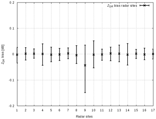
Figure 19ZDR bias of the 17 DWD radar sites, January 2013–August 2018. Shown is the median ZDR and the first and third quartiles.
The automated adjustment is well suited to correct for system drifts on a timescale longer than a day. This is shown in Fig. 20 for the Eisberg system. This is a case of an unusual TR limiter degradation of the Eisberg radar. TR limiters are usually located in front of the LNAs in order to protect the receiver from the transmit pulse (see Fig. 1). The transmit pulse causes the TR limiter to act as an open circuit for a short period of time called the recovery time. Typically an aging TR limiter shows an increase in its recovery time which causes an undesired attenuation of the received signal at ranges close to the radar but then extends in range. Here, the overall duration of attenuation of the TR limiter increased with time, which is illustrated by the fact that the S has a similar drift to the ZDR determined from the birdbath scan. Over a time period of 9 months there is an increase in ZDR bias of 3 dB. Since the increase in attenuation happens to be on a timescale longer than 1 d, the operational ZDR offset adjustment is able to keep ZDR within 0.2 dB (ZDR-calibrated 90∘, Fig. 20). After the replacement of the faulty TR limiter, the system operated reliably for about 3 months before the other limiter started to degrade in a similar way. Within about 9 months the ZDR bias increased to −4 dB. The ZDR bias is constant after the replacement of the TR limiter in October 2016. On the scale shown here, the ZDR bias, as estimated from the birdbath measurement, is well approximated by S. Since S is only a function of the receiver electronics and the antenna and the birdbath measurements are a function of the receiver electronics, the antenna gains squared and the transmit power (Eqs. 6 and 17, respectively) it can be concluded that the transmit power ratio at the reference plane is relatively constant. Diurnal variations in S due to temperature are not seen in this daily average data.
Similar cases have been observed at other radar sites. The reason for this type of TR limiter failure is not known yet. This example nicely illustrates the benefit of using and combining different data sources to monitor and calibrate ZDR.
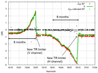
Figure 20TR limiter failure at the Eisberg radar. This illustrates the benefits of using solar monitoring and birdbath scans to assess biases in the receive path. Here, the combination of solar monitoring (solar power S) and birdbath analysis isolates the receive path as the source of the ZDR problem. In addition we show the resulting calibrated ZDR, where the calibration offset is determined from birdbath data automatically.
Considering the classic aging of a TR limiter, a prototype of an automated analysis of the shape, and in particular the slope of the ZDR profile has been implemented. Results are currently being analyzed. This approach will provide the height interval over which the mean ZDR should be computed from the birdbath profile. Another promising approach to monitoring the classic aging of a TR limiter is the monitoring of clutter power in close vicinity of the radar (Mathijssen et al., 2018).
Full diurnal cycles of solar box scans have been acquired from four operational identical radar systems: Flechtdorf, FLD (27 June 2018); Neuheilenbach, NHB (24 July 2018); Boostedt, BOO (27 June 2018); and Hanover, HNR (24 July 2018). The solar box scans were evaluated similarly to the Hohenpeißenberg (MHP) box scans. The resulting diurnal series of gain estimates for H and V as a function of the solar azimuth position are shown in Fig. 21. In addition, the MHP gain estimates from 3 June 2018 are shown for comparison. Aside from the Flechtdort gh, all gain estimates for both polarizations are within a 1 dB range and close to the nominal antenna gain of 45.4 dB. The diurnal variation in BOO shows a decrease in gain of up to 0.2 dB around a solar azimuth of 90 and 270∘. The decrease is more pronounced for the vertical than the horizontal polarization. This feature can be related to the presence of lightning poles outside the radome. This decrease is not visible for the other operational systems because the azimuthal position of the lightning poles is such that the elevation of the sun during the measurements is too high so that the poles are not in the field of view of the antenna. Similar to MHP, a slight decrease in gain in the course of a day by 0.2 dB is also found for systems HNR, FLD and BOO. Diurnal temperature variations are the likely cause for this. The nominal antenna gain based on antenna pattern measurements is about 45.4 dB. A retrieved gain value, gH, of close to 47 dB from FLD indicates a calibration error of 1.6 dB which can presumably be attributed to an erroneous characterization of the horizontal receive path.
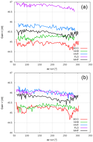
Figure 21Diurnal gain estimates as a function of solar azimuth from five radar systems, Boostedt (BOO), Flechtdorf (FLD), Hanover (HNR), Neuheilenbach (NHB) and Hohenpeißenberg (MHP). Shown is the gain of the horizontal receive channel (a) and vertical receive channel (b). The time series shown here are based on about 90 box scans that are available for each station.
Various practical aspects of calibrating and monitoring the calibration state of the DWD radars were investigated in this paper. Measurements of solar H and V powers are particularly useful in this endeavor since the solar radiation at the C-band can be considered unpolarized, and thus H and V solar powers incident on the radar antenna are equal. It follows that any differences from 0 dB in the ratio of the measured H and V solar powers (S, Eq. 17) indicate a ZDR bias caused by the radar's total receive path (antenna plus receiver hardware and electronics). Variations in S as a function of time provide insights into the sources of the previously observed temperature sensitivity of ZDR bias within the DWD weather radar network. To this end, over 2000 dedicated solar box scans measured with the DWD dualpol C-band research radar Hohenpeißenberg were used to investigate the variability in S. The Hohenpeißenberg radar system is identical to the 17 radar systems of the DWD network and is operated 24∕7 as an operational system if it is not being used for research purposes. The solar box scans were complemented by the analysis of differential power data from one-point-calibration measurements, which were carried out every 5 min as part of the operational 5 min scan cycle in spring 2019. Using a built-in TSG, test signals were coupled to either the antenna cross-guide coupler outside the receiver box at plane 2 (see Fig. 1) or into the LNAs inside the receiver box. Prior to those tests the temperature dependence of the power output of the TSG was assessed in a climate chamber. Over a 30 ∘C temperature range, power variations smaller than 0.05 dB were observed. Based on the solar box scans, a nonlinear temperature dependence of solar differential power S with a 0.2 dB increase in a temperature range between 15 and 25 ∘C was found. Differential power measurements based on one-point-calibration data indicate a temperature dependence of less than 0.02 dB over a comparable temperature range. This indicates that the S temperature sensitivity can be attributed to the antenna assembly. This is consistent with the analysis of Hubbert (2017). Thermal expansion of the antenna assembly, which includes the struts, seems to cause a major part of the observed temperature sensitivity of S. In order to avoid the observed S variability, the antenna assembly should be kept at a constant temperature or a correction factor based on the average functional relationship between S and T could be applied.
Solar box scans provide a simple and straightforward approach to assessing and monitoring antenna characteristics of a weather radar network. It is suggested that solar box scans can be used to monitor the antenna assembly throughout the lifetime of a radar system if the differential power variability in the receive electronics can be kept to a minimum (say 0.05 dB). With the DWD radar operation software, solar box scans can be scheduled remotely like an operational scan. Antenna beamwidths derived from the solar box scans also assist in detecting the degradation of antenna assembly. If the feed were out of focus2, a mismatch of the H and V beam could be discerned. The solar S antenna pattern agreed well with the ZDR antenna pattern that was measured during a standard antenna pattern measurement in 2011 during the installation phase of the radar system. It was shown that the differential H to V antenna pattern from the standard antenna pattern measurement matched the S pseudo antenna pattern well. The main H beam shape was circular, whereas the main V beam shape was slightly elliptical.
The antenna gain was estimated using the radar-measured solar power and the solar power based on the solar flux measurements of the Dominion Radio Astrophysical Observatory (DRAO) in Canada. If the receive path is properly characterized and calibrated, the retrieved antenna gain should match the antenna gain as provided by the antenna manufacturer. A systematic deviation is then indicative of a receiver characterization bias, and trends in gain may reflect a temperature influence related to the receive path. Not surprisingly, a differential temperature dependence of gain was found. The temperature sensitivity of the H and V gain was a linear decrease of 0.6 dB over a 10 ∘C temperature range, which directly relates to a radar reflectivity Z bias of 0.6 dB. Data from one-point-calibration measurements revealed a similar decrease in H and V gains. Thus, the temperature-dependent H and V gains can be directly related to the receiver electronic path. This contribution is typically not considered in the error budget of the radar equation and should be viewed as significant if the common target accuracy of ±1 dBZ is desired. Based on two case studies, the antenna gain based on the measured solar power is within 0.2 dB of the antenna gain provided by the antenna manufacturer. There is also very good agreement, within 0.2 dB, between the retrieved gain estimates based on operational solar monitoring and solar box scans.
A full diurnal cycle of solar box scans from four operational radar sites were compared to the Hohenpeißenberg data. With respect to gain, all sites were roughly within 1 dB in H and V. There was only one site where the retrieved gain indicated a bias of about 1.5 dB, which points to a calibration problem.
Results of the long-term operational ZDR calibration based on operational birdbath scans from the DWD radar network were given. It was shown that ZDR biases, which may occur on a timescale longer than 1 d, can be automatically corrected based on birdbath ZDR data. The analysis is based on over 87 years worth of radar data from the DWD radar network. A specific case with an unusual degradation of the two TR limiters during a time span of 2.5 years was shown. Even though significant ZDR bias was present, the ZDR calibration procedure was able to keep the ZDR bias within ±0.1 dB. This is because the increase in bias was slow and steady, on a timescale longer than 1 d. Using S data from the operational solar monitoring, the receive path could be identified as the source of the bias. Note that this is a rather unusual TR limiter behavior compared to a typical degradation of a TR limiter, where the recovery time usually increases, since the overall attenuation increased substantially. Within 9 months, the TR limiter attenuation increased to 4 dB.
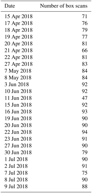
Table A1 gives an overview of the dates where typically full diurnal cycles of solar box scans were acquired with the MHP radar.
Data are available from the authors upon request.
MF carried out the data acquisition and performed the data analysis. JH wrote Sect. 2, provided the theoretical background in Sect. 2, and contributed to the analysis and interpretation of the results. MF prepared the manuscript.
The authors declare that they have no conflict of interest.
We acknowledge the fruitful discussions with the DWD radar team, in particular with Jörg Seltmann, Theo Mammen, Kay Desler, Norbert Engler, Bertram Lange and Benjamin Rohrdantz. The comments of the reviewers are greatly appreciated.
This paper was edited by Pavlos Kollias and reviewed by Martin Hagen and Richard Ice.
Al-Sakka, H., Boumahmoud, A.-A., Fradon, B., Frasier, S. J., and Tabary, P.: A new fuzzy logic hydrometeor classification scheme applied to the French X-, C-, and S-band polarimetric radars, J. Appl. Meteor. Climatol., 52, 2328–2344, 2013. a
Bringi, V. N. and Chandrasekar, V.: Polarimetric Doppler Weather Radar, Cambridge University Press, Cambridge, https://doi.org/10.1017/CBO9780511541094, 2001. a, b, c, d
Bringi, V. N., Rico-Ramirez, M. A., and Thurai, M.: Rainfall Estimation with an Operational Polarimetric C-Band Radar in the United Kingdom: Comparison with a Gauge Network and Error Analysis, J. Hydrometeor., 12, 935–954, 2011. a
Diederich, M., Ryzhkov, A., Simmer, C., Zhang, P., and Trömel, S.: Use of Specific Attenuation for Rainfall Measurement at X-Band Radar Wavelengths. Part I: Radar Calibration and Partial Beam Blockage Estimation, J. Hydrometeor., 16, 487–502, 2015. a
Dixon, M., Hubbert, J., and Ice, R.: ZDR calibration, in: 10th Europ. Conf. On Radar in Meteor. and Hydrol., short cource on ZDR calibration, available at: https://www.erad2018.nl/short-courses/ (last access: 1 March 2020), 2018. a
Figueras i Ventura, J., Boumahmoud, A.-A., Fradon, B., Dupuy, P., and Tabary, P.: Long-term monitoring of French polarimetric radar data quality and evaluation of several polarimetric quantitative precipitation estimators in ideal conditions for operational implementation at C-band, Q. J. Roy. Meteor. Soc., 138, 2212–2228, 2012. a
Frech, M.: Monitoring the data quality of the new polarimetric weather radar network of the German Meteorological Service, in: 36th AMS Conf. on Radar Meteorology, Breckenridge, CO, USA, p. 16, AMS, 2013. a, b, c, d
Frech, M., Lange, B., Mammen, T., Seltmann, J., Morehead, C., and Rowan, J.: Influence of a Radome on Antenna Performance, J. Atmos. Ocean. Tech., 30, 313–324, 2013. a, b, c, d, e
Frech, M., Hagen, M., and Mammen, T.: Monitoring the Absolute Calibration of a Polarimetric Weather Radar, J. Atmos. Ocean. Tech., 34, 599–615, https://doi.org/10.1175/JTECH-D-16-0076.1, 2017. a, b, c
Frech, M., Mammen, T., and Lange, B.: Pointing Accuracy of an Operational Polarimetric Weather Radar, Remote Sens., 11, 18 pp., https://doi.org/10.3390/rs11091115, 2019. a, b
Gorgucci, E., Scarchilli, G., and Chandrasekar, V.: A procedure to calibrate multiparameter weather radar using properties of the rain medium, IEEE T. Geosci. Remote Sens., 37, 269–276, 1999. a
Holleman, I., Huuskonen, A., Kurri, M., and Beekhuis, H.: Operational monitoring of weather radar receiving chain using the sun, J. Atmos. Ocean. Tech., 27, 159–166, 2010. a, b, c
Hubbert, J. C.: Differential Reflectivity Calibration and Antenna Temperature, J. Atmos. Ocean. Tech., 34, 1885–1906, 2017. a, b, c, d, e, f
Hubbert, J. C., Pratte, F., Dixon, M., and Rilling, R.: NEXRAD differential reflectivity calibration, in: 24th Int. Conf. on Interactive Information Processing Systems for Meteorology, Oceanography, and Hydrology (IIPS), 6B.6, AMS, available at: https://ams.confex.com/ams/88Annual/webprogram/Paper131167.html (last access: 1 March 2020), 2008. a
Hubbert, J. C., Dixon, M., Ellis, S. M., and Meymaris, G.: Weather Radar Ground Clutter. Part I: Identification, Modeling, and Simulation, J. Atmos. Ocean. Tech., 26, 1165–1180, https://doi.org/10.1175/2009JTECHA1159.1, 2009. a
Hubbert, J. C., Ellis, S. M., Dixon, M., and Meymaris, G.: Modeling, Error Analysis, and Evaluation of Dual-Polarization Variables Obtained from Simultaneous Horizontal and Vertical Polarization Transmit Radar. Part II: Experimental Data, J. Atmos. Ocean. Tech., 27, 1599–1607, https://doi.org/10.1175/2010JTECHA1337.1, 2010a. a, b
Hubbert, J. C., Ellis, S. M., Dixon, M., and Meymaris, G.: Modeling, Error Analysis, and Evaluation of Dual-Polarization Variables Obtained from Simultaneous Horizontal and Vertical Polarization Transmit Radar. Part I: Modeling and Antenna Errors, J. Atmos. Ocean. Tech., 27, 1583–1598, https://doi.org/10.1175/2010JTECHA1336.1, 2010b. a, b
Huuskonen, A. and Holleman, I.: Determining weather radar antenna pointing using signals detected from the sun at low elevations, J. Atmos. Ocean. Tech., 24, 476–483, 2007. a, b
Huuskonen, A., Kurri, M., Hohti, H., Beekhuis, H., Leijnse, H., and Holleman, I.: Radar Performance Monitoring Using the Angular Width of the Solar Image, J. Atmos. Ocean. Tech., 31, 1704–1712, https://doi.org/10.1175/JTECH-D-13-00246.1, 2014. a, b
Huuskonen, A., Kurri, M., and Holleman, I.: Improved analysis of solar signals for differential reflectivity monitoring, Atmos. Meas. Tech., 9, 3183–3192, https://doi.org/10.5194/amt-9-3183-2016, 2016. a
Ice, R., Heck, A., Cunningham, J., and Zittel, W.: Challenges of polarimetric weather radar calibration, in: 8th Europ. Conf. On Radar in Meteor. and Hydrol., available at: http://www.pa.op.dlr.de/erad2014/programme/ExtendedAbstracts/117_Ice.pdf (last access: 1 March 2020), 2014. a
Mathijssen, T., Broere, S., Beekhuis, H., and Leijnse, H.: Operational monitoring of T/R-Limiter degradation based on close range ground clutter, in: Proceeedings 10th Europ. Conf. On Radar in Meteor. and Hydrol., pp. 956–959, 2018. a
Richardson, L. M., Zittel, W. D., Lee, R. R., Melnikov, V. M., Ice, R. L., and Cunningham, J. G.: Bragg Scatter Detection by the WSR-88D. Part II: Assessment of ZDR Bias Estimation, J. Atmos. Ocean. Tech., 34, 479–493, https://doi.org/10.1175/JTECH-D-16-0031.1, 2017. a
Ryzhkov, A., Schuur, T., Burgess, D., Heinselman, P., Giangrande, S. E., and Zrnic, D. S.: The Joint Polarization Experiment. Polarimetric Rainfall Measurements and Hydrometeor Classification, B. Am. Meteorol. Soc., 86, 809–824, 2005. a
Schuur, T. J., Park, H.-S., Ryzhkov, A. V., and Reeves, H. D.: Classification of precipitation types during transitional winter weather using the RUC model and polarimetric radar retrievals, J. Appl. Meteor. Climatol., 51, 763–779, 2012. a
Seliga, T. A. and Bringi, V. N.: Potential Use of Radar Differential Reflectivity Measurements at Orthogonal Polarizations for Measuring Precipitation, J. Appl. Meteorol., 15, 69–76, https://doi.org/10.1175/1520-0450(1976)015<0069:PUORDR>2.0.CO;2, 1976. a, b
Sirmans, D. and Urell, B.: On Measureing WSR-88D Antenna Gain Using Solar Flux, Tech. rep., Radar Operations Center, Norman, Ok, 2001. a, b, c, d, e
Steinert, J., Werner, M., and Tracksdorf, P.: Hydrometeor classification and quantitative precipitation estimation from quality assured radar data for the DWD C-band weather radar network, 36th Conf. On Radar Meteor., 16–20 September 2013, Breckenridge, CO, USA, available at: https://ams.confex.com/ams/36Radar/webprogram/Handout/Paper228477/ams2013_poster363_steinert.pdf (last access: 1 March 2020), 2013. a
Straka, J. M., Zrnić, D. S., and Ryzhkov, A. V.: Bulk hydrometeor classification and quantification using polarimetric radar data: Synthesis of relations, J. Appl. Meteorol., 39, 1341–1372, 2000. a
Tapping, K.: Antenna calibration using the 10.7 cm solar flux, in: Workshop on Radar Calibration, Albuquerque, NM, AMS, 2001. a
Tapping, K. F.: The 10.7 cm solar radio flux (F10.7), Space Weather, 11, 394–406, https://doi.org/10.1002/swe.20064, 2013. a
Wang, Y., Chandrasekar, V., and Bringi, V. N.: Characterization and Evaluation of Hybrid Polarization Observation of Precipitation, J. Atmos. Ocean. Tech., 23, 552–572, https://doi.org/10.1175/JTECH1869.1, 2006. a
Werner, M. and Steinert, J.: New quality assurance algorithms for the DWD polarimetric C-band weather radar network, in: 7th Europ. Conf. On Radar in Meteor. and Hydrol., NET403, available at: http://www.meteo.fr/cic/meetings/2012/ERAD/extended_abs/NET_403_ext_abs.pdf (last access: 1 March 2020), 2012. a
Wilks, D. S.: Statistical Methods in the Atmospheric Sciences, vol. 100, Academic Press, Cambridge, 2011. a
Zrnic, D., Doviak, R., Zhang, G., and Ryzhkov, A.: Bias in differential reflectivity bias due to cross coupling through the radiation patterns of polarimetric weather radars, J. Atmos. Ocean. Tech., 27, 1624–1637, 2010. a
Zrnic, D. S., Melnikov, V. M., and Carter, J. K.: Calibrating Differential Reflectivity on the WSR-88D, J. Atmos. Ocean. Tech., 23, 944–951, https://doi.org/10.1175/JTECH1893.1, 2006. a
- Abstract
- Introduction
- Operational ZDR adjustment
- Solar box scans
- Analysis of pseudo ZDR antenna patterns
- Differential solar power S time series based on box scans and comparison to the operational S and ZDR monitoring
- Antenna gain based on solar power measurements
- Temperature dependence of differential solar power S and gain g
- Long-term ZDR monitoring in the DWD weather radar network
- Examples of antenna gain retrievals from the radar network
- Summary and conclusions
- Appendix A: Data
- Data availability
- Author contributions
- Competing interests
- Acknowledgements
- Review statement
- References


