the Creative Commons Attribution 4.0 License.
the Creative Commons Attribution 4.0 License.
The GRAS-2 radio occultation mission
Joel Rasch
Anders Carlström
Jacob Christensen
Thomas Liljegren
The second generation of the Global navigation satellite system Receiver for Atmospheric Sounding (GRAS-2) is a radio occultation (RO) instrument which is capable of providing 2000 atmospheric profiles per day. The instrument is hosted on all satellites in the MetOp Second Generation (MetOp-SG) series for polar orbit operation. The GRAS-2 instruments provide occultation measurements from the Galileo, GPS, and BeiDou satellites at their common frequencies centred at 1575.42 MHz (L1) and 1176.45 MHz (L5). Using high-gain antennas and an ultra-stable oscillator, neutral bending angles are measured at an unprecedented accuracy of 0.3–0.4 µrad, which is better than the requirement of less than 0.5 µrad. The RO signal will be measured deep into the troposphere using a novel open-loop tracking scheme utilizing multiple correlator outputs for operation with a tailored ground processing algorithm optimized for extracting signals with low amplitudes, approaching the noise floor limitation. Ionosphere measurements to an altitude of 600 km are also acquired.
- Article
(2133 KB) - Full-text XML
- BibTeX
- EndNote
MetOp Second Generation (MetOp-SG) is the follow-on satellite series to the current, first-generation, series of MetOp satellites, which is a cornerstone of the global network of meteorological satellites. MetOp-SG will ensure the continuity of essential meteorological observations, improve the accuracy and resolution of the measurements, and also add new measurements. The MetOp-SG programme is being implemented by ESA in collaboration with EUMETSAT. ESA is developing the prototype MetOp-SG satellites, including most of the associated instruments, and is procuring, on behalf of EUMETSAT, the recurrent satellites. Airbus Defence and Space (ADS) is the prime contractor for the development and production of the MetOp-SG satellites and leads a European industrial consortium including the entities responsible for the development of instruments. Beyond Gravity (formerly RUAG Space) develops the radio occultation (RO) instrument. MetOp-SG will consist of two series of satellites (Sat-A and Sat-B), with three satellites in each series. This mission will provide continuous operation from polar orbit for more than 20 years. The RO instrument will embark on both satellite series (Sat-A and Sat-B). The RO mission primary objectives are to provide temperature and water vapour profiles. The RO measurements will also be used to derive ionospheric information, the tropopause height, the height of planetary boundary layers, and surface pressure. Data from the first satellite should become available during the first half of 2026.
The radio occultation (RO) instrument tracks global navigation satellite system (GNSS) signals from three different satellite constellations: the Global Positioning System (GPS), the Galileo system, and the BeiDou Navigation Satellite System 2. The RO instrument is also known as GRAS-2 since it builds on experience gained by its successful predecessor GRAS (GNSS Receiver for Atmospheric Sounding) (Bonnedal et al., 2010) on the MetOp satellites. The GRAS-2 RO instrument will provide about 2000 occultation measurements per day, thanks to simultaneous tracking of Galileo, GPS, and BeiDou satellites. The instrument also has capacity to support a fourth constellation in a possible future upgrade. The mitigation of radiofrequency (RF) interference from other transmitters in the GNSS bands has been emphasized during the development, and a dedicated digital filtering device has been developed for interference rejection. This paper presents the RO instrument design and its main performance parameters.
Radio occultation (RO) techniques have been used since the 1960s to obtain information on planetary atmospheres (Fjeldbo et al., 1971; Eshleman, 1973). The occultation technique consists of measuring the changes to a signal as the space vehicle passes into or out of the shadow of a planet. For probing the atmosphere of the other planets in the solar system, a radio signal is transmitted from Earth towards a planet, and a space vehicle measures the apparent Doppler shift of this signal as it passes through various depths of the planet's atmosphere. The atmosphere causes bending or diffraction of the signal, which causes the frequency of the signal to be shifted from the nominal one as the receiver moves through the wave field. This is what is meant by the Doppler shift in the context of occultations. The frequency stability of the transmitted signal as well as the receiver determines the accuracy of the measurement. The technique described above has a relatively low accuracy, but given the lack of other measurement techniques for the other planetary atmospheres, it still yields valuable data. Until the deployment of a global navigation satellite system (GNSS) such as GPS or Galileo, the RO technique was of little interest for research on the Earth's atmosphere. A GNSS provides high-accuracy signals and enables global-scale monitoring of tropospheric/stratospheric temperature, pressure, and humidity profiles with high accuracy and high vertical resolution (Kursinski et al., 2000; Rocken et al., 1997; Yunck et al., 2000). In addition, ionospheric electron density profiles and scintillation properties are obtained (Hajj and Romans, 1998; Schreiner et al., 1999; Sokolovskiy et al., 2002; Hocke et al., 2002). The GNSS RO technique is different from occultation measurements of the other planets in that the signal is received by a low-earth-orbit (LEO) satellite as it passes in or out of the Earth's shadow. The LEO satellite completes an orbit in around 100 min, whereas the transmitting GNSS satellites (e.g. GPS and Galileo) complete an orbit in around 12 to 14 h. With the current positioning of the LEO receivers and the GNSS transmitters, an occultation takes place for around 5 min, and the GNSS is relatively stationary during this time. For each point in time, the signal path between the GNSS transmitter and LEO receiver will be a slightly bent line. Most of the bending is generated when the path makes its closest approach to the Earth and where the atmospheric refraction is strongest. The atmospheric information contained in the bending angle of the RO signal for a given sample time is thus generated by a relatively small segment along the lowest part of the signal trajectory. The successive samples of the RO measurement thus form a vertical column of such segments. During the 5 min of the occultation, the atmospheric state inside this column will change very little. The occultation data are very useful and routinely used for numerical weather prediction (NWP) (Healy and Thépaut, 2006; Cucurull et al., 2007; Aparicio and Deblonde, 2008). The relative impact of the data is especially high in the stratosphere.
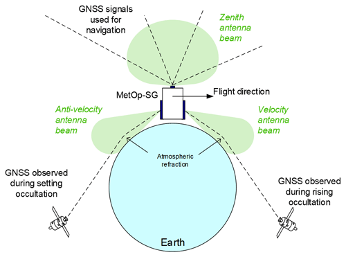
On MetOp-SG satellites, the signals of the transmitting satellites are received via two occultation antennas: one in the flight direction of the satellite (velocity antenna) and one in the opposite direction (anti-velocity antenna) (see Fig. 1). The instrument also receives GNSS signals via a third zenith-pointing antenna with a wide conical coverage. It acquires and tracks GNSS signals and provides the associated observables as part of its measurement data to the ground segment to be used to compute the precise orbit of the spacecraft as well as the offset of the receiver clock. In addition, real-time navigation results are used by the instrument to control its operation. Dual-frequency zenith antenna measurements are also used for measuring electron content of the ionosphere above the orbit altitude.
The RO instrument consists of seven units mounted on three faces of the MetOp-SG satellite as shown in the Fig. 2.
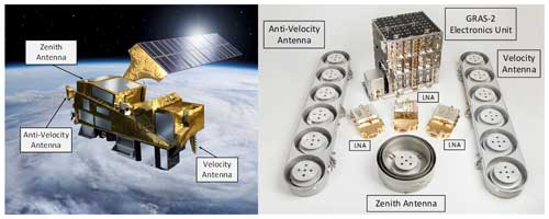
Figure 2MetOp-SG satellite (left, courtesy of the ESA) and the radio occultation instrument (right). The RO instrument includes the following: GRAS-2 electronics unit (GEU), anti-velocity antenna, velocity antenna, zenith antenna, and three low-noise amplifiers (LNAs) for local signal amplification at each antenna.
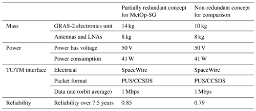
During the design phase, a trade-off analysis was made concerning the addition of redundant modules in the electronics to optimize the overall reliability for the 7.5-year nominal mission duration. This resulted in a design concept with partial redundancy, where the power, interface, and navigation functions have redundant modules at the expense of some additional mass as compared to a non-redundant instrument; see Table 1 below.
Table 1RO instrument accommodation characteristics. Note that TC/TM represents telecommand (TC) or telemetry (TM).
The main instrument performance characteristics are presented in Table 2 below.
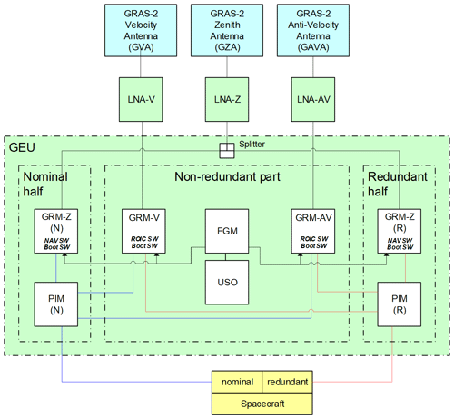
The instrument block diagram is shown in Fig. 3, and the design is described in the following sections. The communication between modules is done using SpaceWire, compliant with ESA standards. The SpaceWire router is housed in the power and interface module (PIM), and it handles communication between modules and with the satellite.
2.1 Antennas
The GRAS-2 zenith antenna (GZA) was developed in the Sentinel 1/2/3 programme. It consists of a patch-excited cup with choke rings for optimum decoupling from the surrounding satellite structure. The antenna receives right-hand circularly polarized signals in two frequency bands, denoted L1 (1575.42 ± 10.23 MHz) and L5 (1176.45 ± 10.23 MHz). Both signals are output through a single coaxial connector (SMA).
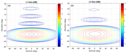
The velocity and anti-velocity antennas (GVA and GAVA) are identical. The design is an array antenna with the same type of element as for GZA, but the size of the cup is reduced to obtain an appropriate inter-element separation distance. A separate beam-forming network in planar technology is placed at the rear side of the antenna. A broadband fixed beam steering is obtained by a linear variation of the length of the lines to the antenna elements. The antenna gain patterns at the respective centre frequency are shown in Fig. 4.
2.2 Low-noise amplifier (LNA)
The LNA is used for filtering and amplifying the weak radiofrequency signal from the antenna. For interference protection, two band-pass filters centred around the L1 and L5 frequencies are placed at the LNA input. The interference rejection of the coaxial cavity filters is more than 50 dB at ±100 MHz from the respective centre frequency. The amplifier stages are designed around discrete gallium arsenide (GaAs) low-noise metal–semiconductor field-effect transistors. The achieved gain is more than 35 dB, and the typical measured noise values of the complete LNA unit are 1.6 dB at L1 and 2.0 dB at L5. The reason for the difference is that a higher filter order is used at L5 for protection against radar interference in the 1215–1350 MHz band (> 35 dB rejection).
2.3 GRAS-2 electronics unit (GEU)
The GEU includes the following modules:
-
GNSS receiver module (GRM). The amplified signal from each LNA is connected to a dedicated GRM. It contains signal amplification, down-conversion, filtering, analogue-to-digital conversion, digital signal processing, and a processor for the instrument control and processing functions needed in the respective GRM. The digital functions are contained in the ESA-developed AGGA-4 device, providing 36 signal channels. Signal tracking is performed by software-controlled algorithms. The GRM packets the measurement data for further distribution over a SpaceWire serial link to a router in the power and interface module (PIM).
-
Frequency generator module (FGM). The purpose of the FGM is to provide local oscillator (LO) signals with low phase noise for the down-conversion of the GNSS signals within the GRMs. The LO signals are phase-locked to an input reference signal at 10 MHz from the ultra-stable oscillator (USO). The reference signal is also amplified and output to the backplane for distribution to all GRMs within the GEU.
-
Ultra-stable oscillator (USO). The USO provides the 10 MHz reference signal to the FGM. The USO is mounted on an extended GEU baseplate next to the other modules. It includes a mu-metal housing for protection against magnetic field variations, which would otherwise affect the frequency of the oven-controlled crystal oscillator. The short-term stability of the USO is better than for gate times in the range of 1 to 100 s. This frequency stability enables very accurate measurements of the Doppler shift introduced by the atmospheric refraction of the radio occultation signals.
-
Power and interface module (PIM). The power and interface module (PIM) receives primary power from the spacecraft, converts it to secondary voltages and distributes these to the different modules within the GEU as well as to the externally located LNA units. The PIM also provides the communication interface for the spacecraft through SpaceWire links from the GRM boards connected to a SpaceWire router hosted in the PIM.
The L5 GNSS band is shared with aviation navigation systems known as distance measuring equipment or tactical air navigation (DME/TACAN). If not accounted for, the transmitted signals from these systems can cause significant degradation of the RO measurements. Hence, the GRMs used for the velocity and anti-velocity receiver chains include frequency-domain adaptive filtering (FDAF) processing for interference suppression. The FDAF processing is performed in a dedicated integrated circuit named Frodo before the signal is input to the AGGA-4 device.
The Frodo device provides a configurable adaptive notching of narrow frequency bands inside the receive signal bandwidth with an updating interval of 8 µs. The interference mitigation capability has been tested for a worst case DME/TACAN scenario with 400 simultaneous interference sources consisting of pulsed transmitters, each with a bandwidth of 125 kHz, spread over a 30 MHz band with 1 MHz spacing. This corresponds to an interference-to-signal ratio () of about 60 dB. The performance is characterized by comparing the signal-to-noise ratio (SNR) of the useful signal for the cases with/without interference and with/without FDAF processing. The test results show that the worst SNR loss due to interference is reduced from 17 to 3 dB when the FDAF processing function is activated. Frodo also provides monitoring through several telemetry parameters including “total RF input power”, “input power spectrum”, and “fraction of spectrum being jammed”. The characteristics of the interference mitigation function are summarized in Table 3.
An instrument data simulator (IDS) has been developed to simulate realistic instrument data. An important part of the IDS for the GRAS-2 instrument is the wave optics propagator (WOP), developed in a collaboration between Chalmers University of Technology and Beyond Gravity (Rasch, 2014). This WOP was also used to generate the atmospheric modulation for the signals used for instrument testing. The IDS generates realistic measurement data and has been used extensively to fine-tune the tracking algorithms during the development of the instrument. To describe the overall tracking scheme, it is best to use the concept of straight line tangent altitude (SLTA). It is the height above ground for a straight line drawn between GNSS and LEO instruments at the point where the line is perpendicular to a radius drawn from the centre of the curvature of the Earth. Above the troposphere, the measure is more or less the same as the tangent altitude of the signal (i.e. the point where the signal makes its closest approach to the Earth surface), but deeper down in the atmosphere the measures start to diverge. The overall scheme is as follows: above 80 km closed-loop tracking of the “Pilot” components of L1 and L5 is performed, and below 80 km the “Data” component is tracked as well. The pilot and data signals are combined during postprocessing to yield a higher signal-to-noise ratio than the individual signals. The closed-loop tracking uses loops to track both the carrier and code of the signals. When the signal goes into the troposphere, the dynamics of the signals can become hard to follow. For this reason, an open-loop tracking algorithm has been developed (Carlström et al., 2012), which ensures that all signal information throughout the atmosphere is made available for ground processing without gaps. Open-loop tracking uses a range model to steer the carrier frequency of the replica signal. The code is tracked using a loop, but before code lock is achieved and during gaps where code lock is lost, the range model is also used here. For setting occultations, the open-loop tracking starts at 20 km SLTA and ends at −300 km SLTA. It uses five correlators. For rising occultations, open-loop tracking starts at −300 km SLTA with 10 correlators. At −38 km SLTA, it switches to five correlators. The large number of correlators allows the signal to be reconstructed in postprocessing even for the segments where there is no code lock. For an ideal atmosphere, there would not be any signal deeper than −100 km, but due to the presence of ducts and the super-refractive phenomena, it is expected that interesting features may appear even as far down as −300 km SLTA (Sokolovskiy et al., 2014). All the heights mentioned above are configurable. Although extensive tuning has been performed with simulations, it is likely that these heights will be changed after the satellites are launched. When producing the bending angle curve, one may freely choose to use purely open- or closed-loop tracking data.
The sampling rate of the instrument shown in Table 2 is higher than for other RO instruments (using typically 50–100 Hz). Higher sampling rates are mainly thought to become important in the troposphere, where moisture can cause the received signal frequency to change very rapidly. Higher sampling rates may contribute to improve the bending angle retrieval in the troposphere. The particular values for sampling rates are chosen so that they align with the navigation data bits of the GNSS signals. The E1b signal has a symbol rate of 250 Hz.
A comparison between the performance of GRAS and GRAS-2 is seen in Table 4.
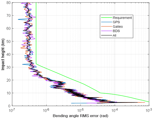
A ground processor prototype (GPP) has been developed to evaluate and optimize the end-to-end performance of the instrument. The most important requirement for the instrument is to provide neutral bending angle data with a root-mean-square error below a specified level (see Sect. 6 below). In order to evaluate this error, the GPP must be able to process simulated and measured instrument raw data to bending angle data. Such an evaluation using measured data processed by the GPP is seen in Fig. 7. As explained in Sect. 4, both open- and closed-loop tracking of the pilot and data signals are performed by the instrument. The quality of the final bending angle depends on how these signals are processed in the GPP. Special algorithms are needed, especially for the open-loop data in the rising occultations. In Fig. 5, the amplitude of nine correlators (a 10th correlator is spaced a bit away from the others and used to track the noise level) for a rising GPS occultation is shown as obtained from the IDS.
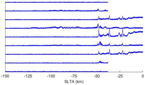
Figure 5Raw multiple correlator amplitudes (linear units) for a rising GPS L1C occultation simulated in the IDS. Correlator numbering is 1 through 9 from bottom to top.
When code lock is achieved, the code loop adjusts the delay for the signal replica so that the centre correlator (fifth from bottom) is aligned with the auto-correlation peak of the signal and hence receives the maximum energy. Before code lock is achieved, it is impossible to know beforehand where this peak will be due to an unpredictable ionospheric delay to the signal. In the case in Fig. 5, before code lock, the main signal energy is recorded by correlator 6. At the point where code lock is achieved, around −50 km SLTA in Fig. 5, the loop adjusts itself rather quickly. This adjustment can be observed by the recorded time stamps and code phase in the data, which means that during postprocessing we can estimate this ionospheric offset. Using a weighted sum over correlators, we can therefore calculate what the amplitude would have been for a fictitious correlator that is aligned with the peak all the way through the occultation. Such a peak correlator algorithm has been specially designed for this instrument. The resulting amplitude after this algorithm has been applied is seen in Fig. 6. Note also in the figure that the number of correlators drops from nine to five at −38 km SLTA where they are no longer needed. The nine correlators allow the code loop to find the peak and start tracking even for quite large ionospheric delays of ∼ 100 m. The peak correlator algorithm allows us to find signal features for very deep occultations, which occur due to rather dynamic tropospheric conditions. To process the signal to bending angle, various algorithms can be employed. In the stratosphere and above, the so-called geometrical optics (Fjeldbo et al., 1971) method is generally used, due to its ease of implementation and speed of execution. To resolve the multipath phenomena (Sokolovskiy, 2001) that occur in the troposphere, one needs to use more sophisticated methods such as the canonical transform (Gorbunov, 2002) and full-spectrum inversion (Jensen et al., 2003). In the GPP, we use the phase matching (PM) method (Jensen et al., 2004). The method is based on stationary phase integrals and relatively straightforward to use. The downside of the method is the rather heavy computational effort needed. Careful optimization has been performed for the GPP so that it can operate in real time (i.e. process an orbit worth of occultations in the time frame of one orbit). Before the bending angle is computed, there are several more steps done by the GPP. The open- and closed-loop data are combined, where the open-loop data are used in the low atmosphere and closed-loop data are used in the high atmosphere. In the transition region where both tracking methods are used, a weighted average is calculated. The final step to calculate the neutral bending angle is to remove the ionospheric bending by combining the L1 and L5 data (Vorob'ev and Krasil'nikova, 1994). The GPP is designed to be used for instrument development, at instrument testing, at satellite-level testing, and for the satellite-in-orbit verification phase after the satellite has been launched.
The low-noise performance of the instrument provides a measured root-mean-square (rms) accuracy of the post-processed bending angle measurements of 0.3–0.4 µrad (typical values) in the upper atmosphere (see Fig. 7), which is better than the EUMETSAT requirement of 0.5 µrad. This is a measured result which is obtained by a test set-up which includes a signal generator capable of simulating the three GNSS constellations (GPS, Galileo, BeiDou) and the modulation from a representative set of atmospheric profiles. The modulation profiles used by the signal generator were generated using realistic atmospheric refractivity profiles and the WOP (see Sect. 4). The raw instrument output is provided to the GPP which produces the neutral bending angle profiles. The result below shows that we expect no significant difference in performance between the three GNSS constellations.
The first RO instrument, the proto-flight model (PFM), was successfully delivered to Airbus Defence and Space in 2020. Figure 8 shows the PFM instrument integrated on the Sat-A PFM in Toulouse. To enable accurate and repeatable testing at the satellite level, antenna test caps are mounted over the antennas when the instrument is integrated into the satellite. A dedicated test equipment then provides the stimuli signals to each antenna such that the function and performance of the instrument can be tested in several stages of the satellite test campaign, also including thermal vacuum conditions.
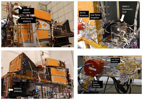
Figure 8Proto-flight model satellite and RO units with test caps to allow for testing at the satellite level. Source: Airbus Defence and Space SAS/GmbH. Notes: MetOp-SG is a collaborative programme between ESA and EUMETSAT. Airbus Defence and Space is the prime contractor, under ESA, for the two satellite series contracts. The photos show the satellite in the assembly phase and not in its final configuration.
The RO instrument on MetOp-SG satellites is designed to provide 1900–2100 occultation measurements per day, thanks to simultaneous tracking of Galileo, GPS, and BeiDou satellites. The instrument also has the capacity to support a fourth constellation in a possible future upgrade. The mitigation of radiofrequency interference from other transmitters in the GNSS bands has been emphasized during the development. A dedicated digital processing device has been developed for this purpose. All performance-critical parameters, including antenna gain, amplifier noise value, and oscillator stability, are superior to those of current-generation instruments. Hence, the measured root-mean-square (rms) accuracy of post-processed bending angle measurements in the upper atmosphere is typically in the range 0.3–0.4 µrad. The GRAS-2 instrument is an important contributor to numerical weather predictions, but it is also highly capable of ionospheric monitoring of electron density and scintillations, as well as for research of phenomena related to deep occultations such as ducting and super-refraction. Novel ground processing algorithms have been developed to utilize the data recorded by multiple correlators, providing optimum performance for deep occultations. All six instruments have now been delivered to Airbus, and the first MetOp-SG satellite is foreseen to be launched in 2025.
The code used to produce the results of this study is available from the corresponding author upon request.
The data underlying the results of this study are available from the corresponding author upon request.
The work and results described in this paper have involved many people, but the authors have played key roles. The manuscript itself was prepared almost completely by AC and JR with support and advice from TL and JC. The sections regarding instrument details and performance were mainly prepared by AC, and the parts on the simulations and ground processing were mostly prepared by JR.
The contact author has declared that none of the authors has any competing interests.
Publisher's note: Copernicus Publications remains neutral with regard to jurisdictional claims made in the text, published maps, institutional affiliations, or any other geographical representation in this paper. While Copernicus Publications makes every effort to include appropriate place names, the final responsibility lies with the authors.
This article is part of the special issue “Observing atmosphere and climate with occultation techniques – results from the OPAC-IROWG 2022 workshop”. It is a result of the International Workshop on Occultations for Probing Atmosphere and Climate, Leibnitz, Austria, 8–14 September 2022.
The authors wish to express their thanks and appreciation for the encouragement and kind support from ESA, EUMETSAT, and Airbus.
MetOp-SG is a collaborative programme between ESA and EUMETSAT. Airbus Defence and Space is the prime contractor, under ESA. Beyond Gravity is the subcontractor for Airbus.
This paper was edited by Andrea K. Steiner and reviewed by two anonymous referees.
Aparicio, J. M. and Deblonde, G.: Impact of the assimilation of CHAMP refractivity profiles in environment Canada global forecasts, Mon. Weather Rev., 136, 257–275, 2008.
Bonnedal, M., Christensen, J., Carlström, A., and Berg, A.: Metop-GRAS In-Orbit Instrument Performance, GPS Solutions, 14, 109–120, https://doi.org/10.1007/s10291-009-0142-3, 2010.
Carlström, A., Bonnedal, M., Lindgren, T., and Christensen, J.: Improved GNSS radio occultation with the next generation GRAS instrument, in: 2012 6th ESA Workshop on Satellite Navigation Technologies (Navitec 2012) & European Workshop on GNSS Signals and Signal Processing, Noordwijk, Netherlands, 5–7 December 2012, IEEE, https://doi.org/10.1109/NAVITEC.2012.6423063, 2012.
Cucurull, L., Derber, J. C., Treadon, R., and Purser, R. J.: Assimilation of Global Positioning System radio occultation observations into NCEP's global data assimilation system, Mon. Weather Rev., 135, 3174–3193, 2007.
Eshleman, V. R.: The radio occultation method for the study of planetary atmospheres, Planet. Space Sci., 21, 1521–1531, 1973.
Fjeldbo, G. and Kliore, A. J.: The Neutral Atmosphere of Venus as Studied with the Mariner V Radio Occultation Experiments, Astron. J., 76, 123–140, 1971.
Gorbunov, M. E.: Canonical transform method for processing radio occultation data in lower troposphere, Radio Sci., 37, 1076, https://doi.org/10.1029/2000RS002592, 2002.
Hajj, G. A. and Romans, L. J.: Ionospheric electron density profiles obtained with the Global Positioning System: Results from the GPS/MET experiment, Radio Sci., 33, 175–190, 1998.
Healy, S. B. and Thépaut, J.-N.: Assimilation experiments with CHAMP GPS radio occultation measurements, Q. J. Roy. Meteor. Soc., 132, 605–623, 2006.
Hocke, K., Igarashi, K., and Pavelyev, A.: Irregularities of the topside ionosphere observed by GPS/MET radio occultation, Radio Sci., 37, 1101, https://doi.org/10.1029/2001RS002599, 2002.
Jensen, A. S., Lohmann, M. S., Benzon, H.-H., and Nielsen, A. S.: Full Spectrum Inversion of radio occultation signals, Radio Sci., 38, 1040, https://doi.org/10.1029/2002RS002763, 2003.
Jensen, A. S., Lohmann, M. S., Nielsen, A. S., and Benzon, H.-H.: Geometrical optics phase matching of radio occultation signals, Radio Sci., 39, RS3009, https://doi.org/10.1029/2003RS002899, 2004.
Kursinski, E. R., Hajj, G. A., Leroy, S. S., and Herman, B.: The GPS Radio Occultation Technique, Terr. Atmos. Ocean. Sci., 11, 53–114, 2000.
Rasch, J.: Theory and Implementation of an End-to-End Radio Occultation Simulator, Technical Report, Earth and Space Sciences, no. 10, Chalmers University of Technology, https://research.chalmers.se/en/publication/203365 (last access: 21 October 2024), 2014.
Rocken, C., Anthes, R., Exner, M., Hunt, D., Sokolovskiy, S., Ware, R., Gorbunov, M., Schreiner, W., Feng, D., Herman, B., Kuo, Y.-H., and Zou, X.: Analysis and validation of GPS/MET data in the neutral atmosphere, J. Geophys. Res., 102, 29849–29866, 1997.
Schreiner, W. S., Sokolovskiy, S. V., Rocken, C., and Hunt, D.: Analysis and validation of GPS/MET radio occultation data in the ionosphere, Radio Sci., 34, 949—966, 1999.
Sokolovskiy, S.: Modeling and inverting radio occultation signals in the moist troposphere, Radio Sci., 36, 441–458, 2001.
Sokolovskiy, S., Schreiner, W., Rocken, C., and Hunt, D.: Detection of high-altitude ionospheric irregularities with GPS/MET, Geophys. Res. Lett., 29, 1033, https://doi.org/10.1029/2001GL013398, 2002.
Sokolovskiy, S., Schreiner, W., Zeng, Z., Hunt, D., Lin, Y.-C., and Kuo, Y.-H.: Observation, analysis, and modelling of deep radio occultation signals: Effects of tropospheric ducts and interfering signals, Radio Sci., 49, 954–970, https://doi.org/10.1002/2014RS005436, 2014.
Vorob'ev, V. V. and Krasil'nikova, G. K.: Estimation of the accuracy of the atmospheric refractive index recovery from Doppler shift measurements at frequencies used in the NAVSTAR system, USSR Phys. Atmos. Ocean, 29, 602–609, 1994.
Yunck, T. P., Liu, C.-H., and Ware, R.: A History of GPS Sounding, Terr. Atmos. Ocean. Sci., 11, 1–20, 2000.
- Abstract
- Introduction
- Instrument design
- Interference mitigation
- Tracking scheme and simulated instrument performance optimization
- Ground processor prototype
- RO instrument performance
- Satellite-level integration and test
- Conclusion
- Code availability
- Data availability
- Author contributions
- Competing interests
- Disclaimer
- Special issue statement
- Acknowledgements
- Financial support
- Review statement
- References


