the Creative Commons Attribution 4.0 License.
the Creative Commons Attribution 4.0 License.
An LES-based airborne Doppler lidar simulator and its application to wind profiling in inhomogeneous flow conditions
Philipp Gasch
Andreas Wieser
Julie K. Lundquist
Norbert Kalthoff
Wind profiling by Doppler lidar is common practice and highly useful in a wide range of applications. Airborne Doppler lidar can provide additional insights relative to ground-based systems by allowing for spatially distributed and targeted measurements. Providing a link between theory and measurement, a first large eddy simulation (LES)-based airborne Doppler lidar simulator (ADLS) has been developed. Simulated measurements are conducted based on LES wind fields, considering the coordinate and geometric transformations applicable to real-world measurements. The ADLS provides added value as the input truth used to create the measurements is known exactly, which is nearly impossible in real-world situations. Thus, valuable insight can be gained into measurement system characteristics as well as retrieval strategies.
As an example application, airborne Doppler lidar wind profiling is investigated using the ADLS. For commonly used airborne velocity azimuth display (AVAD) techniques, flow homogeneity is assumed throughout the retrieval volume, a condition which is violated in turbulent boundary layer flow. Assuming an ideal measurement system, the ADLS allows to isolate and evaluate the error in wind profiling which occurs due to the violation of the flow homogeneity assumption. Overall, the ADLS demonstrates that wind profiling is possible in turbulent wind field conditions with reasonable errors (root mean squared error of 0.36 m s−1 for wind speed when using a commonly used system setup and retrieval strategy for the conditions investigated). Nevertheless, flow inhomogeneity, e.g., due to boundary layer turbulence, can cause an important contribution to wind profiling error and is non-negligible. Results suggest that airborne Doppler lidar wind profiling at low wind speeds () can be biased, if conducted in regions of inhomogeneous flow conditions.
- Article
(11286 KB) - Full-text XML
- BibTeX
- EndNote
Doppler lidar has experienced rapidly growing importance and usage in remote sensing of atmospheric winds over the past decades (Weitkamp et al., 2005). Sectors with widespread usage include boundary layer meteorology, wind energy and airport management. Compared to ground-based Doppler lidar systems, airborne systems can provide advantages and are seen as a promising tool for future research (Baker et al., 1995, 2014; Davis et al., 2018). Airborne Doppler lidar extends the spatial coverage of flow phenomena, enabling stream-wise and span-wise investigation of flow phenomena (Kiemle et al., 2011; De Wekker et al., 2012; Chouza et al., 2016b) as well as targeted observations with rapid deployment (Weissmann et al., 2005; Zhang et al., 2018). Further, airborne Doppler lidar can serve as a testbed and validation tool for upcoming and existing space-based Doppler lidar systems (Paffrath et al., 2009; Lux et al., 2018; ESA, 2018; Baidar et al., 2018; Tucker et al., 2018).
Due to their benefits, various airborne Doppler lidar systems have been developed in the past. Most of the systems are based on long-range aircraft flying in the upper troposphere at high speeds (O(250 m s−1)); thereby, they are destined for sensing the free troposphere due to the coarser spatial resolution (O(5 km) for wind profiling) (Weissmann et al., 2005; Kavaya et al., 2014; Guimond et al., 2014; Tian et al., 2015; Baidar et al., 2018). Some deployments of airborne Doppler lidar have been reported based on medium-range aircraft flying in the lower troposphere and at slower speeds (O(50 m s−1)). These systems yield higher spatial resolution (O(1 km) for wind profiling) and can enable boundary layer studies (De Wekker et al., 2012; Godwin et al., 2012; Koch et al., 2014).
Most currently used airborne wind profiling approaches use the airborne velocity azimuth display technique (AVAD) or closely related retrieval strategies to estimate wind profiles. These approaches assume homogeneous flow conditions throughout the retrieval volume (e.g., no deviations from the mean flow condition). Especially in turbulent environments such as the atmospheric boundary layer, this homogeneity assumption is rarely fulfilled, and wind profiling at high spatial resolution remains challenging (Leon and Vali, 1998; Guimond et al., 2014; Tian et al., 2015). The problem is further intensified by the fact that many airborne profiling systems use high scan elevation angles (closer to nadir). Reasons for doing so include constraint of the measurement footprint, hardware and range limitations or signal attenuation. As a result, the measured radial velocity is strongly influenced by the vertical wind variation along the scan circle. Thereby, violations of the homogeneous flow assumption can lead to non-negligible errors in the retrieved mean wind vector (Tian et al., 2015; Bucci et al., 2018).
A common method to assess the reliability of retrieved Doppler lidar wind profiles is by comparison to wind profiles from other measurement systems. For airborne systems, additional problems exist for in situ comparisons: instrumented towers are of limited use due to their small vertical extent and fixed location (as well as lidar measurement problems due to chirp close to the ground detailed by Godwin et al., 2012), simultaneous aircraft measurements are challenging and expensive to execute (and still suffer from co-location problems), and systems with similar remote sensing characteristics also suffer from co-location problems and results can show large differences (De Wekker et al., 2012; Tian et al., 2015; Bucci et al., 2018). Therefore, the most prominent approach is the comparison of retrieved wind profiles to radiosondes and/or dropsondes, which can provide verification if conducted for a sufficiently large dataset (Weissmann et al., 2005; Chouza et al., 2016a; Bucci et al., 2018). Nevertheless, both systems still exhibit very different sampling characteristics and volumes. This difference often making a direct comparison of the results challenging, as it is difficult to determine if the observed deviations occur due to the differing sampling volumes, violation of the homogeneity assumption or actual instrument error.
Due to these challenges, idealized simulations of Doppler measurement systems can provide detailed insight into the capabilities and limitations of these systems. Early studies determined the representativeness of Doppler lidar measurements based on a statistical description of turbulence and for idealized system setups. Many of the first studies emphasized the effects of measurement geometry and turbulence on system characteristics and performance (Waldteufel and Corbin, 1978; Boccippio, 1995; Banakh et al., 1995; Baker et al., 1995; Frehlich, 2001; Banakh and Werner, 2005). As a result, the reliability of measured radial velocities under different turbulent intensity conditions and its impact on retrieval quality are well described.
With increasing computational capabilities, a numerical approach based on simulated atmospheric wind fields became feasible. For ground-based systems, a number of investigations detailing the error characteristics associated with wind profiling exist based on large eddy simulation (LES) wind fields (Muschinski et al., 1999; Scipión et al., 2009; Scipion, 2011; Stawiarski et al., 2013; Wainwright et al., 2014; Lundquist et al., 2015; Klaas et al., 2015).
For airborne (or satellite-based) systems, the moving platform alters the measurement process and viewing geometry, thereby introducing new problems. These challenges have been investigated with statistical models (Baker et al., 1995; Gamache et al., 1995; Frehlich, 2001) or real measurement data (Leon and Vali, 1998; Weissmann et al., 2005; Tian et al., 2015; Chouza et al., 2016a). For airborne systems, Lorsolo et al. (2013) and Guimond et al. (2014) show the importance of model-based simulator studies, while relying on coarser resolution model output and focused on errors introduced due to the measurement system inaccuracies. So far, to our knowledge, a simulation of an airborne wind profiling system with complex scanning geometries and high-resolution atmospheric wind fields (O(100 m)) is missing.
Extending previous studies, this work investigates the impact of wind field inhomogeneities on airborne wind profiling at highest resolution (O(1 km)). Towards this goal, an LES-based airborne Doppler lidar simulator (ADLS) is presented. Using the ADLS, the measurement and retrieval process can be replicated in great detail, however, with the advantage of knowing the atmospheric input data in the sampling volume exactly. In an example application of the ADLS, this study investigates airborne wind profiling at high resolution (evaluation of single scans, O(1 km) for wind profiling) in a turbulent, inhomogeneous wind field. The error observed in the ADLS between input and retrieved wind profile is directly traceable to the violation of the wind field homogeneity assumed in AVAD, e.g., due to boundary layer turbulence. This direct approach is not possible in other measurement system comparisons or simulations so far.
Consequently, the question addressed is whether the violation of the homogeneity assumption, due to turbulent boundary layer flow, is a relevant driver of error in airborne Doppler wind profiling at high spatial and temporal resolution.
The structure of the study is as follows. In the first section, the ADLS is introduced. This section contains a description of the underlying wind fields, the system simulation characteristics, as well as an outline of the measurement procedure. Further, a simulated nadir transect is analyzed as an illustrative example. In the second section, the error associated with airborne Doppler wind profiling in inhomogeneous flow conditions is investigated using the ADLS. To this end, the wind profiling retrieval and associated error metrics are explained. Then, the sampling procedure and independence of the sampled wind profiles are discussed. After the evaluation of wind profiling error in inhomogeneous flow, the section concludes with an investigation of commonly used quality filtering criteria. At last, the conclusions are given.
The description of the ADLS consists of four sections outlining and mimicking the ADLS structure and operation. First, the underlying wind field options are specified; then, the simulation of the airborne Doppler lidar system components is discussed and the measurement procedure is explained. Last, the nadir or wind profile retrieval can be performed on the simulated measurement data.
2.1 Atmosphere – wind field
In order to be as close as possible to a realistic measurement environment, this study utilizes time-varying LES generated wind fields. The LES fields are simulated using the parallelized LES model (PALM) and provided by the University of Hanover (Raasch and Schröter, 2001).
When using LES, a trade-off between the resolution of the simulation and the domain extent has to be realized, as computational power is limited. On the one hand, the resolution has to be sufficient to ensure a realistic simulation of turbulence and associated Doppler lidar wind measurements. Doppler lidar measurements are assumed to be represented realistically when the lidar range gate length Δp is much larger than the grid spacing Δx of the LES simulation (Stawiarski et al., 2013). On the other hand, the domain has to be large enough to ensure a sufficient number of independently sampled wind profiles for statistical analysis, given the investigated turbulence characteristics, system setup, retrieval strategy and sampling procedure.
The LES used in this study employs a grid spacing of Δx=10 m (corresponding to a resolution finer than O(100 m)) and a domain size of . The grid spacing fulfills the condition Δp≫Δx at the assumed range gate length Δp=72 m (Sect. 2.2.3). Further, the domain size is sufficiently large to sample a sufficient number of independent wind profiles for statistical analysis, given the turbulence characteristics present, an adequate system setup, retrieval strategy and sampling procedure, as is shown in Sect. 3.2. The ADLS can be easily adopted for use with other LES wind fields (e.g., a larger or longer simulation domain), should this be necessary for future studies.
The present LES is driven with a geostrophic background wind of uG=0, 5, 10 and 15 m s−1 and a constant kinematic surface heat flux ( for the 0 m s−1 background wind case). Data output started with fully developed turbulence at a temporal resolution of 1 s after a spin-up time of 1 h. The LES wind fields are the same as used by Stawiarski et al. (2013), and so a detailed description is available in Stawiarski (2014, Sect. 5.1) and Stawiarski et al. (2015). The convective situation is classified as unstable stratification with the stability criteria pointing to the development of organized convective structures for . The boundary layer height is approximately 600 m (1200 m for the 0 m s−1 background wind case), with the entrainment zone extending from 600 to 1000 m. Gravity waves are present in the entrainment zone and above. The stream-wise integral length scales for u and v are in the range of 200–500 m, whereas the span-wise integral length scales are much smaller, in the range of 50–200 m (Stawiarski et al., 2015). Due to the in-depth description in Stawiarski et al. (2015), the used LES data are not detailed further here.
2.2 System – airborne Doppler lidar components
In the second section, all main system components consisting of aircraft, scanner and lidar are simulated geometrically. An illustrative overview of the results obtained after system simulation is shown in Fig. 1.
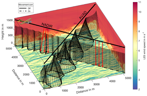
Figure 1Illustration of system and measurement position simulation for two transects through the LES domain. The LES wind speed is color coded. The black lines represent aircraft trajectories. The black curtains show the range gate positions used to conduct the measurement which are calculated from aircraft position, scanner and lidar system simulation. For the first half of each transect, the scanner movement correction is disabled, whereas for the second half, it is enabled. The nadir transect is used to retrieve the vertical wind, whereas the AVAD pattern is used to retrieve the horizontal wind.
2.2.1 Aircraft
The aircraft trajectory is specified by the coordinates of the desired start and end points together with a prescribed aircraft speed relative to air. Curvilinear trajectories are also possible with a specified turn time. Another parameter that can be varied is the aircraft flight altitude.
For a time-varying wind field, as used in this study, the aircraft trajectory and sampling positions inside the LES must be calculated differently than for ground-based measurement systems because the aircraft moves relative to the air mass and not to the ground. As the LES coordinate system coincides with the ground, the sampling distances applied in the LES have to be adjusted for the actual distance covered by the aircraft with respect to the ground, taking into account the movement of the air mass present in the LES. Adjustment of the sampling positions is achieved by taking into account the motion of the aircraft due to the air mass motion during each time step to yield the actual measurement positions in the LES. To this end, the aircraft heading and ground speed are determined iteratively for subsequent time steps, based on the triangle of velocities (Appendix A1). The effect of this procedure can be imagined with an aircraft flying at 65 m s−1 into 65 m s−1 headwind. Relative to the LES coordinate system, this aircraft will stay in the same place. It will thereby sample at the same geographic coordinate in the LES at all times.
The correct simulation of the aircraft motion is important as the sampling of the wind field by the lidar system is altered. In this study, wind speeds reach up to 25 % of the aircraft speed relative to air (IAS). Thereby, the sampling distance between measurements is changed by a factor of up to 0.4 between flying up- or downwind (50 m s−1 vs. 80 m s−1 ground speed), presenting a non-negligible effect. In the ADLS, the aircraft track development is dependent on the wind field, as described above. Additionally, pitch, yaw and roll moments can be added to the aircraft position to simulate the effect of aircraft accelerations on the measurement process. These are superimposed artificially and thereby independent of the track development. This independence is not realistic but deemed sufficient, as aircraft position correction maneuvers should generally not alter the track development (and thereby sampling) significantly, as they will cancel out over short periods of time. Thereby, the effect of aircraft movement due to flight maneuvers can be emulated as well.
2.2.2 Scanner
The scanner movement is simulated with freely selectable scanning geometries and includes an option to correct for the aircraft movement. Subsequent scan positions are calculated in an aircraft-relative coordinate system by specifying the position which should be reached by the scanner, a time needed for the scan movement and a scan mode. Five scan modes are available. The scanner can exhibit stare mode, scan with constant azimuth, constant elevation, along the shortest possible distance on a sphere between two positions or focus on specific positions in the ground reference system (thereby also correcting for aircraft motion). When the aircraft movement correction is enabled, scanner positions are calculated in a ground-relative coordinate system and then transferred back to the respective aircraft-relative coordinate system positions corrected for aircraft movement.
In this study, in order to purely focus on the wind profile retrieval error due to atmospheric flow inhomogeneities, an ideal scanner system is assumed without any beam-pointing inaccuracy (so-called “ideal” system in the following).
2.2.3 Lidar
The simulated lidar is based on the specifications of a Lockheed Martin Coherent Technologies WTX WindTracer system. Lidar systems with similar characteristics are often used in airborne Doppler lidar studies (Weissmann et al., 2005; De Wekker et al., 2012; Chouza et al., 2015; Witschas et al., 2017; Zhang et al., 2018). The lidar beam is emulated in accordance with Stawiarski et al. (2013) and their Gaussian range gate weighting function based on a pulse width of is applied. The same cut-off value, 20 % of the maximum value of the weighting function, is chosen for calculating the effective length of the range gates for the averaging process. Variable range gate lengths and spacings can be specified, in accordance with the standard WTX settings a range gate length of Δp=72 m with a non-overlapping spacing of ΔR0=72 m (the distance between subsequent range gate centers), and a blind zone of 400 m from the lidar is used for this study. The lidar measurement frequency can be varied in the range of 1–10 Hz. The details of how the volume scanned by the laser beam is constructed for averaging during the measurement process are explained in the next section.
Again, in order to purely focus on the wind profile retrieval error due to atmospheric flow inhomogeneities, an ideal laser system is assumed without any random radial velocity fluctuations or other system errors.
2.3 Measurement procedure – motion combination and correction
For the measurement, the aircraft and atmospheric motion vectors need to be combined to give the measured radial Doppler velocities. Additionally, in order to obtain the atmospheric motion vector from the LES, the locations of the lidar range gates need to be calculated. Both operations are conducted based on the state of the system components, meaning the current aircraft orientation and motion, as well as scanner position and lidar setting. Conveniently, this calculation is achieved by defining two separate coordinate systems (Fig. 2), following the theory outlined in Lenschow (1972) and Leon and Vali (1998). The LES wind fields are based in earthbound coordinate system (superscript E) oriented east-north-up (ENU). The aircraft coordinate system (superscript A) is oriented along-right wing-down (ARD). The scanner is emulated and the measurement is performed in the aircraft coordinate system. To transfer between the two systems, coordinate transformations are required; the details are given in Appendix A2.
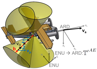
Figure 2Schematic depiction of a possible airborne Doppler lidar system. The sketch is based on an upcoming system for the Dornier 128-6 aircraft of the TU Brunswick (D-IBUF; Corsmeier et al., 2001). The lidar is inside the aircraft pointing outward, with a scanner mounted on the side of the fuselage directing the beam in the atmosphere. The aircraft, scan cone surfaces as well as the coordinate systems and vectors used in Eq. (3) are displayed; for additional information, see Sect. 2.3.
The measured Doppler velocity vD can be calculated through projecting the velocity vectors onto the lidar beam vector. The radial Doppler velocity measured by the lidar has a contribution from the lidar motion vector and the atmospheric motion vector . Both are projected onto the beam direction vector b, which is defined as a unit vector:
The lidar motion can be split into two contributions, the aircraft motion and an aircraft movement moment arm due to aircraft rotation ω with the moment arm r (specifying the distance between the position of the inertial navigation unit in the aircraft and the position of the final mirror turning the lidar beam):
The above assumes that motion towards the lidar is negative, whereas motion away from the lidar is positive. Depending on the lidar beam direction, an airborne Doppler lidar system measures foremost the aircraft speed as it presents a vector with very large magnitude compared to the atmospheric motion vector and the aircraft movement moment arm. The atmospheric motion vector needs to be transformed into the aircraft coordinate system where the measurement is performed using the rotation matrix (see Appendix A2). The same is true for the aircraft motion vector which is originally calculated with respect to the LES coordinate system. Consequently, the measurement is achieved according to the following formula:
Appendix A3 details how the weighted and averaged particle velocity is obtained from the LES considering the range gate position and motion during the measurement process.
Before the application of the retrieval, the contribution of the aircraft motion and aircraft movement moment arm to the measured radial velocity is then removed again:
This calculation isolates the motion-corrected velocity vCOR, which is the atmospheric wind contribution to the measured radial velocity (the projection of the atmospheric wind vector on the beam vector). The ADLS makes it possible to add inaccuracies in any of the components relevant in the measurement or motion correction process. However, please note that throughout this study no system inaccuracies are introduced in the measurement or motion correction process in order to focus on problems in wind profiling due to atmospheric inhomogeneity. In addition, it is assumed that for the real system the optical alignment and beam direction can be reliably quality controlled using a beam calibration procedure based on ground returns. The theory and procedure are outlined in Haimov and Rodi (2013). Consequently, for the ideal ADLS system, the motion-corrected Doppler velocity due to the particle velocity is equal to the particle velocity projection itself. Therefore, compared to a ground-based system, only the measurement geometry is altered due to the moving system. The above-discussed rotations and transformations do not influence the accuracy of the motion correction. As a result, all wind profiling errors discussed in the next sections stem purely from the inhomogeneous atmospheric flow conditions due to boundary layer turbulence. In a homogeneous wind field, the retrieved wind profile is exact.
2.4 Retrieval – nadir as an example application
An illustrative example of the ADLS capability is given by simulated nadir retrievals. In Fig. 3, the simulated vertical wind measurement is compared to the LES input along two transects for an ideal system with a lidar measurement frequency of 10 Hz. The aircraft is flying at an altitude of 1700 m with an IAS of 65 m s−1 and a superimposed 8 s, 5∘ roll oscillation, combined with a 15 s, 3∘ pitch oscillation.
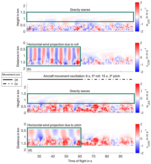
Figure 3ADLS simulated nadir transects for the 10 m s−1 background wind case. The scanner movement correction is disabled for the first half of the transects, whereas it is enabled for the second half. (a) LES vertical wind along a crosswind transect. (b) ADLS motion-corrected velocity measurement along a crosswind transect. (c) LES vertical wind along an upwind transect. (d) ADLS motion-corrected velocity measurement along an upwind transect.
The first transect, a crosswind flight (Fig. 3a, b), reveals the spanwise boundary turbulence structure for the 10 m s−1 background wind case. Along-stream organization of turbulence into rolls occurs, and gravity waves are present above the boundary layer. The ADLS results show that the simulated lidar is able to capture turbulent structures in the boundary layer, although smoothing occurs for the finest scales. Vertically, the resolution of the measurement is defined by the range gate length, whereas horizontally it is defined through the combination of aircraft speed and measurement frequency. Another noticeable effect in the measurement is the movement correction capability of the scanner, which is disabled for the first half of the transect and enabled for the second half. During the first half, the lidar beam is not pointing exactly nadir due to the superimposed, artificial aircraft roll and pitch oscillation. This deviation causes a portion of the horizontal wind to be projected into the measurement. For the crosswind case, this effect is caused by the (rather strong) roll oscillations of the aircraft. Consequently, the measured vertical wind shows some additional superimposed structures compared with the LES for the first half of the transect. This contribution of the mean horizontal wind can be removed, as a second step, if the horizontal wind profile is known (Chouza et al., 2016b). However, variability in the mean horizontal wind profile will still manifest in the vertical wind measurement. The roll and pitch oscillations also result in a distorted curtain location, which is not directly below the aircraft anymore (illustrated in Fig. 1). The winding curtain results in a non-equidistant sampling of turbulence, complicating analysis further. For the second half, the scanner movement compensation is enabled. Consequently, the beam is pointing nadir at all times and no horizontal wind contribution is visible in the measurements.
The second transect, an upwind flight (Fig. 3c, d), reveals the streamwise boundary turbulence structure for the 10 m s−1 background wind case. The flight is conducted in an updraft region of the along-stream organized boundary layer convection; therefore, positive vertical wind speeds dominate. In this case, the superimposed pitch movement contaminates the retrieved vertical wind measurement with a contribution from the horizontal wind if the scanner movement correction is disabled. Thereby, nadir-pointing measurements provide a good opportunity to check the accuracy of the scanner movement compensation and beam direction accuracy using the motion-corrected wind measurement and ground return velocity. Should the movement compensation or pointing accuracy not be satisfactory, it is still possible to calibrate them using the ground return velocity (Haimov and Rodi, 2013). Using this information, the amount of horizontal wind mapped into the vertical wind can be removed in a further post-processing step if the vertical profile of the horizontal wind is known. In order for this method to yield reliable results, an accurate horizontal wind speed estimation is necessary. For this reason, the reliability of wind profiling measurements is the focus of this study.
In this section, the ADLS is used to investigate the error associated with airborne Doppler lidar wind profiling in inhomogeneous flow conditions. Compared to in situ measurements commonly used for wind profiling accuracy evaluation, the ADLS offers more insight, as the representation error due to the different sampling volumes between lidar and in situ measurements does not exist. From real measurements, it is difficult to determine whether the observed wind profile differences are due to the difference in location and/or sampling volume (lidar scanned volume vs. instrumented tower) or due to violated model assumptions (homogeneous wind field) used for retrieval. The ADLS can overcome the co-location problem, as the wind field contributions used to create the measurements are known exactly based on the LES input (Fig. 4).
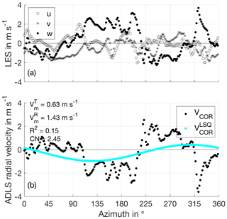
Figure 4Illustration of the wind profile retrieval procedure example for the 0 m s−1 background wind case and 10 Hz lidar measurement frequency for illustrative purpose. (a) Input u, v, w values from LES showing the model truth used to produce the simulated radial velocities. The homogeneity assumption used for AVAD retrieval is clearly violated, as the u, v, w components show deviations throughout the scan. (b) Simulated, motion-corrected radial velocities as well as least-squares (LSQ) fit obtained from singular value decomposition (SVD) inversion used for retrieval. The retrieval results in a positively biased retrieved wind speed, as the vertical wind is erroneously mapped into horizontal wind. Please note that as movement towards the lidar is negative by convention, an updraft in ENU (positive vertical velocity) results in a negative radial velocity, as the lidar is looking down and air is moving towards the lidar.
To this end, in this section, the wind profiling retrieval and associated error metrics are explained. Then, the sampling strategy and independence of the sampled wind profiles are discussed. After the evaluation of wind profiling error in inhomogeneous flow, the section concludes with an investigation of commonly used quality filtering criteria.
3.1 Wind profiling theory and associated error metrics
The theory and problems associated with airborne Doppler wind profiling are very similar between lidar and radar systems. Therefore, no distinction is made between the studies using either of the two instruments in the following, unless necessary due to explicit differences. Similar to ground-based wind profiling, airborne wind profiling is usually conducted by scanning in conical scans along the flight path. Retrieval of the mean wind vector can be achieved through inversion of the beam matrix, yielding a least-squares solution to the problem (Leon and Vali, 1998). De Wekker et al. (2012) and Tian et al. (2015) apply the original velocity azimuth display (VAD) analysis directly, while neglecting the altered beam geometry due to aircraft movement. Other methods at higher computational cost exist as well. Guimond et al. (2014) discuss a variational approach which can improve the traditional solution by adding anelastic mass continuity constraints on the estimated solution. Accumulation of the Doppler spectra can be conducted for Doppler lidar and has been shown to extend the retrieval limits in clear air conditions with little return signal (Weissmann et al., 2005; Witschas et al., 2017).
In this study, a standard inversion-based approach outlined by Leon and Vali (1998) for airborne wind profile retrieval is followed. In this method, multiple radial velocity measurements under different beam-pointing directions are sampled from an atmospheric wind field, e.g., by scanning (see Fig. 1 for an illustration of the scan trajectory). The inverse problem is then solved by calculating the inverse of the beam-pointing matrix (for the associated formulas and details, see Appendix A4). Thereby, a least-squares (LSQ) estimate of the wind vector, which was responsible for the observations, is obtained (see Fig. 4 for an illustration of the LSQ-fit procedure). In this study, a singular value decomposition (SVD) is performed to calculate the inverse. The SVD solution yields benefits compared to the direct solution, as a number of reliability control parameters become available (Boccippio, 1995).
The retrieval error is defined as the difference between the true wind speed , calculated from the input LES wind field as discussed below, and the ADLS retrieved wind speed , obtained from wind profiling (see Fig. 5 for an example on the obtained wind profiles and associated errors):
In this study, the wind speed Vm is calculated from all three components, . For the quantitative analysis, four metrics are employed, consisting of the root mean squared error (RMSE), the relative root mean squared error (REL), the number of available wind profile points (N) and the retrieval bias, defined in Appendix A5.
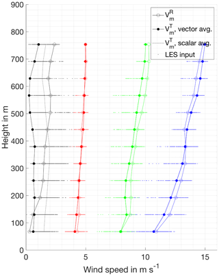
Figure 5Examples of retrieved wind profiles and associated LES input truth for all four background wind cases. Retrieval errors are due to the homogeneity assumption used for retrieval being violated. For the 0 m s−1 background wind case, the effect of scalar vs. vector averaging is detectable in the difference between the individual LES wind speed input values and the vector average value (discussed in Sect. 3.4). The retrieval for the 10 m s−1 background wind case shows that the retrieved value can lie outside the range of input values. Retrieval errors are correlated over multiple altitudes (resembling a bias but being random for different profiles) as turbulence is correlated vertically.
To compare the simulated retrieved wind speed, an LES-based model truth has to be defined. This study follows the approach described in Wainwright et al. (2014) to define the model truth. In this, the model truth is the average over the points in the sampling volume touched by the lidar beam after weighting by the lidar weighting function (Sect. 2.2.3). In this study, the vector average is used as the wind speed averaging method. Vector averaging is more representative of the lidar-measured wind speed than scalar averaging, as the lidar averages the wind field over a large area rather than summing up individual contributions without respect for directional change. The method used makes a difference especially for lower wind speed cases (illustrated in Fig. 5, discussed in depth in Sect. 3.4). The advantage of the direct, equal-volume-based LES–lidar comparison, as noted by Wainwright et al. (2014), is that differences which occur between the simulated measurement and model truth are exclusively traceable to the wind field inhomogeneities. Therefore, optimization of the measurement system setup with respect to the impact of wind field inhomogeneities is possible. When an ideal system is assumed, with no measurement system inaccuracy and no co-location problem, the results are also useful as they present a lower bound to the observable Doppler lidar error. A lower error cannot be observed from real in situ comparisons (assuming equal atmospheric conditions, measurement system setup and retrieval strategy), as the error given in this study specifies the inherent error due to the Doppler lidar viewing geometry and retrieval settings.
The simulation results presented in the following are not directly transferable to real-world wind profiling comparisons. Today, no measurement system is able to trace the exact volume touched by the lidar beam and thereby measure the input truth, as is done in the ADLS. Therefore, a real-world comparison should result in larger error levels than what is presented here, due to additional co-location problems and due to the different wind vector measurement principles (Bradley et al., 2012). It seems worthwhile to extend the analysis in this direction at a later point, as the underlying statistical foundation exists already (Frehlich, 2001). The topic is not addressed here, as it is beyond the scope of this work.
3.2 System setup, retrieval strategy and sampling procedure
The retrieved wind profiles are sampled from the LES domain in temporal and spatial proximity. Independence of the retrieved wind profiles is important to ensure a sufficiently large and independent dataset for robust analysis with reliable values. Therefore, correlation is minimized through an adequate measurement system setup, retrieval strategy and sampling procedure explained in the following. However, it should be noted that any potential correlation in wind profiling error does not affect the reported errors levels systematically (RMSE, REL, bias). Correlation reduces the number of effectively available wind profiles and thereby influences the uncertainty with which the error levels are estimated, but it does not impact the error levels themselves. Nevertheless, in order to achieve a sufficiently large statistical sample size, correlation is minimized through an adequate measurement system setup, retrieval strategy and sampling procedure. To this end, all profiles are sampled from non-overlapping measurement domains in time and space (termed “checkerboard approach” in the following), illustrated in Fig. 6 and explained in the following.
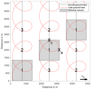
Figure 6Illustration of checkerboard approach used for wind profile retrieval. Shown are the locations of the three transects and associated retrieval volumes for the first time step. Retrieval volumes are shifted to the enumerated positions for subsequent time steps, while flight trajectories are repeated. Additionally shown is the lidar ground track.
The measurement system setup is simulated based on an intended upcoming airborne Doppler lidar system for boundary layer research. The simulator settings are adjusted accordingly, an overview of parameter settings is given in Fig. B1. The aircraft characteristics are based on an unpressurized, medium-range turboprop aircraft, flying above the boundary layer at measurement speed under visual flight rules. Therefore, the aircraft is flying at an IAS of 65 m s−1 and the aircraft altitude is set to 1100 m. Combined with the chosen scan elevation angle, this setting gives equal along- and across-track retrieval volume averaging distances.
The scan pattern used in this study is based on the scan geometry of existing systems (Weissmann et al., 2005; De Wekker et al., 2012; Bucci et al., 2018). It consists of a 20 s full circle scan time (scan speed ) at 60∘ elevation (30∘ off-nadir). The scan trajectory starting point is chosen randomly at each time step in order to ensure sampling of different locations by the lidar beam. Additionally, the scan rotation direction is reversed for subsequent transects through the LES.
The lidar measurement frequency is set to 1 Hz, with pulse width and range gate settings according to Sect. 2.2.3. Changing the measurement frequency to 10 Hz does not alter the results significantly, as the additional measurements are strongly autocorrelated (see Fig. 4). Consequently, the greater number of measurements does not provide new information to the retrieval, nor does it result in a better fulfilled homogeneity assumption.
The wind profile retrieval consists of u, v, w component retrieval using a volume-based profile separation. Retrievals are obtained from along-track averaging over Xa=1300 m and the same across-track averaging distance of Xc=1300 m. The along-track averaging distance is based on the distance covered by the aircraft during one full scan rotation. The across-track averaging distance corresponds to the maximum across-track distance covered by the lidar beam at 60∘ elevation and a flight altitude of 1100 m above ground. The vertical wind profile resolution is chosen as 62 m, yielding one range gate within every vertical layer. Only wind profiles within the boundary layer and entrainment zone are compared as this study focuses on retrieval error under inhomogeneous, turbulent conditions. Therefore, the maximum wind profile altitude is set to 800 m, preventing the impact of larger scale features such as gravity waves with longer de-correlation scales.
Three flight trajectories traverse the LES domain in parallel from south to north at a horizontal distance of 1750 m to each other, in a crosswind flight direction. Each of the three trajectories is repeated 28 times at 1 min temporal spacing, giving a total number of 84 actual transects. To avoid correlation among the analyzed profiles from different transects, all profiles are sampled from non-overlapping measurement domains in time and space, illustrated in Fig. 6.
To this end, only one wind profile is retrieved for each transect. The retrieval volumes for the parallel transects at each time step are arranged in a checkerboard pattern to ensure maximum spatial independence. The distance between spatially neighboring transects and measurements is larger than the integral scale of turbulence in the LES, generating statistical independence.
The checkerboard pattern is shifted by Xa along flight track for subsequent transects, thereby also ensuring temporal independence of the retrieved profiles. After three time steps, the retrieval volume shift procedure is repeated. Thereby, the same location is sampled only every 3 min. The decorrelation of the retrieved profiles is aided by crosswind advection and the pencil-beam nature of the lidar beam. While large-scale structures in the flow, e.g., due to coherent turbulence, may persist over some time and distance, small-scale variation is more rapid. The small-scale variation is expressed by the short integral length scales of the LES flow at 50–500 m, denoting the spatial distance over which turbulence is statistically independent from the previous sample. A random offset within one retrieval volume length is added to all retrieval volume start points within one retrieval volume shift procedure. The random start point prevents a systematic influence of the transect beginning location on measurement quality for the different flight directions.
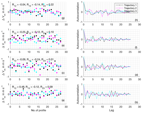
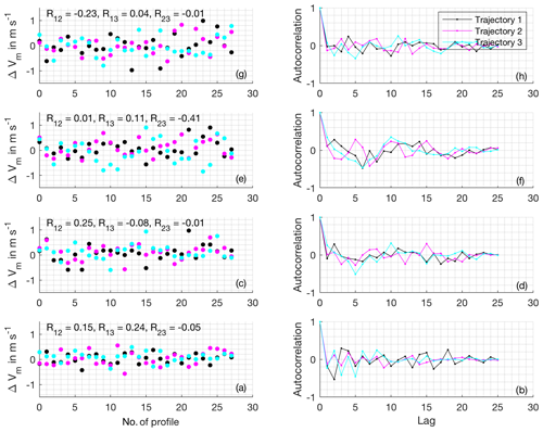
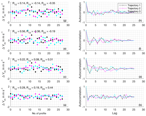
An analysis of the spatiotemporal correlation of the obtained wind profile retrieval errors ΔVm shows that the obtained errors are independent to a high degree for all background wind speed cases, time steps and retrieval altitudes (Figs. B2, B3, B4 and B5). The autocorrelation functions allow for evaluation of both, the spatial as well as the temporal correlation of profiling error, at the same time for the chosen checkerboard approach. On the one hand, the autocorrelation values at lags 1, 2, 4, 5, 7, 8 and so on reveal the spatial correlation of wind profiling error between neighboring retrieval volumes. On the other hand, the autocorrelation values at lags 3, 6, 9 and so on reveal the temporal correlation of retrieval error for the first retrieval volume (as the retrieval volume shift procedure is repeated after a cycle of three volumes, the same volume is sampled again at these lags). Taking into account the small number of points used to calculate the autocorrelation functions, they do not display concerning systematic structure (e.g., repetitive with cycle durations 2 or 4, or similar between trajectory or altitudes). The marginal structure present beyond the noise resulting from the small sample size can be explained by large-scale organization of turbulence on scales similar to the spacing of the retrieval volumes. Examples of weak structures are the alternating correlation coefficients for the first lags of trajectory 1 in the 0 m s−1 background wind case at low altitudes (Fig. B2), as well as the slightly negative correlation for lag 1 in the 15 m s−1 background wind case at low altitudes (Fig. B5). As the associated correlation coefficients remain small (<0.5 in almost all cases), the number of effectively available wind profiles is not affected strongly by these effects.
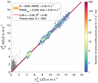
Figure 7Comparison of LES truth and ADLS retrieved wind speed for an ideal measurement system with quality filtering criteria applied. All measurements which pass quality filtering are color coded; gray crosses indicate the ones which do not. The observable deviations from the 1:1 line reveal retrieval errors due to the violation of the homogeneity assumption used in AVAD.
Please note that despite investigating an overall independent error (between spatially and temporal different profiles), the error of vertically adjacent wind profile points is not random for an individual profile (see Fig. 5). The error between neighboring vertical profile layers is not random because turbulent structures are correlated between vertically adjacent layers. This makes an individual wind profile appear smooth, despite overall random error being present. The magnitude of the random error only becomes noticeable when looking at profiles sampled at different locations or times (this disguise is likely one of the reasons why the error due wind field inhomogeneities has received little attention in literature so far). The vertical correlation effect is present in both the ADLS and real measurements with equal magnitude.
3.3 Evaluation of error in wind profiling
The previous section showed that a statistical analysis of error in wind profiling is possible using the given system setup, retrieval strategy and sampling procedure.
The ADLS simulation allows for retrieval of 336 individual wind profiles giving 4032 wind profile points for all altitudes (12 wind profile points per wind profile at the different retrieval altitudes). These consist of 84 wind profiles (1008 wind profile points) for each background wind case, yielding a sufficient statistical basis for evaluation. The 336 wind profiles (4032 wind profile points) are more than what is typically available for comparison in real-world measurements, as co-located validation measurements are very difficult and costly to conduct. For example, 33 wind profiles (740 wind profile points) are compared to dropsonde data in Weissmann et al. (2005), approximately 10 wind profiles to a ground-based wind profiler in De Wekker et al. (2012), a single wind profile to dropsonde data in Kavaya et al. (2014) and approximately 49 wind profiles (2056 wind profile points) to dropsonde data in Bucci et al. (2018), with each of them mentioning the importance of the spatially differing sampling volumes and associated problems.
The wind profiling quality of the standard system setup and retrieval settings in the investigated inhomogeneous flow conditions can be evaluated from Fig. 7. As discussed above, the wind profile retrieval is made assuming an ideal measurement system; thereby all deviations are directly traceable to AVAD assumption violation due to wind field inhomogeneities. For quality filtering purposes, a minimum coefficient of determination of and a maximum condition number CNmax<9 are applied. Similar values have been recommended and used in the past by Boccippio (1995); Päschke et al. (2015); Wang et al. (2015). The effect of quality filtering on retrieval quality is investigated in detail in Sect. 3.4.
A total number of 3006 (of the 4032 retrieved) wind profile points pass quality filtering and the results provide a number of interesting observations. Firstly, the wind speed retrieval is unbiased provided that an appropriate retrieval strategy is used and appropriate quality filtering criteria are applied (discussed in Sect. 3.4). Overall retrieval quality is high, with R2=0.99 and . Yet, even with strict quality filtering applied, deviations above 1 m s−1 can occur. The LES cases with higher wind speeds show higher wind variability and increased absolute wind speed retrieval error. With decreasing wind speed (separately for each of the cases), associated with measurements in the boundary layer under turbulent conditions, deviations increase but remain unbiased. Interestingly, the 1008 retrieved wind profile points for the 0 m s−1 background wind case are completely excluded by the quality filtering criteria (as well as 18 wind profile points from the 5 m s−1 background wind case). They also show much higher wind speed retrieval scatter and can introduce a positive bias if inappropriate quality filtering criteria are applied, although the individual retrieved components themselves are unbiased (Fig. B6). The reasons behind this are discussed in Sect. 3.4, where the effect of quality filtering is thoroughly investigated.
The vertical distribution of wind profile error mirrors that of the responsible boundary layer turbulence (Fig. B7). Errors are largest in the middle of the boundary layer where up- and downdrafts have maximum intensity. Towards the ground, a slight reduction in wind profiling error is observable for all wind speed cases. There, the size of the turbulent elements becomes smaller and consequently the lidar scan averages over more eddies, thereby better fulfilling the homogeneity assumption. This is a theoretical result; in real measurements, other effects such as ground chirp will degrade near-ground retrieval of wind profiles (Godwin et al., 2012). Towards the top of the boundary layer, wind profile error decreases as the homogeneity assumption is better fulfilled. Nevertheless, entrainment and detrainment processes can still cause noticeable retrieval error, especially for higher wind speed cases. In the free, homogeneous atmosphere, wind profile error vanishes (not shown).
The wind direction retrieval (Fig. B8) is of similarly good quality compared to the wind speed retrieval. The wind profile points which pass quality filtering cluster in a small area around 270∘, representing the westerly wind direction. The wind direction retrievals for the 0 m s−1 background wind case scatter throughout the full range as the wind direction is not meaningful without a background wind speed. As before, these values are completely eliminated by quality filtering. The retrieval exhibits slightly degraded quality criteria (lower R2, small y-axis intercept) compared to the wind speed retrieval. However, this behavior is due to the data not being distributed over a wide range, as is the case for wind speed.
3.4 Quality filtering criteria
Assessing the reliability of the parameters retrieved through the inversion process is a common problem in inverse theory, and two metrics are investigated as a part of this study.
The coefficient of determination R2 (Appendix A4, Eq. A22) is often used to detect a violation of the homogeneity assumption (Päschke et al., 2015; Wang et al., 2015). When using this approach, it is assumed that deviations from the homogeneous state show up as deviations of the measurements from the LSQ fit. Wind field inhomogeneities smaller than the scan volume size decrease the R2. Therefore, it is commonly assumed that the R2 captures the degree of violation of the homogeneity assumption. Often-used filtering criteria are R2>0.8 or R2>0.95 for ground-based wind profiling (Wang et al., 2015; Päschke et al., 2015). However, as shown already by Koscielny (1984), a linear change in the vertical wind biases the retrieved horizontal components and a linear change in the horizontal components biases the retrieved vertical component. Both deviations are not detectable as deviations from the LSQ fit.
If the matrix inversion is performed based on a singular value decomposition, additional quality criteria such as the condition number (CN) (Appendix A4, Eq. A20), describing the degree of collinearity among the model geometry, become available and are frequently utilized (Boccippio, 1995; Holleman, 2005; Cheong et al., 2008; Shenghui et al., 2014; Päschke et al., 2015; Wang et al., 2015). The CN provides a measure of the spread of the model space, thereby diagnosing collinearity (Boccippio, 1995; Leon and Vali, 1998; Shenghui et al., 2014; Päschke et al., 2015; Wang et al., 2015). A high CN indicates high collinearity in the model geometry. Consequently, the real system state is not well explored in at least one direction, and as a result the inferred system state is prone to a large error amplification (Boccippio, 1995). The CN is often used as a quality filtering criteria to exclude measurements where the spread of the beam-pointing directions is not sufficient to explore the wind field adequately (Boccippio, 1995; Päschke et al., 2015; Wang et al., 2015). In this section, the performance of the most commonly used quality criteria (R2 and CN) is evaluated, specifically their relation to wind profile quality and their adequacy in detecting violations of the homogeneity assumption and collinearity in the model geometry.
The analysis of the simulator results for the ideal measurement system setup and standard retrieval setting reveals a number of interesting findings (Figs. 8 and B9 for the full range of non-quality-filtered values). Deviations from the geostrophic background wind towards lower wind speeds, associated with stronger turbulence in the boundary layer, generally decrease the value of the R2 but do not influence the CN, as it is expected (Fig. 8c, f). Even at high R2>0.90, significant wind profile errors up to 1 m s−1 do exist. The CN values cluster in a narrow range with values between 3 and 4, as the sampling volume is generally well explored by the lidar for all retrievals due to the checkerboard approach.
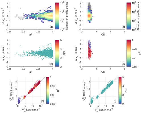
Figure 8Quality filtering criteria for the standard system setup and retrieval strategy. (a) Color-coded histogram of number of occurrences for retrieval error and R2. Gray crosses show values eliminated by quality filtering. (b) Retrieval error and R2; CN is color coded. (c) LES wind speed and ADLS wind speed; R2 is color coded. Profile points which pass quality filtering are displayed as color-coded circles; profile points which are eliminated are shown as color-coded crosses. (d) Same as panel (a) but for CN. (e) Retrieval error and CN; R2 is color coded. (f) Same as panel (c) but for CN.
A noteworthy feature occurs for the 0 m s−1 background wind case. Here, a clear dependence of wind speed error on the R2 value is observable (Fig. B9a, b, c). The estimated wind speeds are only slightly biased for coefficients of determination in the range close to 0. However, with increasing R2, the bias of the retrieved wind speed increases linearly to values in the range 1–2 m s−1. This problem exists despite the fact that the individual estimated components themselves are unbiased (Fig. B6). Coefficients of determination above 0.9 are non-existent for the 0 m s−1 background wind speed; therefore, the biased values can be filtered completely. The observed behavior is caused by the lidar measurement method: at low wind speeds, the measured radial velocity and thereby also the retrieval is strongly influenced by the vertical wind and less by the horizontal wind, especially at elevation angles closer to nadir (see also Fig. 4). For a horizontally sheared vertical wind field, exactly in phase with the measurement geometry at scan elevation angle φ and with magnitude w (a worst-case scenario, leading to no detectable variation in the LSQ fit), the erroneous mapping follows . For high coefficients of determination, the vertical wind variations are more in phase (with an expected horizontal wind contribution from the simplified horizontal wind field model) and thereby mapped more into horizontal wind, causing a stronger positive bias. The values of the horizontal wind speed in the range of 0–3 m s−1 correspond with a mean vertical wind of 0–1.5 m s−1 amplitude being mapped into the horizontal wind at 60∘ elevation. At lower coefficients of determination, the noisy (sub-scan-volume) vertical wind variations overwhelm the smaller horizontal wind speed signal. However, they do not lead to a mean wind speed being estimated as they cancel out due to averaging, thereby causing no bias. If the scalar averaged LES wind speed is used for lidar comparison instead of the vector-averaged LES wind speed discussed here, the described linear trend is equally present but with an intercept offset of along the y axis. However, for elevation angles closer to the horizontal, giving more accurate retrievals, the estimated lidar wind speed tends towards the vector average, making it the correct choice for comparison.
In summary, for low wind speeds, the application of a higher R2 mainly filters for smoother in-phase variations of the vertical wind. Consequently, selecting an inadequate threshold for R2 can cause a bias, an important finding that is not expected and, to our knowledge, undocumented so far. For low wind speed cases, the R2 is not an appropriate quality filtering criteria, unless an appropriately high threshold is chosen which then successfully filters the low wind speed cases.
For the retrievals investigated here, a clear separation between biased retrievals from the 0 m s−1 background wind case and the non-biased retrievals from the 5 m s−1 background wind case is possible, based on R2>0.9 threshold filtering. However, in reality, this separation is not necessarily possible, as intermediate background wind speeds in the range of 0–5 m s−1 might be present. These cases may also result in biased retrievals, as long as the radial velocity contribution of the vertical wind is of comparable magnitude to that of the horizontal wind, giving the possibility for non-negligible erroneous mapping. A possible bias for unknown reasons, varying by day, has been reported by Weissmann et al. (2005) already. They stress the need for further investigation of this phenomena using simulated lidar data. The bias at low wind speeds is also noticeable in studies comparing lidar-measured wind speeds to in situ measurements; however, it is without discussion or explanation so far. Some recent examples of the observed overestimation at low wind speeds are, besides others, visible in Holleman (2005) (ground based; Figs. 4, 5), Chouza et al. (2016a) (airborne; Figs. 2, 3b under turbulent conditions inside the boundary layer) and Pauscher et al. (2016) (ground based; Fig. 5e).
Therefore, based on the above discussion, we recommend the following procedure in wind profile analysis. In doubtful situations, where the approximate magnitude of the measured wind speed is unknown, one should always analyze a long spatial average over multiple scan rotations first (approximately 10 times the expected maximum eddy size). For longer averaging, the mapping of vertical wind does not influence the retrieval significantly, as the structure of the vertical wind is not in phase with the measurement geometry over long distances (except for extended regions of horizontally sheared vertical wind, e.g., in complex terrain). Thereby, the approximate magnitude of the wind speed can be analyzed reliably, although at coarse spatial resolution. If the outcome of this analysis is a wind speed magnitude below 5 m s−1, and a non-negligible vertical wind with similar magnitude is present, a further analysis at higher spatial resolution is not advisable due to the possibility of erroneous mapping. If, on the other hand, the wind speed magnitude is above this threshold, or the vertical wind magnitude is negligible, the spatial resolution of the retrieval can be refined further. In the case of a sheared wind speed profile, e.g., low wind speeds close to the ground and higher wind speeds above, the required averaging distance varies vertically. As along- and across-track averaging distances used in the retrieval are freely selectable parameters, they can also be adjusted vertically in order to allow for an optimal retrieval with the highest resolution. In the future, if advanced and flexible measurement system are available, it also appears possible to adjust the measurement system setup based on the encountered wind field conditions. For this procedure, an analysis of preferable measurement system setups and retrieval strategies which are less influenced by erroneous mapping appears worthwhile to conduct in future studies.
Leaving the low wind speed problem aside, even when using strict quality filtering criteria, considerable wind speed retrieval error can still exist due to inhomogeneities. Or, stated in another way, even relatively small deviations from the homogeneity assumption that do not lead to significant degradation of the quality filtering criteria can cause noticeable retrieval error. For these cases, the possibility of a data-driven uncertainty estimation (e.g., based on the measured radial velocity variance) appears promising to investigate.
Overall, it can be concluded that wind profiling error due to violation of the homogeneity assumption can be of non-negligible magnitude. The errors reported in this study, solely due to flow inhomogeneity, are of comparable magnitude to, or even above, what has been reported as overall wind profiling error in other studies (Weissmann et al., 2005; De Wekker et al., 2012; Bucci et al., 2018). Wind profiling error due to flow inhomogeneity should therefore not be neglected as an important source of error when evaluating the measurement accuracy of airborne Doppler lidar systems.
In this study, an LES-based airborne Doppler lidar simulator is presented to provide a link between Doppler lidar theory and measurements. As an example application of the ADLS, the error associated with wind profiling in turbulent flow conditions is investigated. This error results from a violation of the homogeneity assumption used for wind profile retrieval and can be isolated using the ADLS, as the input truth used to create the measurements is known exactly.
The ADLS utilizes an LES wind field at 10 m grid spacing to simulate the turbulent convective boundary layer with geostrophic background wind speeds of 0, 5, 10 and 15 m s−1. The emulated measurement system consists of an aircraft, scanner and lidar, considering many geometric transformations applicable in real-world measurements. After system emulation, a simulated measurement is conducted based on the LES wind fields. The ADLS does neither include a simulation of the signal return (aerosol scattering) process nor of the lidar instrument physics. These processes have been investigated adequately elsewhere and problems associated with them are expected to be of manageable magnitude in practice. Instead, a direct measurement approach as chosen by other recent studies is further extended here (Stawiarski et al., 2013; Guimond et al., 2014).
As an example application of the ADLS, the accuracy of high-resolution airborne wind profiling under inhomogeneous, turbulent flow conditions inside the boundary layer is investigated. For this application, the ADLS demonstrates its usefulness, as representation problems present in studies comparing lidar to in situ measurements can be avoided. Thereby, we are able to provide a quantitative analysis of airborne Doppler lidar retrieval error due to the violation of the homogeneity assumption used in AVAD.
Results show that the standard system setup and retrieval strategy investigated (based on the characteristics of existing systems) allow for wind profiling with acceptable accuracy in inhomogeneous flow (RMSE for wind speed). Nevertheless, retrieval errors due to the violation of the homogeneity assumption used for retrieval are non-negligible and can present a major contribution to overall wind profiling error. An important new finding of this study is that Doppler lidar wind profiling, at low wind speeds under turbulent conditions, can be unreliable and even biased despite applying quality filtering criteria. For low wind speeds, erroneous mapping and filtering of the vertical wind into horizontal wind can occur, thereby biasing the retrieved wind speed. In order to resolve this issue, an analysis of preferable measurement system setups and retrieval strategies, which are less prone to erroneous mapping, appears worthwhile to investigate in future studies.
Overall, this study highlights the benefit of an LES-based airborne Doppler lidar simulator. The ADLS offers a promising opportunity to investigate the lidar measurement process more closely, not only with respect to wind profiling but, for example, also with respect to estimating turbulent quantities from nadir measurements. Further, the ADLS can also serve as a algorithm testbed for more complex retrieval approaches such as airborne dual Doppler. Regarding AVAD wind profiling, it is necessary to investigate the possibility of an in situ uncertainty estimation of retrieved wind profiles based on the measured data. Here, the ADLS can provide a valuable contribution by allowing for method validation under close-to-realistic conditions, while knowing the input truth, which is nearly impossible in real measurement setups.
A1 Triangle of velocities
Given for this example are the in-air speed (IAS), the aircraft ground track direction (TR), the wind speed (WS) and the wind direction (WD). Directions are to be given in degrees from north and speeds in the same units. Needed are the aircraft heading (HDG) and the ground speed (GS). We can calculate them according to the following formulas:
The calculations can be performed for other combinations of given and needed variables as well.
A2 Coordinate transforms
As outlined in Lenschow (1972) and Leon and Vali (1998), transformations between the LES earthbound (E) coordinate system, oriented ENU and the aircraft (A) coordinate system, oriented along ARD, are achieved by using the standard heading–pitch–roll procedure using the transformation matrix 𝕋. The coordinate transform matrix from the aircraft ARD reference frame to ground ENU reference frame is 𝕋AE (A to E). Here, the transformation is conducted for the beam direction vector as an example. It can be transferred between the two systems with
and
The transformation matrix can be split into separate rotations around the individual aircraft axes:
Hereby, ℍ denotes a heading rotation at angle ψ (yaw around the z axis), ℙ a pitch rotation at angle θ (pitch around the y axis) and ℝ a roll rotation at angle ϕ (roll around the x axis). Individually, they are given as
Combined, this results in
A3 Lidar beam position, lidar beam motion and averaging of the LES wind field
In order to determine the LES wind velocity () which is projected onto the beam, the range gate position has to be calculated. As the position is needed for the LES, it must be calculated in the ground reference system. Therefore, after transferring the beam direction into the ground reference system (Appendix A2), the range gate center positions are calculated by adding the range gate center distances R0 (spaced apart) in beam orientation to the aircraft position:
This calculation is repeated for the range gate beginning and end positions by subtracting or adding half the range gate length to R0:
Thereby, the range gate position at the average measurement time is fully characterized; however, the range gate motion due to aircraft motion and scanner movement still needs to be accounted for.
The motion of the range gate during one measurement is accounted for by defining a volume between the range gate position at the beginning and the end of the measurement process. The two positions are calculated using a range gate motion vector. The range gate motion vector is constructed by using the difference of the range gate center position compared to the end range gate position of the previous measurement (this assumption is valid as only continuous aircraft and scanner movements are investigated). Using these positions, difference vectors are constructed for the range gate beginning, center and end positions. The first and last range gate positions during one measurement are then obtained by subtracting and adding the range gate motion vector from the range gate center position.
The real lidar beam only has a beam diameter of approximately 10 cm. This diameter is not enough to ensure an adequate sampling of LES data (grid spacing is Δx=10 m). Therefore, the beam volume is artificially enlarged in the direction orthogonal to the motion. The factor is set in relation to the grid spacing; a minimum distance of half the grid point distance is employed to ensure points inside the volume:
After all points that fall inside the volume covered by the lidar beam are determined, they are weighted according to the range gate weighting function (Sect. 2.2) based on their orthogonal distance from the beam center. Last, a linear averaging is applied to obtain the average velocity of all points in the volume. This averaged velocity is then projected onto the beam direction according to Eq. (3).
A4 Wind profile retrieval theory
In the AVAD method, multiple radial velocity measurements under different beam-pointing directions bn are sampled from an atmospheric wind field with mean wind vector vp:
The beam directions from multiple measurements make up the beam-pointing matrix 𝔾. Consequently, the relation can be expressed in the following way:
Knowing vCOR and 𝔾, the inverse problem is then solved by calculating the inverse 𝔾−g of the beam-pointing matrix 𝔾, in order to obtain an estimate of the wind vector vret responsible for the observations:
The general inverse 𝔾−g of the overdetermined least-squares problem can be calculated as (Menke, 2012)
Equation (A17) presents a least-squares solution to the problem. Instead of calculating the general inverse in the above way, in this study, SVD is performed, which yields benefits compared to the above direct solution (Boccippio, 1995):
SVD results in an orthogonal decomposition, where , with 𝕀 being the identity matrix. Further, 𝕊 consists of the singular values of 𝔾 as its diagonal entries. The condition number is defined as the ratio of the largest to the smallest singular value λS:
Another quality control measure which can be obtained from the LSQ solution is the coefficient of determination (R2). Using the estimated wind vector, an average radial velocity (LSQ fit) is constructed by projecting it into radial velocities using the beam-pointing geometry:
Using the average radial velocity, the R2 is defined as
A5 Error metrics
The RMSE is given as
Here, is the true wind speed based on the input LES wind speeds, whereas is the ADLS retrieved wind speed from wind profiling. The retrieval error is . N is the number of wind profile points fulfilling the quality filtering criteria. The relative root mean squared error (REL) is used in accordance with Guimond et al. (2014):
The REL can provide additional information to the RMSE, as its magnitude is independent of the mean wind speed, thereby enabling comparisons between the different background wind cases, especially for higher wind speeds. The RMSE is driven by two factors: the variance and bias of the retrieval errors. Therefore, we also report the bias of the retrieval as its average mean deviation:
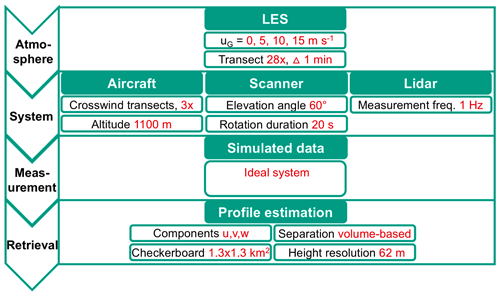
Figure B1Simulator operation scheme and settings for the wind profiling quality analysis. Standard values used for wind profile retrieval are marked in red.
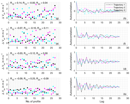
Figure B2Error correlation analysis for the 0 m s−1 background wind case. Panels (a), (c), (e) and (g) show the retrieval errors for every time step at and 760 m altitudes, respectively. The number of the parallel trajectory is color coded. The correlation between neighboring trajectories is additionally given as numbers. Panels (b), (d), (f) and (h) show the autocorrelation of the retrieval errors for each transect.

Figure B6LES truth and ADLS retrieved wind speed components for an ideal measurement system with quality filtering criteria applied. All measurements which pass quality filtering are color coded; grayed out crosses indicate the ones which do not.
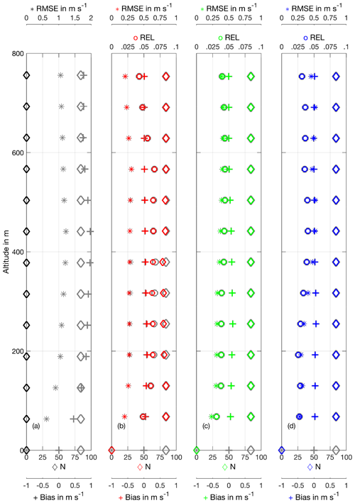
Figure B7Profile of wind speed retrieval quality parameters (RMSE, REL, bias and number of retrieved wind profile points) as a function of height for an ideal system using the standard system setup and retrieval strategy. (a) 0 m s−1 background wind case. Please note the adjusted RMSE display limits. The REL is not displayed because the background wind speed is approximately 0 m s−1, making the REL not meaningful. (b) 5 m s−1 background wind case. (c) 10 m s−1 background wind case. (d) 15 m s−1 background wind case.
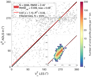
Figure B8LES truth and ADLS retrieved wind direction for an ideal measurement system with quality filtering criteria applied. All measurements which pass quality filtering are color coded; grayed out crosses indicate the ones which do not. Values which pass quality filtering cluster around the 270∘ wind direction, which is magnified in the inset. The 0 m s−1 background wind case is filtered completely by applying quality filtering criteria explained in Sect. 3.4.
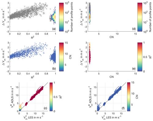
Figure B9Quality filtering criteria for the standard system setup and retrieval strategy. (a) Color-coded histogram of number of occurrences for retrieval error and R2. Gray crosses show values eliminated by quality filtering. (b) Retrieval error and R2; CN is color coded. (c) LES wind speed and ADLS wind speed; R2 is color coded. Profile points which pass quality filtering are displayed as color-coded circles; profile points which are eliminated are shown as color-coded crosses. (d) Same as panel (a) but for CN. (e) Retrieval error and CN; R2 is color coded. (f) Same as panel (c) but for CN.
The underlying MATLAB code and data are available from the author upon request.
PG developed the simulator, performed the simulations, conducted their evaluation and prepared the manuscript, which was improved by all co-authors who acquired the project funding, and also contributed in supervising the work.
The authors declare that they have no conflict of interest.
Christoph Knigge and Siegfried Raasch from the University of Hanover are acknowledged for granting the right to use the LES data. The first author is thankful for PhD supervision by Christoph Kottmeier. We would like to thank Alan Brewer and the anonymous referees for their input during the review process.
The article processing charges for this open-access publication were covered by a Research Centre of the Helmholtz Association.
This paper was edited by Gerd Baumgarten and reviewed by Alan Brewer and three anonymous referees.
Baidar, S., Tucker, S. C., Beaubien, M., and Hardesty, R. M.: The Optical Autocovariance Wind Lidar. Part II: Green OAWL (GrOAWL) Airborne Performance and Validation, J. Atmos. Ocean. Tech., 35, 2099–2116, https://doi.org/10.1175/jtech-d-18-0025.1, 2018. a, b
Baker, W. E., Emmitt, G. D., Robertson, F., Atlas, R. M., Molinari, J. E., Bowdle, D. A., Paegle, J., Hardesty, R. M., Post, M. J., Menzies, R. T., Krishnamurti, T. N., Brown, R. A., Anderson, J. R., Lorenc, A. C., and McElroy, J.: Lidar-Measured Winds from Space: A Key Component for Weather and Climate Prediction, B. Am. Meteorol. Soc., 76, 869–888, 1995. a, b, c
Baker, W. E., Atlas, R., Cardinali, C., Clement, A., Emmitt, G. D., Gentry, B. M., Hardesty, R. M., Källén, E., Kavaya, M. J., Langland, R., Ma, Z., Masutani, M., McCarty, W., Pierce, R. B., Pu, Z., Riishojgaard, L. P., Ryan, J., Tucker, S., Weissmann, M., and Yoe, J. G.: Lidar-measured wind profiles: The missing link in the global observing system, B. Am. Meteorol. Soc., 95, 543–564, https://doi.org/10.1175/BAMS-D-12-00164.1, 2014. a
Banakh, V. A. and Werner, C.: Computer simulation of coherent Doppler lidar measurement of wind velocity and retrieval of turbulent wind statistics, Opt. Eng., 44, 71205, https://doi.org/10.1117/1.1955167, 2005. a
Banakh, V. a., Smalikho, I. N., Köpp, F., and Werner, C.: Representativeness of wind measurements with a cw Doppler lidar in the atmospheric boundary layer, Appl. Optics, 34, 2055–2067, https://doi.org/10.1364/AO.34.002055, 1995. a
Boccippio, D. J.: A diagnostic analysis of the VVP single-doppler retrieval technique, J. Atmos. Ocean. Tech., 12, 230–248, https://doi.org/10.1175/1520-0426(1995)012<0230:ADAOTV>2.0.CO;2, 1995. a, b, c, d, e, f, g, h
Bradley, S., Perrott, Y., Behrens, P., and Oldroyd, A.: Corrections for Wind-Speed Errors from Sodar and Lidar in Complex Terrain, Bound.-Lay. Meteorol., 143, 37–48, https://doi.org/10.1007/s10546-012-9702-0, 2012. a
Bucci, L. R., O'Handley, C., Emmitt, G. D., Zhang, J. A., Ryan, K., and Atlas, R.: Validation of an Airborne Doppler Wind Lidar in Tropical Cyclones, Sensors, 18, 4288, https://doi.org/10.3390/s18124288, 2018. a, b, c, d, e, f
Cheong, B. L., Yu, T. Y., Palmer, R. D., Yang, K. F., Hoffman, M. W., Frasier, S. J., and Lopez-Dekker, F. J.: Effects of wind field inhomogeneities on Doppler beam swinging revealed by an imaging radar, J. Atmos. Ocean. Tech., 25, 1414–1422, https://doi.org/10.1175/2007JTECHA969.1, 2008. a
Chouza, F., Reitebuch, O., Groß, S., Rahm, S., Freudenthaler, V., Toledano, C., and Weinzierl, B.: Retrieval of aerosol backscatter and extinction from airborne coherent Doppler wind lidar measurements, Atmos. Meas. Tech., 8, 2909–2926, https://doi.org/10.5194/amt-8-2909-2015, 2015. a
Chouza, F., Reitebuch, O., Benedetti, A., and Weinzierl, B.: Saharan dust long-range transport across the Atlantic studied by an airborne Doppler wind lidar and the MACC model, Atmos. Chem. Phys., 16, 11581–11600, https://doi.org/10.5194/acp-16-11581-2016, 2016a. a, b, c
Chouza, F., Reitebuch, O., Jähn, M., Rahm, S., and Weinzierl, B.: Vertical wind retrieved by airborne lidar and analysis of island induced gravity waves in combination with numerical models and in situ particle measurements, Atmos. Chem. Phys., 16, 4675–4692, https://doi.org/10.5194/acp-16-4675-2016, 2016b. a, b
Corsmeier, U., Hankers, R., and Wieser, A.: Airborne turbulence measurements in the lower troposphere onboard the research aircraft Dornier 128-6, D-IBUF, Meteorol. Z., 10, 315–329, https://doi.org/10.1127/0941-2948/2001/0010-0315, 2001. a
Davis, C. A., Markowski, P. M., Moore, J. A., Barth, M. C., Grubišić, V., Klein, P. M., Raymond, D. J., Detwiler, A., Geerts, B., Mullendore, G. L., and Lee, W.-C.: Recommendations for In Situ and Remote Sensing Capabilities in Atmospheric Convection and Turbulence, B. Am. Meteorol. Soc., 99, 2463–2470, https://doi.org/10.1175/bams-d-17-0310.1, 2018. a
De Wekker, S. F. J., Godwin, K. S., Emmitt, G. D., and Greco, S.: Airborne Doppler lidar measurements of valley flows in complex coastal terrain, J. Appl. Meteorol. Clim., 51, 1558–1574, https://doi.org/10.1175/JAMC-D-10-05034.1, 2012. a, b, c, d, e, f, g, h
ESA: ESA's Aeolus wind satellite launched, available at: https://www.esa.int/For_Media/Press_Releases/ESA_s_Aeolus_wind_satellite_launched (last access: 18 March 2020), 2018. a
Frehlich, R.: Errors for space-based doppler lidar wind measurements: Definition, performance, and verification, J. Atmos. Ocean. Tech., 18, 1749–1772, https://doi.org/10.1175/1520-0426(2001)018<1749:EFSBDL>2.0.CO;2, 2001. a, b, c
Gamache, J. F., Marks, F. D., and Roux, F.: Comparison of three airborne Doppler sampling techniques with airborne in situ wind observations in Hurricane Gustav (1990), J. Atmos. Ocean. Tech., 12, 171–181, https://doi.org/10.1175/1520-0426(1995)012<0171:COTADS>2.0.CO;2, 1995. a
Godwin, K. S., De Wekker, S. F. J., and Emmitt, G. D.: Retrieving Winds in the Surface Layer over Land Using an Airborne Doppler Lidar, J. Atmos. Ocean. Tech., 29, 487–499, https://doi.org/10.1175/JTECH-D-11-00139.1, 2012. a, b, c
Guimond, S. R., Tian, L., Heymsfield, G. M., and Frasier, S. J.: Wind retrieval algorithms for the IWRAP and HIWRAP airborne doppler radars with applications to hurricanes, J. Atmos. Ocean. Tech., 31, 1189–1215, https://doi.org/10.1175/JTECH-D-13-00140.1, 2014. a, b, c, d, e, f
Haimov, S. and Rodi, A.: Fixed-antenna pointing-angle calibration of airborne doppler cloud radar, J. Atmos. Ocean. Tech., 30, 2320–2335, https://doi.org/10.1175/JTECH-D-12-00262.1, 2013. a, b
Holleman, I.: Quality control and verification of weather radar wind profiles, J. Atmos. Ocean. Tech., 22, 1541–1550, https://doi.org/10.1175/JTECH1781.1, 2005. a, b
Kavaya, M. J., Beyon, J. Y., Koch, G. J., Petros, M., Petzar, P. J., Singh, U. N., Trieu, B. C., and Yu, J.: The doppler aerosol wind (DAWN) airborne, wind-profiling coherent-detection lidar system: Overview and preliminary flight results, J. Atmos. Ocean. Tech., 31, 826–842, https://doi.org/10.1175/JTECH-D-12-00274.1, 2014. a, b
Kiemle, C., Wirth, M., Fix, A., Rahm, S., Corsmeier, U., and Di Girolamo, P.: Latent heat flux measurements over complex terrain by airborne water vapour and wind lidars, Q. J. Roy. Meteor. Soc., 137, 190–203, https://doi.org/10.1002/qj.757, 2011. a
Klaas, T., Pauscher, L., and Callies, D.: LiDAR-mast deviations in complex terrain and their simulation using CFD, Meteorol. Z., 24, 591–603, https://doi.org/10.1127/metz/2015/0637, 2015. a
Koch, G. J., Beyon, J. Y., Cowen, L. J., Kavaya, M. J., and Grant, M. S.: Three-dimensional wind profiling of offshore wind energy areas with airborne Doppler lidar, J. Appl. Remote Sens., 8, 1–11, https://doi.org/10.1117/1.JRS.8.083662, 2014. a
Koscielny, A.: An Evaluation of the Accuracy of Some Radar Wind Profiling Techniques, J. Atmos. Ocean. Tech., 1, 309–320, 1984. a
Lenschow, D. H.: The Measurement of Air Velocity and Temperature Using the NCAR Buffalo Aircraft Measuring System, Tech. Rep. June, NCAR, Boulder, 1972. a, b
Leon, D. and Vali, G.: Retrieval of three-dimensional particle velocity from airborne doppler radar data, J. Atmos. Ocean. Tech., 15, 860–870, https://doi.org/10.1175/1520-0426(1998)015<0860:ROTDPV>2.0.CO;2, 1998. a, b, c, d, e, f, g
Lorsolo, S., Gamache, J., and Aksoy, A.: Evaluation of the hurricane research division doppler radar analysis software using synthetic data, J. Atmos. Ocean. Tech., 30, 1055–1071, https://doi.org/10.1175/JTECH-D-12-00161.1, 2013. a
Lundquist, J. K., Churchfield, M. J., Lee, S., and Clifton, A.: Quantifying error of lidar and sodar Doppler beam swinging measurements of wind turbine wakes using computational fluid dynamics, Atmos. Meas. Tech., 8, 907–920, https://doi.org/10.5194/amt-8-907-2015, 2015. a
Lux, O., Lemmerz, C., Weiler, F., Marksteiner, U., Witschas, B., Rahm, S., Schäfler, A., and Reitebuch, O.: Airborne wind lidar observations over the North Atlantic in 2016 for the pre-launch validation of the satellite mission Aeolus, Atmos. Meas. Tech., 11, 3297–3322, https://doi.org/10.5194/amt-11-3297-2018, 2018. a
Menke, W.: Describing Inverse Problems, Elsevier/Academic Press, Oxford UK, https://doi.org/10.1016/B978-0-12-397160-9.00001-1, 2012. a
Muschinski, A., Sullivan, P. P., Wuertz, D. B., Hill, R. J., Cohn, S. A., Lenschow, D. H., and Doviak, R. J.: First synthesis of wind-profiler signals on the basis of large-eddy simulation data, Radio Sci., 34, 1437–1459, https://doi.org/10.1029/1999RS900090, 1999. a
Paffrath, U., Lemmerz, C., Reitebuch, O., Witschas, B., Nikolaus, I., and Freudenthaler, V.: The airborne demonstrator for the direct-detection doppler wind lidar aladin on adm-aeolus. Part II: Simulations and rayleigh receiver radiometric performance, J. Atmos. Ocean. Tech., 26, 2516–2530, https://doi.org/10.1175/2009JTECHA1314.1, 2009. a
Päschke, E., Leinweber, R., and Lehmann, V.: An assessment of the performance of a 1.5 µm Doppler lidar for operational vertical wind profiling based on a 1-year trial, Atmos. Meas. Tech., 8, 2251–2266, https://doi.org/10.5194/amt-8-2251-2015, 2015. a, b, c, d, e, f
Pauscher, L., Vasiljevic, N., Callies, D., Lea, G., Mann, J., Klaas, T., Hieronimus, J., Gottschall, J., Schwesig, A., Kühn, M., and Courtney, M.: An inter-comparison study of multi- and DBS lidar measurements in complex terrain, Remote Sens., 8, 782, https://doi.org/10.3390/rs8090782, 2016. a
Raasch, S. and Schröter, M.: PALM - A large-eddy simulation model performing on massively parallel computers, Meteorol. Z., 10, 363–372, https://doi.org/10.1127/0941-2948/2001/0010-0363, 2001. a
Scipion, D.: Characterization of the convective boundary layer through a combination of large-eddy simulations and a radar simulator, Phd, University of Oklahoma, 2011. a
Scipión, D., Palmer, R., Chilson, P., Fedorovich, E., and Botnick, A.: Retrieval of convective boundary layer wind field statistics from radar profiler measurements in conjunction with large eddy simulation, Meteorol. Z., 18, 175–187, https://doi.org/10.1127/0941-2948/2009/0371, 2009. a
Shenghui, Z., Ming, W., Lijun, W., Chang, Z., and Mingxu, Z.: Sensitivity analysis of the VVP wind retrieval method for single-doppler weather radars, J. Atmos. Ocean. Tech., 31, 1289–1300, https://doi.org/10.1175/JTECH-D-13-00190.1, 2014. a, b
Stawiarski, C.: Optimizing Dual-Doppler Lidar Measurements of Surface Layer Coherent Structures with Large-Eddy Simulations, KIT Scientific Publishing, Karlsruhe, 2014. a
Stawiarski, C., Traumner, K., Knigge, C., and Calhoun, R.: Scopes and challenges of dual-doppler lidar wind measurements-an error analysis, J. Atmos. Ocean. Tech., 30, 2044–2062, https://doi.org/10.1175/JTECH-D-12-00244.1, 2013. a, b, c, d, e
Stawiarski, C., Träumner, K., Kottmeier, C., Knigge, C., and Raasch, S.: Assessment of Surface-Layer Coherent Structure Detection in Dual-Doppler Lidar Data Based on Virtual Measurements, Bound.-Lay. Meteorol., 156, 371–393, https://doi.org/10.1007/s10546-015-0039-3, 2015. a, b, c
Tian, L., Heymsfield, G. M., Didlake, A. C., Guimond, S., and Li, L.: Velocity-Azimuth display analysis of doppler velocity for HIWRAP, J. Appl. Meteorol. Clim., 54, 1792–1808, https://doi.org/10.1175/JAMC-D-14-0054.1, 2015. a, b, c, d, e, f
Tucker, S. C., Weimer, C. S., Baidar, S., and Hardesty, R. M.: The optical autocovariance wind lidar. Part I: OAWL instrument development and demonstration, J. Atmos. Ocean. Tech., 35, 2079–2097, https://doi.org/10.1175/JTECH-D-18-0024.1, 2018. a
Wainwright, C. E., Stepanian, P. M., Chilson, P. B., Palmer, R. D., Fedorovich, E., and Gibbs, J. A.: A time series sodar simulator based on large-eddy simulation, J. Atmos. Ocean. Tech., 31, 876–889, https://doi.org/10.1175/JTECH-D-13-00161.1, 2014. a, b, c
Waldteufel, P. and Corbin, H.: On the Analysis of Single-Doppler Radar Data, J. Appl. Meteorol., 18, 532–542, https://doi.org/10.1175/1520-0450(1979)018<0532:OTAOSD>2.0.CO;2, 1978. a
Wang, H., Barthelmie, R. J., Clifton, A., and Pryor, S. C.: Wind measurements from arc scans with Doppler wind lidar, J. Atmos. Ocean. Tech., 32, 2024–2040, https://doi.org/10.1175/JTECH-D-14-00059.1, 2015. a, b, c, d, e, f
Weissmann, M., Busen, R., Dörnbrack, A., Rahm, S., and Reitebuch, O.: Targeted observations with an airborne wind lidar, J. Atmos. Ocean. Tech., 22, 1706–1719, https://doi.org/10.1175/JTECH1801.1, 2005. a, b, c, d, e, f, g, h, i, j
Weitkamp, C., Asakura, T., Ha, T. W., Kamiya, T., Krausz, F., Monemar, B., Venghaus, H., Weber, H., and Weinfurter, H.: Lidar – Range-Resolved Optical Remote Sensing of the Atmosphere, Springer, New York, NY, 2005. a
Witschas, B., Rahm, S., Dörnbrack, A., Wagner, J., and Rapp, M.: Airborne wind lidar measurements of vertical and horizontal winds for the investigation of orographically induced gravity waves, J. Atmos. Ocean. Tech., 34, 1371–1386, https://doi.org/10.1175/JTECH-D-17-0021.1, 2017. a, b
Zhang, J., Atlas, R., Emmitt, G., Bucci, L., and Ryan, K.: Airborne Doppler Wind Lidar Observations of the Tropical Cyclone Boundary Layer, Remote Sens., 10, 825, https://doi.org/10.3390/rs10060825, 2018. a, b
- Abstract
- Introduction
- Airborne Doppler lidar simulator
- Airborne Doppler lidar wind profiling in inhomogeneous flow conditions
- Conclusions
- Appendix A: Mathematical formulation of concepts implemented in the ADLS
- Appendix B: Additional figures
- Code and data availability
- Author contributions
- Competing interests
- Acknowledgements
- Financial support
- Review statement
- References


