the Creative Commons Attribution 4.0 License.
the Creative Commons Attribution 4.0 License.
 | 17 Apr 2024
Development of a cascade impactor optimized for size-fractionated analysis of aerosol metal content by total reflection X-ray fluorescence spectroscopy (TXRF)
Claudio Crazzolara
Andreas Held
A new cascade impactor has been developed with the arrangement of the classifying nozzles optimized for analysis of the collected particles by total reflection X-ray fluorescence (TXRF). TXRF offers detection limits in the range of a few picograms of absolute mass and therefore poses great potential for the elemental analysis of heavy metals in aerosol particles. To fully exploit this high sensitivity, particles have to be collected in the effective analysis area of the TXRF instrument, which is often smaller than typical deposition patterns of commercial impactors or filter samplers. This is achieved by a novel compact arrangement of the classifying nozzles within a circular area of a diameter of less than 5 mm. A decreasing density of the nozzle spacing from the inside to the outside of the nozzle cluster allows for constant cross-flow conditions, minimizing the mutual influence of the individual nozzles. The design of a multistage cascade impactor is presented to individually sample PM10, PM2.5 and PM1 size fractions. Considering the high sensitivity of TXRF analysis, constructive measures have been taken to prevent attrition of impactor material which might lead to methodical blank values. Experimental validation confirms that neither attrition nor cross-contamination can be observed. Furthermore, a new spin-coating method has been developed which makes it possible to apply a thin and defined adhesive layer of grease to the sample carrier with good repeatability. Application of the impactor in a case study at an urban site at Potsdamer Platz, Berlin, Germany, shows that sampling at a moderate volume flow rate of 5 L min−1, the particle mass collected in 30 min or less is sufficient for reliable TXRF analysis of heavy metal concentrations (Fe, Zn, Cu, Mn, Pb and Ni) in ambient aerosol. This high time resolution enables snapshot sampling, e.g. to quantify variations in particle source strengths. Overall, the new impactor optimized for TXRF analysis bears great potential to improve the quantification of particulate trace metals and other elements in PM10, PM2.5 and PM1 with high time resolution.
- Article
(3324 KB) - Full-text XML
-
Supplement
(598 KB) - BibTeX
- EndNote


Air pollution caused by aerosol particles has detrimental impacts on humans, animals and plants (Fuzzi et al., 2015). Airborne particles with an aerodynamic diameter of less than 10 µm have been associated with adverse health effects in numerous studies (Chen and Hoek, 2020). Fine particles with an aerodynamic diameter of less than 2.5 µm can penetrate deep into the body via the respiratory tract and are generally associated with a greater risk potential than coarse particles (e.g. Feng et al., 2016). Therefore, the World Health Organization has recommended and many countries have imposed legal limits for the mass concentration of health-relevant size fractions of particulate matter such as PM10 and PM2.5 (e.g. WHO, 2021; European Parliament, 2008). In addition, the chemical composition of aerosol particles is important with regard to element-specific hazard potentials (Corriveau et al., 2011), and target values for the mass content of certain elements have been introduced (European Parliament, 2004). The European standard method EN 14902:2005 for measuring lead, arsenic, cadmium and nickel in the PM10 fraction requires particle collection on filters, sample digestion and elemental analysis by graphite furnace atomic absorption spectroscopy, or inductively coupled plasma mass spectrometry (CEN, 2005). This offline approach is rather time-consuming and does not allow for studying transient concentration changes with high time resolution.
Fast and sensitive elemental analysis of size-fractionated aerosol samples is possible with a combination of impactor sampling and total reflection X-ray fluorescence spectroscopy (TXRF). Impactor sampling of aerosol particles is commercially available and widely used (Marple, 2004). Elemental analysis of collected aerosol particles has often been done by inductively coupled plasma mass spectrometry (e.g. Gietl et al., 2010) or X-ray fluorescence (XRF; e.g. Kuhn et al., 2005) and TXRF (e.g. Schneider, 1989). In XRF and TXRF, the sample is excited with X-ray radiation, and the resulting fluorescence is characteristic of individual chemical elements in the sample. In TXRF, the sample is prepared on a flat sample carrier with a polished surface. A polychromatic X-ray beam is monochromatized and irradiates the sample at a very shallow angle of approximately 0.1°, which leads to total reflection of the incident X-ray beam at the surface of the sample carrier. Fluorescence radiation from the sample is analysed with a detector located directly above the sample with a large solid angle of view. The effective analysis area results from the superposition of the area that is excited by the X-ray beam and the field of view of the detector. Since there is almost no interaction between the exciting X-ray beam and the substrate of the sample carrier, the signal-to-noise ratio is significantly improved compared to conventional XRF. As a result, the detection limit of TXRF is superior to that of XRF (Yoneda and Horiuchi, 1971) and can reach down to a few picograms of absolute mass on the sample carrier substrate (Streli, 2006). Even detection limits in the range of femtograms (10−15 g) can be achieved with TXRF analysis (Eichert, 2020), and also light elements (with a low Z number) can be excited effectively by synchrotron radiation excitation of the sample (Beckhoff et al., 2007; Streli et al., 2008). Recently, Prost et al. (2017) and Seeger et al. (2021) demonstrated the huge potential of TXRF analysis for the elemental analysis of aerosol particles collected with a commercial impactor, in particular for sampling times of a few hours only. Despite promising results, commercial impactors are not fully optimized for TXRF analysis; the area on the sample carrier in which the classifying nozzles deposit the particles is usually significantly larger than the area analysed by TXRF. As a result, only a fraction of the particles collected by the impactor is actually analysed, while a significant proportion of the impacted particles remains inaccessible for the TXRF analysis. Consequently, the overall sensitivity is reduced. To take full advantage of the high detection sensitivity of TXRF analysis, it is necessary to analyse the entire sample collected by the impactor.
Here, we present the development of a cascade impactor optimized for size-fractionated analysis of aerosol metal content by TXRF. The target application of the newly developed impactor is to quantify low concentrations of heavy metals in atmospheric aerosol samples collected over periods of 1 h or less. The impactor is designed (1) to collect particles in individual size fractions to quantify the metal content in PM10, PM2.5 and PM1 separately; (2) to collect particles in circular areas with a diameter of approximately 5 mm or less in the centre of the sample carrier for a full TXRF analysis; and (3) to provide low blank values and minimum cross-contamination between subsequent sampling periods. The impactor nozzles of the new cascade impactor are arranged in such a way that all particles collected on the respective sample carrier contribute to the TXRF analysis, thus increasing the overall sensitivity. This enables shorter sampling times, which in turn opens up new possibilities for identifying pollutant sources. The corresponding arrangement of the impactor nozzles could not be achieved simply by compressing a previous deposition pattern, but rather the number and lateral arrangement, as well as the diameters of the impactor nozzles, have to be recalculated. As a result of these considerations, the new cascade impactor is designed for a reduced gas mass flow compared to commercially available impactors, which in turn enables the use of smaller pumps and thus portable and mobile battery-powered operation of the impactor in the field. We first present the general impactor design, the nozzle arrangement and an improved coating method for sample carriers. After describing the experimental procedures to validate the impactor performance and the first application of the impactor in outdoor air, we present and discuss the experimental results.
2.1 General impactor design
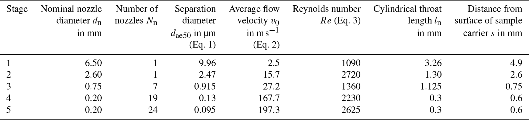
For size-fractionated elemental analysis of PM10, PM2.5 and PM1, the relevant particle size fractions must be collected individually. At the same time, particles should be collected on as few impactor stages as possible to simplify handling and to increase the absolute particle mass on individual stages. These considerations imply a configuration of three stages with 50 % separation diameters of 10.0, 2.5 and 1 µm, respectively, and a fourth stage with a separation diameter well below 1 µm so that almost all particles contributing to PM1 in terms of mass are collected. Previous TXRF analysis results of impactor samples (e.g. Seeger et al., 2021) suggest that particles of a diameter of 0.1 µm or less make only a minor contribution to particulate mass assuming a typical outdoor aerosol size distribution with significant contributions of the accumulation mode and coarse modes. Therefore, a fourth stage with a separation diameter of approximately 0.1 µm can be used to collect almost the entire PM1 fraction. In the present study, we apply a fourth stage with a nominal separation diameter of 0.13 µm and a fifth stage with a nominal separation diameter of 0.095 µm for experimental purposes. In special circumstances it might be important to collect ultrafine particles with, for example, an additional impactor stage with a separation diameter of e.g. 0.02 or 0.01 µm, as outlined in Sect. 5 of the paper, or alternatively a final filter stage.
An optimized impactor design allows particle collection directly on the sample carriers for TXRF analysis, providing compact deposition patterns in circular areas with diameters smaller than 5 mm. This compact deposition pattern is achieved by choosing a low flow rate of 5 standard litres per minute (slpm; equivalent to volume flow in standard conditions, that is 1013 hPa and 20 °C), which allows single classifying nozzles to be used during stages 1 and 2 (separation diameters of 10 and 2.5 µm) and multiple nozzles located in a circular area with a diameter of less than 5 mm during stages 3–5, without exceeding a critical Reynolds number of 3000.
Each impactor stage has an upper body accommodating the classifying nozzles and a lower body accommodating the sample carrier (Fig. 1a). The classifying nozzles are incorporated in an exchangeable nozzle module (Fig. 1b), which defines the number N, diameter dn, length ln and lateral separation dlat of the classifying nozzles, as well as the distance s between the end of the nozzle and the surface of the sample carrier. These parameters have an influence on the separation diameter and the separation characteristics of the impactor stage. The sample carrier is fixed by means of an elastic mounting ring made from laser-sintered polyamide. Due to this modular design, the number of impactor stages can be easily adapted to different applications to allow for different separation diameters and size-fractionated samples. When designing the modules, care was taken to guide the flow through the impactor with as little interference as possible to minimize particle losses.
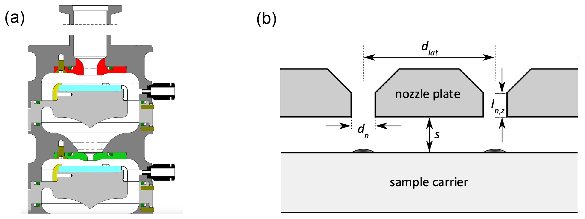
Figure 1(a) Schematic of the first two impactor stages, with an upper body (dark grey) accommodating the nozzle module (red and green), a non-metallic mounting ring (olive) for fixing the sample carrier and a lower body (light grey) accommodating the sample carrier (light blue). (b) Cross section of a nozzle module with two adjacent nozzles and the sample carrier.
To assemble the impactor, the modules are stacked on top of each other into a support frame to form a cascade. Two pushrod clamps compress the sealing rings between the modules. Care was taken to minimize metal-to-metal friction during the assembly and disassembly of the impactor, which might contaminate samples with metal particles with regard to the high sensitivity of the TXRF analysis. A locking pin prevents the modules from rotating in the stacked state, and a sealing ring positioned internally prevents particles from entering the impactor chamber in case a small amount of attrition were to occur at the metallic mating surfaces during assembly. In addition, the inner surfaces of the impactor have been polished electrically after machining to minimize surface roughness and facilitate cleaning.
2.2 Geometry and arrangement of the classifying nozzles
The geometry and number of the classifying nozzles were designed according to Marple and Willeke (1976). The aerodynamic 50 % separation diameter dae50 of an impactor stage can be expressed as a function of the nozzle diameter dn:
where η is the dynamic viscosity of the air (η = 1.81 × 10⁻² at 20 °C), Cc is the Cunningham slip correction factor (Allen and Raabe, 1982, 1985), ρp is the particle density (ρp = 1 × 10⁶g m−3 by definition of aerodynamic diameter), v0 is the average flow velocity in the nozzle and St50 is the critical Stokes number. For impactor stages with a single circular nozzle, the value St50 = 0.24 can be assumed (Rader and Marple, 1985), and for impactors with multiple circular nozzles, the value St50 = 0.216 was determined experimentally (Hillamo and Kauppinen, 1991). The average flow velocity in the nozzle v0 is a function of the volumetric flow rate Q, the nozzle diameter dn and the number of nozzles Nn:
It is important to note that while the mass flow rate through the impactor is constant, e.g. 5 slpm corresponding to a volumetric flow rate of 5 L min−1 in standard conditions (1013 hPa and 20 °C), the actual volumetric flow rate Q increases downstream with each impactor stage as a result of the pressure drop and the associated expansion of the gas. The number of nozzles Nn per classification stage was selected so that the Reynolds number Re calculated according to Eq. (3) does not exceed a value of 3000 in each individual nozzle.
where ρair is the density of air (ρair = 1204 g m−3 at 20 °C). In Table 1, the nominal nozzle diameter dn and the number of nozzles Nn for each separation stage are indicated along with the calculated separation diameter dae50 according to Eq. (1), the average flow velocity v0 according to Eq. (2), the Reynolds number Re according to Eq. (3), the cylindrical throat length ln, and the distance between the end of the nozzle and the surface of the sample carrier s. At the impactor stages 1 and 2, the classifying nozzles exhibit a bell-mouth-shaped inlet that tapers to the nozzle diameter. The classifying nozzles in stages 3–5 have a conical taper at the inlet with an opening angle of 90° (Fig. 1b). Since a parabolic flow profile is formed in a pipe in laminar flow conditions only at some distance from the pipe inlet, long classifying nozzles favour the development of a parabolic, pipe-like flow profile, resulting in a less steep separation curve. Therefore, the cylindrical throat length of the classifying nozzles ln was kept short in order to facilitate the formation of a plug-shaped flow profile. The ratio of the length ln to the diameter dn of the cylindrical section of the nozzle is kept between 0.5 (stage 1) and 1.5 (stages 4 and 5). The distance s between the nozzle end and the sample carrier should be kept as small as possible with regard to the steepness of the separation efficiency curve; however, it must be sufficiently large to allow the airflow to escape unhindered radially to the direction of flow through the classifying nozzle (Marple et al., 1991). Short distances also enhance the blow-off of impacted particles. The distances s are between 4.9 mm (stage 1) and 0.6 mm (stages 4 and 5).
Table 1Design parameters of the five separation stages of the newly developed cascade impactor.
In stages 3 to 5, multiple classifying nozzles were required to realize small separation diameters with Re < 3000. If the lateral distance dlat between several classifying nozzles is too small, the separation characteristics may be affected. This can occur due to an interference of the outflow of two adjacent classifying nozzles colliding and causing a secondary impaction, resulting in a “tailing” of the separation curve towards smaller particle diameters (García-Ruiz et al., 2019a, b). Hence, it is important to establish an optimum distance between nozzles that allows a compact deposition pattern but at the same time does not strongly influence the separation characteristics of the impactor stages. Fang et al. (1991) developed a method for estimating the extent of cross flow by calculating the cross-flow parameter kcf:
where Nn is the number of nozzles in the nozzle cluster; dn is the individual nozzle diameter; and dc is the diameter of the nozzle cluster, i.e. the circular area where the nozzles are arranged. Empirical particle collection data show that impactor stages with multiple nozzles operate satisfactorily if the value of the cross-flow parameter kcf is lower than a critical value of 1.2 (Fang et al., 1991).
To meet this challenge, we have developed a special arrangement of the classifying nozzles in which the distance between adjacent nozzles increases from the centre of the nozzle cluster towards its outer edge. This ensures that all nozzles are operated in the same cross-flow conditions and that the radial outflow does not exceed a maximum cross-flow velocity. In the classifying nozzle arrangement of stages 3–5 (dc = 3, 3.6 and 4.2 mm) of our impactor, the corresponding cross-flow parameters kcf according to Eq. (4) are 0.44, 0.27 and 0.31, respectively, and thus well below the critical value of 1.2 determined by Fang et al. (1991). An exemplary illustration of the distribution of the cross-flow velocity of the nozzle cluster of stage 4 can be found in Fig. S1 in the Supplement.
Figure 2 shows scanning electron microscopic (SEM) images with perspective views of all 19 classifying nozzles on both sides of the nozzle module of stage 4 and an enlarged view of a single classifying nozzle. On the high-pressure side (Fig. 2a and b), the conical sections of the classifying nozzles can be seen, where the diameter tapers from 500 to 200 µm in the direction of the gas flow, followed by the circular cylindrical section to the end of the classifying nozzles on the low-pressure side (Fig. 2c and d).
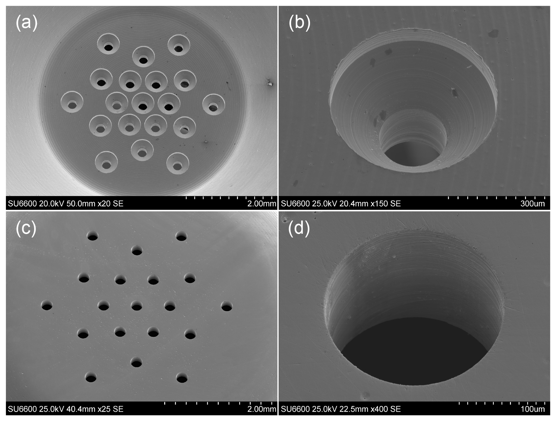
Figure 2Scanning electron microscopic (SEM) images of the nozzle module of stage 4 with perspective views of (a) all classifying nozzles and (b) a single classifying nozzle on the high-pressure side and (c) all classifying nozzles and (d) a single classifying nozzle on the low-pressure side.
Measuring the inner diameters of the classifying nozzles with a light optical measuring microscope (Keyence IM-7000) resulted in relative deviations of only a few percent in relation to the respective nominal diameters (Table S1 in the Supplement). These measurements reflect highly uniform diameters of the individual classifying nozzles of the multi-nozzle impactor stages 3 to 5.
2.3 Spin coating of sample carriers
Depending on the application, it is common practice to apply an adhesive layer to the impaction substrate (Injuk and Grieken, 1995). This adhesive layer prevents effects such as bounce-off or blow-off of impacted particles from the impaction substrate. Silicon-based polymers like polysiloxane silicone oils or hydrocarbon-based greases can be used as adhesives. Here, the silicone- and halogen-free ultra-high vacuum grease Apiezon L (M&I Materials Limited) is utilized, which is characterized by low vapour pressure, low creep or carryover, and high purity. For TXRF analysis, Apiezon L is virtually blank-value-free except for low blank values of sulfur, iron and bromine.
Up to now the adhesive layer has been applied onto the impaction substrate by dabbing or brushing (Injuk and Van Grieken, 1995; Streli, 2006), by spraying (Seeger et al., 2021), or by impacting out of an aerosol (Hillamo and Kauppinen, 1991). For TXRF analysis, it is necessary that the adhesive layer is applied to the sample carriers in a reproducible manner and without local inhomogeneities of the layer thickness. In addition, the layer should be as thin as possible so that it does not induce a background signal in the fluorescence spectrum. Therefore, a spin-coating process was developed, which ensures a uniform and flat adhesive layer on the surface of the sample carrier. Firstly, 10 g of Apiezon L grease is dissolved in 100 mL of toluene. The resulting opaque yellow solution is filtered through a syringe filter with a pore size of 0.2 µm to obtain a clear yellow solution. Then, 15 µL of the filtered, clear yellow solution is taken up by a pipette and applied to the centre of the sample carrier, which is rotating at a speed of 6000 rpm. The excess solution is spun and a thin layer of the solution remains on the sample carrier. Within a short time of approximately 0.5 s, the toluene volatilizes, and a homogeneous layer of Apiezon L remains on the surface of the sample carrier. The layer thickness can be varied by the mass fraction of grease in the solution and by the speed of rotation of the sample carrier during spin coating.
3.1 Experimental procedures to validate impactor performance
3.1.1 Blank values due to particle attrition or adhesive coating
In the process of assembly and disassembly of the impactor, particle attrition can occur due to metal-to-metal friction. If these particles settle on the collection substrate, a blank value may result during TXRF analysis. Klockenkämper et al. (1995) report blank values of 40 % on average for stainless-steel impactors in relation to the actual measured value. All metal parts of the impactor developed in the present study are made from chrome–nickel steel (type 1.4301 X5CrNi18-10), which contains mainly iron and additionally 18 % chromium, 10 % nickel, a maximum of 2.0 % manganese and a maximum of 1 % silicon. The sealing rings are made of fluoropolymer, the elastic locking rings are made of polyamide and the screws of the nozzle modules are made of stainless steel. Any attrition could release particles of the abovementioned composition. In addition, non-metallic tweezers were used to manipulate the sample carriers, and even beyond that, undesirable metallic contamination of the sample carriers was avoided by careful handling. To determine the potential of contamination due to attrition, the following experimental procedure was carried out in a clean-room environment.
First, the impactor was disassembled into its individual parts, cleaned and dried. After cleaning, sample carriers made from SiO2 glass were installed. Prior to installation, these sample carriers were cleaned and then subjected to a TXRF analysis (TXRF no. 1). Regarding this experiment, all TXRF analyses were performed for a duration of 1000 s using MoKα excitation. After the installation of the sample carriers, the impactor stages were assembled and tensioned with the pushrod clamps. In this state, the impactor would be ready for particle collection. Instead, the pushrod clamps were relaxed again, and the impactor was disassembled, preparing the extraction of the sample carriers for analysis. This assembly–disassembly procedure was repeated five times to provoke particle attrition and deposition onto the sample carriers. Afterwards, the sample carriers were removed and analysed (TXRF no. 2). Subsequently, the sample carriers were spin-coated with an adhesive film and analysed by TXRF (TXRF no. 3) thereafter to determine the influence of impurities and possible blank values in the adhesive coating. The coating is intended to retain any particles that may have formed. Next, the coated sample carriers were mounted, and the assembly–disassembly procedure was repeated five times. The impactor was then operated for 5 min at a volumetric flow rate of 5 slpm, with the air sampled taken from a particle-free environment. This was done to agitate any particles that may have formed inside the impactor, depositing them on the sample carriers by impaction. The impactor was then disassembled, and the sample carriers were removed and analysed using TXRF (TXRF no. 4).
3.1.2 Cross-contamination between subsequent sampling periods
Particles may be deposited on the inner surfaces of the impactor during aerosol sampling. In a subsequent sampling operation, these particles may be resuspended from the wall and deposited on the sample carriers, thus affecting the result of the analysis. The error caused by this potential “memory” effect may amount to an average of 30 % in relation to the actual value, as reported by Klockenkämper et al. (1995). Thorough cleaning after each particle collection operation can help to avoid this cross-contamination error but is time-consuming and a large effort.
To prevent cross-contamination, the flow chamber of our impactor was designed with large curvature radii to avoid abrupt changes along the flow path as much as possible. In addition, the surface roughness was reduced by electrolytic polishing of internal surfaces. To investigate the effectiveness of these design measures, the following experiments were carried out.
First, sample carriers (SiO2 glass) were cleaned and coated with an adhesive film using the spin-coating method described in Sect. 2.3. Subsequently, blank spectra of the coated sample carriers were recorded (TXRF no. 5). For this purpose, the element iron was evaluated, as in many cases it is the most abundant heavy metal in the fine-particle fraction. The coated sample carriers were then placed in a cleaned impactor, and the impactor was operated for 5 min with filtered, particle-free air at a flow rate of 5 slpm. Next, the sample carriers were analysed again (TXRF no. 6), evaluating whether particles detach from the wall of the flow chamber during the 5 min operation of the impactor. The same sample carriers were installed in the impactor again, and the impactor was operated for 30 min with particle-laden atmospheric air and a flow rate of 5 slpm. During this collection operation, the particle mass concentration of the atmospheric air was measured in three size fractions (PM10, PM2.5 and PM1) using an optical aerosol spectrometer (Fidas Frog by Palas GmbH, Karlsruhe, Germany), which was previously warmed up for 120 min and adjusted using calibration dust (MonoDust by Palas GmbH, Karlsruhe, Germany). Following the 30 min collection run, the particle-laden sample carriers were removed from the impactor and subjected to further TXRF analysis (TXRF no. 7). To determine whether subsequent sampling with this possibly contaminated impactor would result in cross-contamination due to resuspension of particles deposited on the walls of the impactor, spectra were recorded from additional, clean and coated SiO2 glass sample carriers (TXRF no. 8). These sample carriers were then placed in the potentially particle-contaminated impactor and operated for 15 min with filtered, particle-free air at a flow rate of 5 slpm. Ultimately the sample carriers were removed from the impactor and subjected to TXRF analysis (TXRF no. 9) to determine whether the particle load of the sample carriers had increased, i.e. whether cross-contamination had occurred.
3.2 Particle collection in outdoor air
Particles from atmospheric air were collected on SiO2 glass sample carriers during three consecutive sampling periods using the newly developed impactor and a mobile battery-operated pump unit. Due to the low volume flow of 5 L min−1 in standard conditions, the impactor can be operated with a simple diaphragm vacuum pump (N 813.3 by KNF Neuberger GmbH, Freiburg, Germany) powered by a rechargeable Li-ion battery. A mass flow sensor (SFM4300-20-P by Sensirion AG, Stäfa, Switzerland) is applied to measure the gas mass flow through the impactor. The sensor is factory-calibrated, has an operating temperature range of +5 to +50 °C and provides a temperature-compensated output signal. Figure 3 shows the impactor and the pump unit during operation in the field.
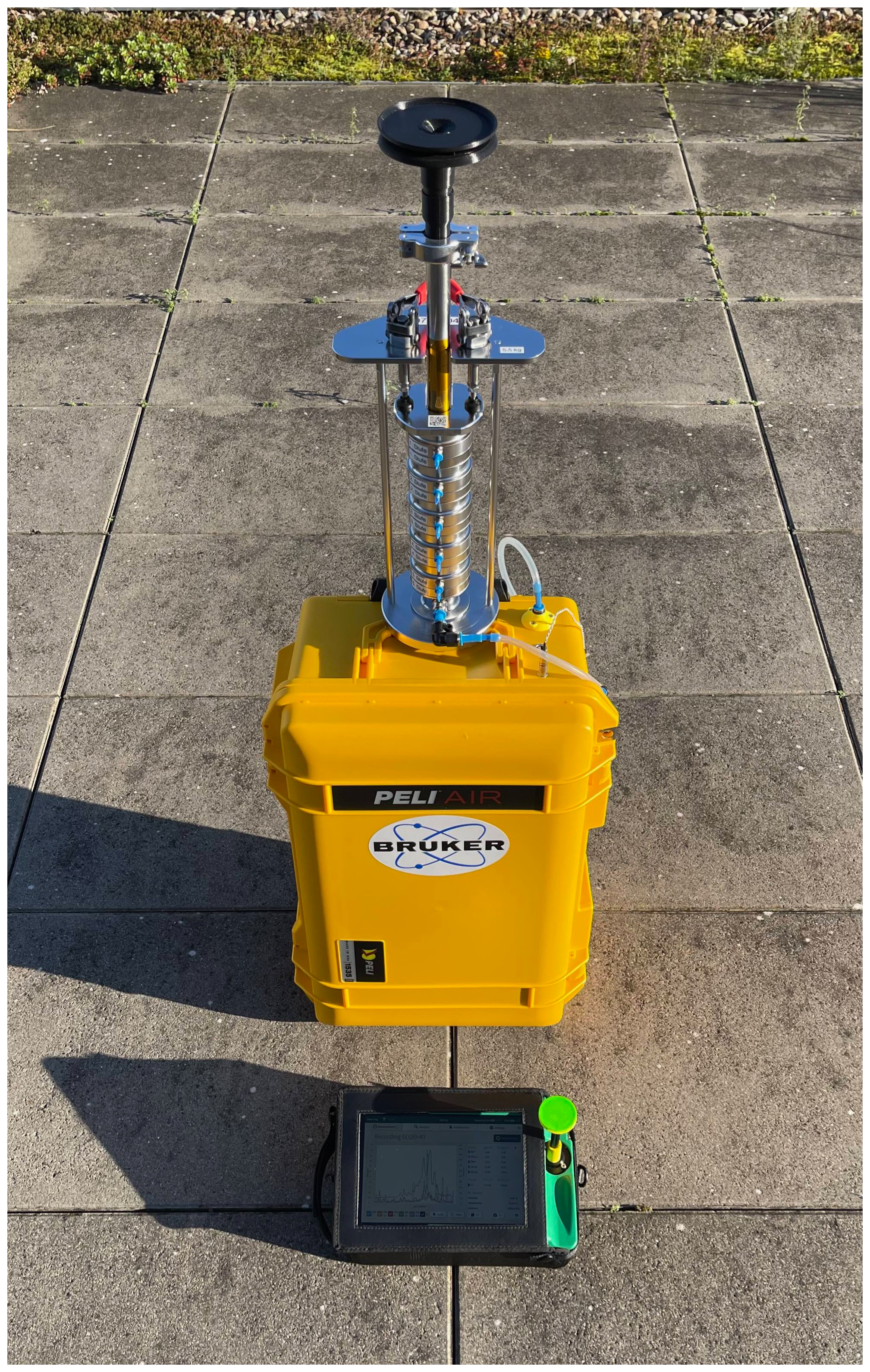
Figure 3Impactor with five impactor stages in assembled condition with omnidirectional air intake (black) placed on the yellow transport case containing the pump and a rechargeable battery; Fidas Frog aerosol spectrometer is on the ground next to the particle sampling unit.
The impactor was located next to the road intersection of Potsdamer Platz (52.50926° N, 13.37699° E), an urban roadside environment in Berlin, Germany. Particle collection was carried out on 29 August 2022 in the morning between 08:00 and 09:36 central European summer time (CEST; the time zone for all instances in the text is CEST) in three consecutive collection periods, lasting for 30 min each. The first period lasted from 08:00 to 08:30, the second period from 08:32 to 09:02 and the third period from 09:06 to 09:36. With an air mass flow rate of 5 slpm, a total volume of 150 L (in standard conditions, that is 293 K and 1013 hPa) was sampled in each individual 30 min collection period. Between the collection periods, the impactor was reloaded with plain, greased sample carriers, and the loaded sample carriers were packed for transport to the laboratory and subsequent TXRF analysis.
3.3 TXRF analysis
For the chemical analysis of particles collected on the sample carriers, a Bruker S4 T-STAR TXRF spectrometer (Bruker Nano GmbH, Berlin, Germany) was applied. The main components of the instrument are shown schematically in Fig. 4. The TXRF spectrometer comprises two air-cooled X-ray tubes, each with an electrical power of 50 W. In one tube, molybdenum is used as anode material, and tungsten is used in the other tube. By applying three multilayer monochromators, the excitation energy can be adjusted to 17.5 keV (molybdenum–K), 8.5 keV (tungsten–L) or 35 keV (tungsten–Brems). The detector is a Peltier-cooled energy-dispersive silicon drift detector (SDD) with an active area of 60 mm2. Circular discs of a diameter of 30 mm and a thickness of 3 mm are used as sample carriers. A circular area with a diameter of approximately 5 mm in the centre of the sample carrier is the effective analysis area, which results from the superposition of the area excited by the X-ray beam, namely a rectangular area with a width of 6 mm and a length of 30 mm, and the field of view of the detector. Both excitation and detection are not homogeneous over the entire surface of the deposited particles. These inhomogeneities of the TXRF spectrometer are specific to the model of the TXRF spectrometer applied for analysis, and therefore these inhomogeneities are not compensated for by the design of the new impactor. Spectra of the samples were acquired for 1000 s using the MoKα excitation at a photon energy of 17.5 keV. By applying calibration samples as external standards, the ratio of fluorescence intensity to mass was calibrated for each element. For this purpose, the ratio (counts per mass unit) of fluorescence intensity (TXRF measurement) to mass was first determined for reference samples of which the mass per element was known. Subsequently, the samples with the impacted aerosol particles were quantified with the ratio determined in this way. Data analysis was performed using the commercial software Bruker ESPRIT (version 1.0.1.443).
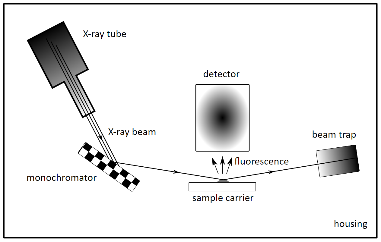
Figure 4Main components of the TXRF analysis setup. A polychromatic X-ray beam is monochromatized, impinges on the sample at a very flat angle, is totally reflected and ends in a beam trap; part of the X-ray radiation is absorbed in the sample and excites element-characteristic fluorescence, which is detected.
Handling of the sample carriers was carried out in a clean-room environment, especially after cleaning and during adhesive spin coating or photographic documentation. The transport of the sample carriers was carried out in a dust-proof magazine. To prevent contamination during the TXRF analysis, the spectrometer housing was continuously purged with air filtered through a HEPA H14 filter (TROX GmbH, Neukirchen-Vluyn, Germany).
4.1 Impactor blank values
Potential blank values due to material attrition are only to be expected for elements that the impactor is made of, which is mainly stainless steel essentially comprising the elements Fe, Cr and Ni. Elements such as lead, arsenic and cadmium are only to be found in neglectable traces. The element fluorine, which is present in the sealing rings (about 65 wt %), is not considered during analysis due to its low atomic number and the resulting methodological insensitivity of TXRF. Consequently, the main elements of stainless steel (Fe, Cr and Ni) are considered in the evaluation of possible blank values due to particle attrition of the impactor material.
Table 2Fe, Cr and Ni mean blank values of impactor stages 1–5 given in counts per 1000 s of the TXRF analysis and corresponding mass in nanograms, detected on the sample carriers after cleaning (TXRF no. 1), after performing assembly–disassembly five times (TXRF no. 2), after adhesive spin coating (TXRF no. 3) and after sampling with particle-free air for 5 min (TXRF no 4).
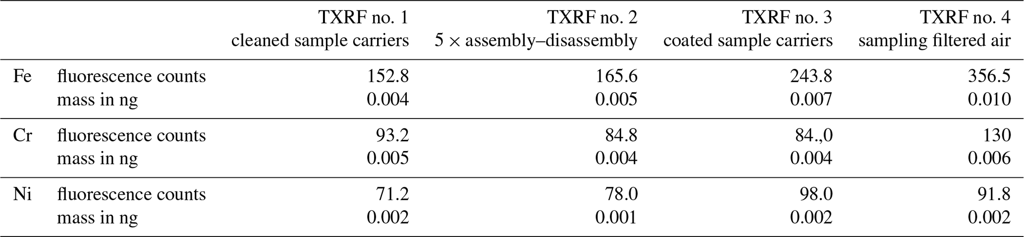
Table 2 shows the fluorescence intensity (counts) and the corresponding absolute mass of Fe, Cr and Ni as the mean values of impactor stages 1–5 determined by reviewing the sample carriers of the blank-value experiments. The mean values are calculated from five measurements. The maximal standard deviation was 0.0033 ng for Fe, 0.0016 ng for Cr and 0.0008 ng for Ni. With the TXRF spectrometer applied, absolute lower detection limits of 0.005 ng for Fe and Cr, as well as 0.002 ng for Ni, were achieved in realistic conditions utilizing the sample carriers from the blank value experiment. Over all impactor stages, the absolute masses determined are in the low picogram range and thus close to the absolute detection limit of the TXRF analysis.
With respect to Cr and Ni, 5 pg of Cr and 2 pg of Ni were detected for the cleaned sample carriers (TXRF analysis no. 1), and no significant increase was observed when assembling and disassembling the impactor five times (TXRF analysis no. 2), when coating the sample carriers with the adhesive (TXRF analysis no. 3), or when operating the impactor with filtered air (TXRF analysis no. 4). For Fe, the signal shows a slight tendency to increase from 4 to 10 pg over the course of the experiment, which, despite the clean-room environment, could be either due to an introduction of iron from the air or due to particles from impactor material attrition. In the case of particle attrition from the stainless-steel parts of the impactor, however, an increase in the nickel and chromium signal would be expected as well due to stainless steel forming a protective layer of chromium dioxide on its surface. Therefore, it is not clear whether the observed slight increase is due to particle attrition or due to particles of external origin. Since the sample carriers were transported through normal indoor air in dust-proof packaging during the experiment, it cannot be excluded that the slight increase in iron is due to contamination during this transport. It is noticeable that the increase in iron (3 pg) was highest in the sampling of filtered air. Despite the high-efficiency filtered air, there was possibly a small quantity of aerosol particles containing iron that passed through the high-efficiency filter and got collected within the impactor. Overall, the very small variations in the measured masses of Fe, Cr and Ni in these experiments show that potential impactor blank values caused by attrition or the coating of sample carrier are extremely low and close to the TXRF detection limit.
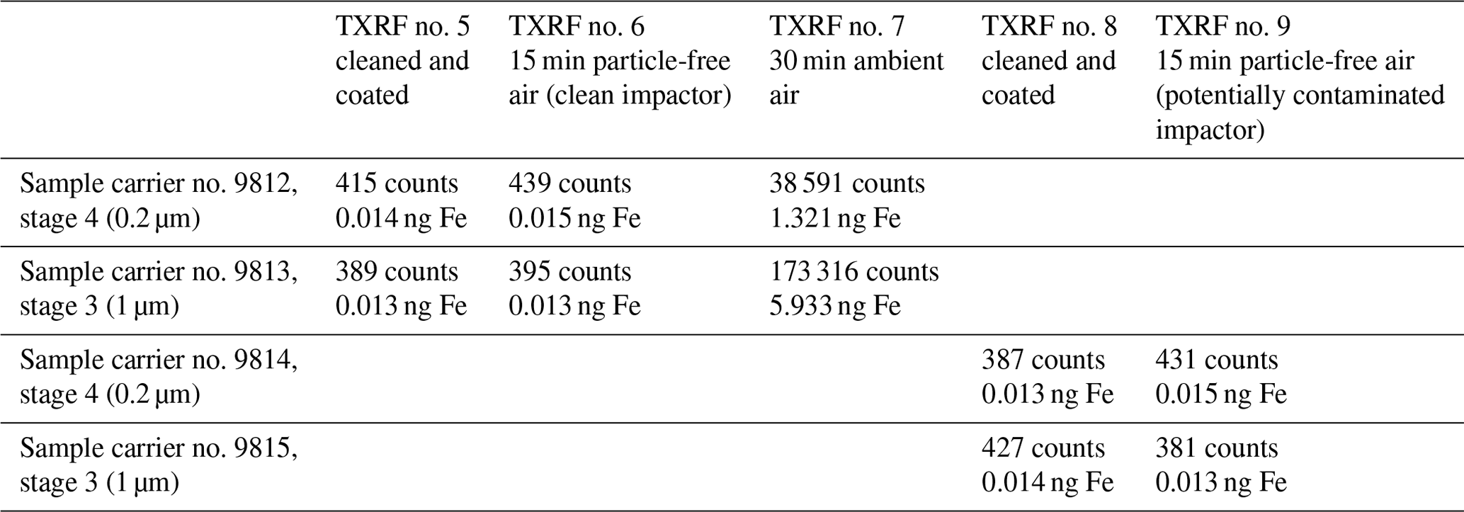
Table 3Fe masses observed in cross-contamination experiments; TXRF analyses no. 5 through no. 9.
4.2 Cross-contamination between subsequent sampling periods
Since iron seems to be a highly abundant heavy metal in atmospheric air relative to other heavy metals (Seeger et al., 2021), iron was chosen to be analysed to assess potential cross-contamination between subsequent sampling periods. In Table 3, the counts and the corresponding absolute masses of iron, which were determined during the cross-contamination experiments, are given. Photographs with perspective views of the four sample carriers can be found in Fig. S2.
A fluorescence intensity of approximately 400 counts was typically determined for iron on cleaned and coated sample carriers (TXRF no. 5). For example, with two cleaned and coated sample carriers (no. 9812 and no. 9813) installed in impactor stages 4 and 3, 415 counts and 389 counts, respectively, were determined. Considering the element-specific fluorescence sensitivity for iron, these counts correspond to an absolute mass of 0.014 and 0.013 ng, respectively. After installing these sample carriers into the impactor sampling filtered air for a 15 min period at 5 slpm, 439 counts and 395 counts were determined (TXRF no. 6). The very small increase of less than 24 counts and 6 counts, respectively, when sampling filtered air compared to cleaned sample carriers corresponds to a mass increase of less than 0.001 ng and is considered insignificant. Installing these sample carriers into the impactor again and collecting particles for 30 min at 5 slpm from ambient air, 38 591 counts (stage 4) and 173 316 counts (stage 3) were determined (TXRF no. 7). These counts correspond to an absolute mass of 1.321 and 5.933 ng of iron, respectively. Particle mass concentrations of 13.55 µg m−3 for the size fraction PM10, 8.93 µg m−3 for the size fraction PM2.5 and 7.16 µg m−3 for the size fraction PM1 were simultaneously determined by means of an optical aerosol spectrometer. Accordingly, the impactor was regarded as “potentially particle-contaminated” and was applied in this condition for the next experiment. Of two additional, cleaned and coated sample carriers (nos. 9814 and 9815), 387 counts and 427 counts (TXRF no. 8) were determined for iron. After mounting these sample carriers into the impactor and sampling filtered air for 15 min at 5 slpm, 431 counts and 381 counts of iron fluorescence photons were determined (TXRF no. 9). These very small variations of fewer than 50 counts resulting from the operation with a “potentially particle contaminated” impactor are considered to be insignificant and demonstrate that within the framework of these experiments cross-contamination is not observed for the impactor.
The masses of iron observed in the cross-contamination experiments are similar to but slightly larger than the blank value of 10 pg of iron found in TXRF analysis no. 4. However, both the absolute fluorescence intensity of approximately 400 counts and the variation between both experiments are 2 to 3 orders of magnitude smaller compared to the increase in fluorescence intensity when sampling ambient air for 30 min (TXRF analysis no. 7).
4.3 Particle collection in outdoor air
To investigate the impactor in a real-world application, particles were sampled in ambient air with the impactor optimized for TXRF analysis in the morning of 29 August 2022 at Potsdamer Platz, Berlin, Germany. Airborne particles were collected during three consecutive 30 min sampling periods from 08:00 to 08:30, 08:32 to 09:02 and 09:06 to 09:36. The bar chart in Fig. 5 shows the mass concentrations of the trace metals Zn, Cu, Mn, Pb and Ni collected during these three sampling periods in three size fractions, i.e. PM1 (the top of the blue bar, i.e. the sum of masses of impactor stages 4 and 5), PM2.5 (the top of the green bar, i.e. the sum of masses of impactor stages 3–5; the green bar represents the particle mass collected during stage 3 corresponding to PM2.5–PM1) and PM10 (the top of the red bar, i.e. the sum of masses of impactor stages 2–5; the red bar represents the particle mass collected during stage 2 corresponding to PM10–PM2.5). In addition, the pie charts give the corresponding PM10 concentrations estimated from Fidas Frog optical aerosol spectrometer measurements and the Fe mass fractions in PM10 (orange). The PM10 concentrations varied from 21.7 µg m−3 in the first 30 min sampling period to 27.9 µg m−3 in the second 30 min sampling period. The contribution of Fe to PM10 varied from 3.7 % (0.81 µg m−3) in the first period and 1.4 % (0.38 µg m−3) in the second period to 2.9 % (0.73 µg m−3) in the third period. Zn and Cu concentrations varied from 12.6 to 31.8 ng m−3 in PM10, and Mn, Pb and Ni concentrations were below 10 ng m−3 in PM10. Arsenic could not be detected in the samples. The observed 30 min concentrations of Pb in PM10 (ranging from 1.1 to 1.7 ng m−3) and Ni in PM10 (ranging from 0.4 to 0.6 ng m−3) are lower but consistent with the annual mean concentrations of Pb in PM10 (4.4 ng m−3 in 2021) and Ni in PM10 (0.6 ng m−3 in 2021) measured at the Berlin air quality network's (BLUME) station Berlin-Neukölln (Berliner Luftgütemessnetz, 2023). Detailed results of heavy metal concentrations in PM10, PM2.5 and PM1 can be found in Table S2. It should be kept in mind that the separation diameter of stage 5 is approximately 0.095 µm and that the particles with a smaller aerodynamic diameter were thus not fully captured in this impactor configuration. Although the mass contribution of these ultrafine particles can be considered very small (e.g. Seeger et al., 2021), additional nozzle modules with smaller separation diameters can be added to extend the lower size range of the impactor if required.
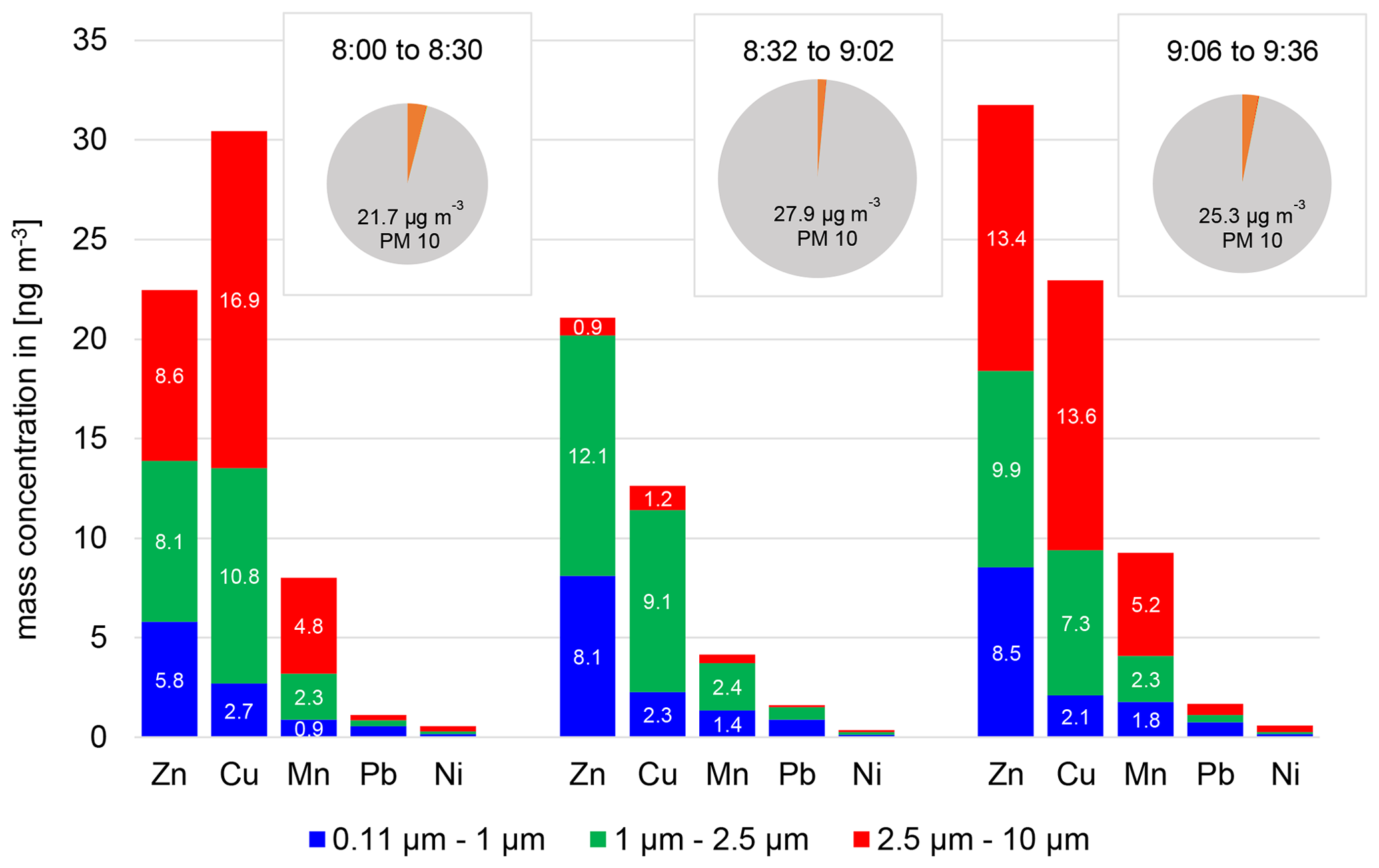
Figure 5Total PM10 (grey), Fe (orange), and trace metal concentrations (Zn, Cu, Mn, Pb, Ni) in three size fractions during three 30 min sampling periods on 29 August 2022 at Potsdamer Platz, Berlin, Germany.
In the present case study, it is interesting to note that considerable concentrations of trace metals can be found in the PM2.5 fraction and even in the PM1 fraction (especially Zn and Pb). In the second sampling period (Fig. 5b), the concentrations of Fe and other trace metals in the coarse mode from 2.5 to 10 µm are much lower than in the first and third sampling period. This indicates a transient change in the chemical composition of coarse-mode particles, while variations in the fine fraction are less pronounced. Such short-term variations, possibly due to variable source strength patterns, can only be observed with measurements of sufficiently high time resolution. It is evident from Fig. 5 that with the optimized impactor and the high sensitivity of TXRF analysis, 30 min sampling times are sufficient to reliably quantify trace metal concentrations including lead and nickel in size fractions of PM10, PM2.5 and PM1 in moderate atmospheric concentrations.
The newly developed impactor optimized for TXRF analysis opens new perspectives in the determination and quantification of particulate trace metals and other elements with high time resolution. Due to the compact arrangement of the impactor nozzles, the entire sample interacts with the TXRF excitation beam and contributes to the TXRF analysis signal, thereby supporting the high detection sensitivity of the TXRF analysis method. We demonstrate that a large number of different heavy metals can be detected and quantified in the PM10, PM2.5 and PM1 size fractions after collection periods of 30 min. Thus, snapshot sampling with collection periods of significantly less than 1 h is possible. Sampling carriers can be exchanged in less than 5 min including the disassembly and assembly of the impactor stages, and the total procedure from sampling with the impactor to the result of the TXRF elemental analysis takes only a few hours. This offers new possibilities for the identification of pollutant sources and the evaluation of protective measures. The flow rate required for sampling is relatively low at 5 slpm, which means that the associated pump can be operated with a portable rechargeable energy source. This enables flexible, mobile sample collection, even in public spaces with a high volume of people or traffic. Blank values and cross-contamination potential as previously reported for stainless-steel impactors were not detected by the new impactor, even with the low detection limits of TXRF analysis. Furthermore, the new spin-coating method provides adhesive coating of the sample carriers with very low surface roughness, which is advantageous for TXRF analysis.
A characterization of the separation efficiency of individual impactor stages is currently in preparation. Calibration of the classification diameters and efficiency curves of individual impactor stages is possible through an adjusted design of the impactor nozzle arrangements in the exchangeable nozzle modules. A reduced nozzle diameter and an increased number of nozzles, for example by laser drilling, would reduce the differential pressure across the nozzle stage and facilitate the addition of impactor stages with smaller separation diameters. Care should be taken to adjust the sampling time according to the expected atmospheric particle burden. Overloading of the sample carriers with particles will lead to self-absorption of fluorescence radiation within the sample matrix. In this case, applying a linear relationship between fluorescence intensity and element mass concentration will underestimate the actual concentration. Further improvement of the quantitative TXRF analysis is possible with approaches such as grazing incidence X-ray fluorescence (e.g. Hönicke et al., 2020), where variation in the incident angle of the excitation beam yields fluorescence from different parts of the deposited sample.
The software used to evaluate the results of the TXRF analysis (Bruker ESPRIT, as mentioned in Sect. 3.3) is available at https://www.bruker.com/de/products-and-solutions/elemental-analyzers/eds-wds-ebsd-SEM-Micro-XRF/software-esprit-family.html (Bruker Nano GmbH, 2024).
The datasets used and/or analyzed during the current study are available from the corresponding author upon reasonable request (crazzolara@tu-berlin.de).
The supplement related to this article is available online at: https://doi.org/10.5194/amt-17-2183-2024-supplement.
Formal analysis, investigation, methodology, visualization and writing (original draft preparation) were performed by CC. Conceptualization, validation and writing (review and editing) were performed by CC and AH.
The contact author has declared that neither of the authors has any competing interests.
Publisher's note: Copernicus Publications remains neutral with regard to jurisdictional claims made in the text, published maps, institutional affiliations, or any other geographical representation in this paper. While Copernicus Publications makes every effort to include appropriate place names, the final responsibility lies with the authors.
The authors are grateful for funding from Bruker Nano GmbH and additional technical support from the Bruker Nano staff. We acknowledge support by the Open Access Publication Fund of TU Berlin.
This study was financially supported by Bruker Nano GmbH.
This open-access publication was funded by Technische Universität Berlin.
This paper was edited by Mingjin Tang and reviewed by Weijun Li and two anonymous referees.
Allen, M. D. and Raabe, O. G.: Re-evaluation of Millikan's oil drop data for the motion of small particles in air, J. Aerosol Sci., 13, 537–547, 1982.
Allen, M. D. and Raabe, O. G.: Slip correction measurements of spherical solid aerosol particles in an improved Millikan apparatus, Aerosol Sci. Tech., 4, 269–286, 1985.
Beckhoff, B., Fliegauf, R., Kolbe, M., Müller, M., Weser, J., and Ulm, G.: Reference-free total reflection X-ray fluorescence analysis of semiconductor surfaces with synchrotron radiation, Anal. Chem., 79, 7873–7882, 2007.
Berliner Luftgütemessnetz: Jahresbericht 2021, Senatsverwaltung für Umwelt, Mobilität, Verbraucher- und Klimaschutz, Berliner Luftgütemessnetz, Berlin, Germany, https://www.berlin.de/sen/ uvk/_assets/umwelt/luft/luftqualitaet/luftdaten-archiv/monats-und-jahresberichte/jahresbericht2021.pdf (last access: 1 August 2023), 2023.
Bruker Nano GmbH: Software: ESPRIT Familie, https://www.bruker.com/de/products-and-solutions/elemental-analyzers/eds-wds-ebsd-SEM-Micro-XRF/software-esprit-family.html, last access: 5 April 2024.
CEN: Ambient air quality – Standard method for the measurement of Pb, Cd, As and Ni in the PM10 fraction of suspended particulate matter, European Committee for Standardization, EN 14902:2005, Beuth Verlag Gmbh, Berlin, Germany, 2005.
Chen, J. and Hoek, G.: Long-term exposure to PM and all-cause and cause-specific mortality: a systematic review and meta-analysis, Environ. Int., 143, 105974, https://doi.org/10.1016/j.envint.2020.105974, 2020.
Corriveau, M. C., Jamieson, H. E., Parsons, M. B., Campbell, J. L., and Lanzirotti, A.: Direct characterization of airborne particles associated with arsenic-rich mine tailings: Particle size, mineralogy and texture, Appl. Geochem., 26, 1639–1648, 2011.
Eichert, D.: The Fundamentals of Total Reflection X-ray Fluorescence, Spectroscopy, 35, 20–24, 2020.
European Parliament: Directive 2004/107/EC of the European Parliament and of the Council of 15 December 2004 relating to arsenic, cadmium, mercury, nickel and polycyclic aromatic hydrocarbons in ambient air, Publications Office of the European Union, EUR-Lex & Legal Information Unit, Luxembourg, http://data.europa.eu/eli/dir/2004/107/oj (last access: 1 August 2023), 2004.
European Parliament: Directive 2008/50/EC of the European Parliament and of the Council of 21 May 2008 on ambient air quality and cleaner air for Europe, Publications Office of the European Union, EUR-Lex & Legal Information Unit, Luxembourg, http://data.europa.eu/eli/dir/2008/50/oj (last access: 1 August 2023), 2008.
Fang, C. P., Marple, V. A., and Rubow, K. L.: Influence of cross-flow on particle collection characteristics of multi-nozzle impactors, J. Aerosol Sci., 22, 403–415, 1991.
Feng, S., Gao, D., Liao, F., Zhou, F., and Wang, X.: The health effects of ambient PM2.5 and potential mechanisms, Ecotox. Environ. Safe., 128, 67–74, 2016.
Fuzzi, S., Baltensperger, U., Carslaw, K., Decesari, S., Denier van der Gon, H., Facchini, M. C., Fowler, D., Koren, I., Langford, B., Lohmann, U., Nemitz, E., Pandis, S., Riipinen, I., Rudich, Y., Schaap, M., Slowik, J. G., Spracklen, D. V., Vignati, E., Wild, M., Williams, M., and Gilardoni, S.: Particulate matter, air quality and climate: lessons learned and future needs, Atmos. Chem. Phys., 15, 8217–8299, https://doi.org/10.5194/acp-15-8217-2015, 2015.
García-Ruiz, E., Romay, F. J., García, J. A., Cambra, J. F., Alonso, L., and Legarreta, J. A.: Effect of nozzle spacing in the formation of primary and secondary deposits in multi-nozzle inertial impactors part I: Experimental study, J. Aerosol Sci., 136, 61–81, 2019a.
García-Ruiz, E., Romay, F. J., García, J. A., Iza, J. M., Cambra, J. F., Gangoiti, G., and Legarreta, J. A.: Effect of nozzle spacing in the formation of primary and secondary deposits in multi-nozzle inertial impactors part II: Numerical study, J. Aerosol Sci., 136, 106–127, 2019b.
Gietl, J. K., Lawrence, R., Thorpe, A. J., and Harrison, R. M.: Identification of brake wear particles and derivation of a quantitative tracer for brake dust at a major road, Atmos. Environ., 44, 141–146, 2010.
Hillamo, R. E. and Kauppinen, E. I.: On the performance of the Berner low pressure impactor, Aerosol Sci. Tech., 14, 33–47, 1991.
Hönicke, P., Andrle, A., Kayser, Y., Nikoaev, K. V., Probst, J., Scholze, F., Soltwisch, V., Weimann, T., and Beckhoff, B.: Grazing incidence-x-ray fluorescence for a dimensional and compositional characterization of well-ordered 2D and 3D nanostructures, Nanotechnology, 31, 505709, https://doi.org/10.1088/1361-6528/abb557, 2020.
Injuk, J. and Van Grieken, R.: Optimisation of total-reflection X-ray fluorescence for aerosol analysis, Spectrochim. Acta B, 50, 1787–1803, 1995.
Klockenkämper, R., Bayer, H., von Bohlen, A., Schmeling, M., and Klockow, D.: Collection of airborne particulate matter for a subsequent analysis by total reflection X-ray fluorescence, Anal. Sci., 11, 495–498, 1995.
Kuhn, T., Biswas, S., Fine, P. M., Geller, M., and Sioutas, C.: Physical and chemical characteristics and volatility of PM in the proximity of a light-duty vehicle freeway, Aerosol Sci. Tech., 39, 347–357, 2005.
Marple, V. A.: History of impactors – the first 110 years, Aerosol Sci. Tech., 38, 247–292, 2004.
Marple, V. A. and Willeke, K.: Impactor design, Atmos. Environ., 10, 891–896, 1976.
Marple, V. A., Rubow, K. L., and Behm, S. M.: A microorifice uniform deposit impactor (MOUDI): Description, calibration, and use, Aerosol Sci. Tech., 14, 434–446, 1991.
Rader, D. J. and Marple, V. A.: Effect of ultra-Stokesian drag and particle interception on impaction characteristics, Aerosol Sci. Tech., 4, 141–156, 1985.
Prost, J., Wobrauschek, P., and Streli, C.: Quantitative total reflection X-ray fluorescence analysis of directly collected aerosol samples, X-Ray Spectrom., 46, 454–460, 2017.
Schneider, B.: The determination of atmospheric trace metal concentrations by collection of aerosol particles on sample holders for total-reflection X-ray fluorescence, Spectrochim. Acta B, 44, 519–523, 1989.
Seeger, S., Osan, J., Czömpöly, O., Gross, A., Stosnach, H., Stabile, L., Ochsenkuehn-Petropoulou, M., Tsakanika L. A., Lymperopoulou T., Goddard, S., Fiebig M., Gaie-Levrel F., Kayser Y., and Beckhoff, B.: Quantification of element mass concentrations in ambient aerosols by combination of cascade impactor sampling and mobile total reflection X-ray fluorescence spectroscopy, Atmosphere, 12, 309, https://doi.org/10.3390/atmos12030309, 2021.
Streli, C.: Recent Advances in TXRF, Appl. Spectrosc. Rev., 41, 473–489, https://doi.org/10.1080/10543400600809318, 2006.
Streli, C., Wobrauschek, P., Meirer, F., and Pepponi, G.: Synchrotron radiation induced TXRF, J. Anal. Atom. Spectrom., 23, 792–798, 2008.
WHO: WHO global air quality guidelines: particulate matter (PM2.5 and PM10), ozone, nitrogen dioxide, sulfur dioxide and carbon monoxide, World Health Organization, Geneva, Switzerland, https://apps.who.int/iris/handle/10665/345329 (last access: 1 August 2023), 2021.
Yoneda, Y. and Horiuchi, T.: Optical flats for use in X-ray spectrochemical microanalysis, Rev. Sci. Instrum., 42, 1069–1070, 1971.