the Creative Commons Attribution 4.0 License.
the Creative Commons Attribution 4.0 License.
 | 08 May 2024
Characterization of the airborne aerosol inlet and transport system used during the A-LIFE aircraft field experiment
Manuel Schöberl
Maximilian Dollner
Josef Gasteiger
Petra Seibert
Anne Tipka
Bernadett Weinzierl
Atmospheric aerosol particles have a profound impact on Earth's climate by scattering and absorbing solar and terrestrial radiation and by impacting the properties of clouds. Research aircraft such as the Deutsches Zentrum für Luft- und Raumfahrt e.V. (DLR) Falcon are widely used to study aerosol particles in the troposphere and lower stratosphere. However, transporting a representative sample to the instrumentation inside the aircraft remains a challenge due to high airspeeds and changing ambient conditions. In particular, for high-quality coarse-mode aerosol measurements, knowledge about losses or enhancements in the aerosol sampling system is crucial. In this study, the sampling efficiency of the aerosol inlet aboard the Falcon research aircraft is characterized for the first time with state-of-the art in situ measurements including sizing instruments operated behind the Falcon aerosol inlet and mounted at the aircraft wing not affected by the aerosol inlet. Sampling efficiencies were derived for different true airspeed ranges by comparing the in-cabin and ”full”-size-range particle number size distributions during 174 flight sequences with a major contribution of mineral dust particles during the ”Absorbing aerosol layers in a changing climate: aging, lifetime and dynamics” project (A-LIFE). Additionally, experimentally derived Stokes numbers were used to calculate the cutoff diameter of the aerosol sampling system for different particle densities as a function of true airspeed. As expected, the results show that the velocity of the research aircraft has a major impact on the sampling of coarse-mode aerosol particles with in-cabin instruments. For true airspeeds up to about 190 m s−1, aerosol particles larger than about 1 µm are depleted in the sampling system of the Falcon during the A-LIFE project. In contrast, for true airspeeds higher than 190 m s−1, an enhancement of particles up to a diameter of 4 µm is observed. For even larger particles, the enhancement effect at the inlet is still present, but inertial and gravitational particle losses in the transport system get more and more pronounced, which leads to a decreasing overall sampling efficiency. In summary, aerosol particles are either depleted or enhanced in the Falcon aerosol inlet, whereas transport in sampling lines always leads to a loss of particles. Here, we have considered both effects and determined the cutoff diameter for the A-LIFE transport system (i.e., the sampling lines only), the cutoff diameter of the Falcon aerosol inlet (i.e., the effect of the inlet only), and the combined effect of the inlet and sampling lines.
- Article
(3596 KB) - Full-text XML
-
Supplement
(731 KB) - BibTeX
- EndNote


Atmospheric aerosol particles play an important role in the changing climate system. Due to their ability to scatter and absorb solar and terrestrial radiation, as well as their impact on cloud properties, they can influence Earth's climate (Boucher et al., 2013). In recent years, there has been an increasing interest in studying aerosol particles directly in the atmosphere with an aircraft equipped with aerosol instruments installed in the aircraft cabin, under the aircraft wings, or at the fuselage (e.g., Wendisch and Brenguier, 2013; Weinzierl et al., 2017, 2024). Crucial for the in-cabin instrumentation is the sampling system (consisting of inlets and sampling lines) aboard the aircraft which transports the ambient aerosol particles to the instruments. One of the greatest challenges of airborne measurements is to design and operate the sampling system such that biases in the measurements of aerosol properties are avoided despite facing different ambient conditions (e.g., varying true airspeed of the aircraft, changing temperature, and pressure; Baumgardner and Huebert, 1993; Wendisch et al., 2004). In particular, coarse-mode aerosol particles (particle diameter > 1 µm)1 are affected by sampling effects due to their high inertia, which can result in an artificial depletion or enhancement (Hinds, 1999; Brockmann, 2011). Hence, a characterization of the sampling system2 aboard any research aircraft is imperative.
An efficiency η defines the change in particle number concentration before and after a certain part of the sampling system as a function of particle diameter Dp. In cases where there is a sampling system aboard a research aircraft, changes in particle number concentration can occur at the sampling system inlet and in the transport system. While the inlet efficiency describes particle losses (ηin<1) or enhancements (ηin>1) at the sampling system inlet, the transport efficiency ηtr defines the particle depletion due to different loss mechanisms (e.g., gravitational settling, losses in bends) in the sampling lines, which connect the instrument with the inlet. In addition to the particle size, these efficiencies depend on various parameters including particle density, sampling system geometry (e.g., the inlet design, the number of bends in the transport system, the bend angle, and the horizontal or vertical sampling lines), and flow velocity (Hinds, 1999; Brockmann, 2011). Hence, a sampling system can be characterized by the overall sampling efficiency ηsys which is given by multiplying the inlet efficiency ηin and the transport efficiency ηtr (Brockmann, 2011) as follows:
A key aspect of the inlet efficiency is the ratio between the ambient air velocity U0 and the stream velocity inside the inlet U (Brockmann, 2011; Belyeav and Levin, 1972, 1974). A representative sample of ambient aerosol particles enters the inlet if the ratio equals unity and the inlet is aligned in parallel to the flow direction. Sampling with is known as isokinetic sampling. For conditions with U<U0, the sampling is called sub-isokinetic sampling: the ambient air streamlines diverge at the inlet entry, and particles with high inertia cannot follow the streamlines and are artificially enriched in the sampling system inlet. Super-isokinetic sampling is given for the opposite case (U>U0) where the ambient air streamlines converge into the inlet. Thus, particles with high inertia are underrepresented in the sampling probe. Belyeav and Levin (1972, 1974) derived an empirical formula to determine the aspiration efficiency for aerosol inlet systems. The formula was derived for inlet nozzles operated under different ratios between ambient air velocity U0 and the air velocity in the inlet tube U (). The formula is valid for thin-walled inlet nozzles with a ratio of external to internal diameter of less than 1.1 (see also Brockmann, 2011). However, aerosol inlets on aircraft have a typically more complex geometry, such as including diffusers to slow down the airflow and bends. Furthermore, a number of other additional sampling effects can influence the inlet efficiency (see Sect. 2.2.1). Hence, a characterization of the inlet and sampling system in general aboard a research aircraft is imperative.
Many research aircraft, such as the DLR Falcon or the NASA DC-8, move with , which is typically greater than the stream velocity at the inlet entry (typically defined by the total volume flow needed by the in-cabin instrumentation). Nearly isokinetic sampling conditions can be accomplished by a diffuser which decelerates the ambient air before entering the sampling system (Seebaugh, 1991). Numerous studies investigated the sampling efficiency of such diffuser-type aerosol inlets with different approaches: for example, several airborne aerosol inlets (e.g., aboard the NASA DC-8 research aircraft) were characterized experimentally by in-flight testing or comparisons of instrument data (Huebert et al., 1990; Porter et al., 1992; Sheridan and Norton, 1998; McNaughton et al., 2007). Hermann et al. (2001) conducted wind-tunnel tests to characterize the aerosol inlet installed on a Boeing civil aircraft. A similar approach is described in Hegg et al. (2005) to determine the inlet's transmission efficiency of the CIRPAS (Center for Interdisciplinary Remotely Piloted Aircraft Studies) Twin Otter research aircraft. Wilson et al. (2004) showed that coarse-mode aerosol particles are enhanced in the sample flow and that the enhancement factor can be described as a function of the Stokes number. A more theoretical approach for various inlets is demonstrated in Krämer and Afchine (2004) by comparing empirically derived equations from Belyaev and Levin (1972, 1974) to computational fluid dynamics (CFD) model results. In general, inlet systems are constantly being improved and renewed for different aircraft campaigns; for example, this is done in order to measure aerosol particles only in a certain size range (Dhaniyala et al., 2003; Perring et al., 2013).
Here, we carry out a comprehensive characterization of the sampling system of the Falcon, which was used as the research aircraft during the A-LIFE field campaign (Weinzierl et al., 2024) and has been used for many aircraft missions in the past decades (e.g., SALTRACE, Weinzierl et al., 2017; ACCESS, Moore et al., 2017). Fiebig (2001) investigated the Falcon aerosol inlet's cutoff diameter Dp,50 (particle diameter at which the overall sampling efficiency equals 50 %) as a function of flight altitude during the Lindenberger Aerosol Characterization Experiment 1998 (LACE 98; Ansmann et al., 2002), but the analysis was restricted to six flight sequences within the planetary boundary layer. In this study, we use the entire data set of the A-LIFE mission for the characterization which covers the entire altitude range of the Falcon from the ground to about 12 km.
This paper is structured as follows. Section 2 gives an overview of the A-LIFE aircraft field campaign, introduces the Falcon aerosol inlet and the A-LIFE aerosol transport system, and summarizes the derived aerosol number size distributions. Furthermore, the methodology of the sampling system characterization is explained. The results are described in Sect. 3 and contain the following key outcomes: classification of each A-LIFE flight sequence according to the sampling condition, cutoff diameters Dp,50 of the Falcon sampling system for a number of particle densities between 1.0 and 2.6 g cm−3, and sampling efficiencies derived for different ranges of ambient air velocities U0. The last two sections of this paper include the discussion of the results and the conclusion of this study.
2.1 A-LIFE field campaign
The European Research Council (ERC) project “Absorbing aerosol layers in a changing climate: aging, lifetime and dynamics” (A-LIFE) conducted ground-based and airborne measurements to characterize mixtures of absorbing aerosol particles (in particular mineral dust and black carbon) in the atmosphere. For A-LIFE, the DLR Falcon 20-E5 D-CMET research aircraft (hereafter simply referred to as Falcon) was used for the airborne measurements in spring 2017. During this time, the aircraft was based in Paphos, Cyprus, and it provided access to dust layers originating from the Sahara or the Arabian Peninsula and to polluted aerosol layers (Weinzierl et al., 2024).
In total, 22 research flights were conducted (including 4 transfer flights and 2 test flights) with a total number of about 80 flight hours. For A-LIFE, a substantial number of aerosol instruments, a wind lidar, and impactors for a subsequent analysis of filter samples were installed on the Falcon research aircraft. The resulting unique data set includes measurements of particle number size distribution in the size range of 10 nm up to 930 µm, aerosol optical properties, cloud condensation nuclei (CCN), and refractory black carbon (rBC) mass and mixing states. Additionally, a Rosemount five-hole pressure probe model 858 was installed on the tip of the aircraft for meteorological measurements (hereafter referred to as the CMET system according to the aircraft's call sign D-CMET; Bögel and Baumann, 1991). In order to define averaging time periods, the research flights were divided into flight sequences in which the Falcon flew at a constant altitude in quasi-homogeneous aerosol concentrations. Periods in which the Falcon flew in clouds were not considered, since cloud particles can produce artifacts at the inlet and thus artificially increase the number concentration (Murphy et al., 2004). The algorithm used for the detection of clouds is described by Dollner (2022) and Dollner et al. (2023). Altogether, the A-LIFE data set was divided into 262 flight sequences.
To enable a consistent statistical analysis of the A-LIFE data set, an aerosol classification of all flight sequences was established. It was derived by considering in situ measurements of coarse-mode aerosol particles and refractory black carbon mass in combination with the Lagrangian particle dispersion model FLEXPART (Stohl et al., 1998; Seibert and Frank, 2004). The model is driven by meteorological data from the European Centre for Medium-Range Weather Forecasts (ECMWF) and, in combination with emission data from the Copernicus Atmosphere Monitoring Service (CAMS), provides quantitative information about the types of the measured aerosol and their origins. The aerosol classification scheme for A-LIFE (Weinzierl et al., 2024) divides the data set into flight sequences with (174) and without (88) a primary contribution of mineral dust in the coarse-mode size range (particle diameter > 1 µm). Further distinctions are made based on the degree of pollution (polluted, moderately polluted, pure) and the source region of mineral dust particles (Saharan and Arabian dust). For this study, mainly sequences with a mineral dust contribution (hereafter abbreviated to dust sequences) are considered. Details about the A-LIFE aerosol classification can be found in Weinzierl et al. (2024).
2.2 Falcon aerosol inlet and A-LIFE aerosol transport system
An aerosol sampling system consists of an inlet and a sampling line system connecting the inlet with the individual instruments. As outlined in Eq. (1), the overall sampling efficiency ηsys is given as the product of the inlet efficiency ηin and the transport efficiency ηtr.
The Falcon aerosol inlet system, which was designed by Franz Schröder (formerly DLR), is depicted in Fig. 1 and consists of four different inlets: the diffuser and isokinetic inlet3, the forward-facing inlet, the sideward inlet (not visible in Fig. 1), and the backward-facing inlet (Fiebig, 2001; Schneider et al., 2006). The majority of in-cabin instruments was connected to the isokinetic aerosol inlet. Therefore, we restrict this study to the isokinetic inlet of the Falcon and do not further investigate the forward-facing, sideward, and backward-facing inlet. The flow plan for the aerosol transport system, which was installed and used during the A-LIFE campaign, can be seen as a schematic in Fig. S2 in the Supplement.
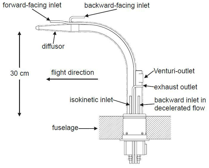
Figure 1Schematic of the Falcon aerosol inlet adapted from Fiebig (2001). The inlet was constructed by Franz Schröder (formerly DLR). The majority of the A-LIFE instrumentation was connected to the isokinetic inlet. In the diffuser, the ambient airstream velocity is reduced by a factor of 7.1. Figure reprinted from Fiebig (2001) with permission of Markus Fiebig, NILU.
2.2.1 Inlet system
Before the sample air reaches the isokinetic inlet, it passes through a blunt-edged diffuser in which the ambient air velocity U0 is decelerated. The diffuser, which has the shape of a cone with an opening angle of 2θ=6.3°, is mounted with a distance of 30 cm to the aircraft's fuselage in order to be outside of the boundary layer of the aircraft (Fiebig, 2001). During the 174 flight sequences with a major contribution of mineral dust, the angle of attack of the aircraft varied on average by 0.7° over the whole operation range of the Falcon between the ground and ∼12 km altitude and is therefore no longer considered in the analysis of the inlet efficiency in this study. The deceleration of the ambient air is determined by the ratio of the cross-sectional areas at the end and at the beginning of the diffuser, which equals 7.1 in the case of the Falcon inlet. Furthermore, the sample air is transported through a bend of 90° with a radius of 19 cm, leading to the isokinetic inlet mounted perpendicular to the aircraft's fuselage (see Fig. 1). The isokinetic inlet has an inner diameter of 4.572 mm and connects the inlet system to the sampling line system transporting the aerosol particles to the individual instruments (see Fig. S2). In total, the A-LIFE in-cabin instrumentation needed a volumetric flow between 17.87 and 22.83 L min−1 at the isokinetic inlet (18.14–23.18 m s−1 when considering the inlet's inner diameter). Since during the A-LIFE campaign the inlet flow was not controlled with a bypass only in a certain range of ambient air velocity isokinetic sampling conditions were established. Inside the isokinetic sampling tube (approximately 35 cm long), the flow Reynolds number shows values larger than 2000 for the whole operation range of the Falcon, which indicates that the flow was never laminar in this tubing piece (see Fig. S1). Note that the inlet efficiency ηin presented in this study is derived from experimentally determined sampling efficiencies and theoretically calculated transport efficiencies (see Sect. 2.3.2). The resulting efficiencies refer to the whole inlet system which contains all components shown in Fig. 1 (diffuser, the tube with the 90° bend, and the isokinetic inlet tube) and covers a number of different sampling effects (e.g., compressional heating, turbulence due to the blunt-edge design of the inlet system, and turbulence in the isokinetic inlet tube).
As a measure of the ambient air velocity U0, the true airspeed (hereafter abbreviated to vTAS) is used. The vTAS is the velocity of the aircraft with respect to the surrounding air mass. The measurement of vTAS was provided by the CMET system. In Fig. 2, a 2D histogram of the recorded vTAS during the A-LIFE campaign is depicted as a function of altitude, and it is color-coded with the number of seconds spent in these conditions. The vTAS ranges roughly from 70 m s−1 at ground level to 220 m s−1 for altitudes up to nearly 12 km. With a flow velocity of 18.14–23.18 m s−1 inside the isokinetic inlet and a deceleration of the ambient air velocity by a factor of 7.1, isokinetic sampling conditions at the isokinetic inlet are established with a vTAS of approximately 129–165 m s−1.

Figure 2Two-dimensional histogram of true airspeed values vTAS recorded by the CMET nose boom of the Falcon research aircraft as a function of altitude for every flight second during the A-LIFE mission.
2.2.2 A-LIFE aerosol transport system
Sampling lines with a diameter of in. (6.35 mm) connected the isokinetic inlet with the in-cabin instrumentation and constituted the transport system aboard the Falcon. An overview of the instrumentation and the sampling line lengths is given in the Supplement (Fig. S2 and Table S1). Estimations of the transport efficiency ηtr of coarse-mode aerosol particles were computed considering sedimentation and bend losses with empirical equations from literature (see Thomas, 1958; Fuchs, 1964; Pui et al., 1987). For these calculations, 4.572 mm was taken as the inner diameter of the sampling lines due to a wall thickness of 0.889 mm. For details of the calculations, see the Supplement. The transport efficiency for different instruments can vary due to the various sampling line lengths. In general, longer sampling lines lead to more losses of aerosol particles in the coarse-mode size range.
2.3 Aerosol number size distribution
For the A-LIFE field experiment for each of the 262 flight sequences at a constant altitude, a log-normal fitted aerosol number size distribution (NSD) was derived (Weinzierl et al., 2024). The measurements from two optical particle counters (OPCs), namely the Ultra High Sensitivity Aerosol Spectrometer-Airborne (UHSAS-A) from the manufacturer Droplet Measurement Technologies (DMT; Longmont, CO, USA) and the in-cabin SkyOPC (model 1.129; GRIMM Aerosol Technik; Ainring, Germany) were combined into an in-cabin NSD (nin). For the NSDs, which represent the full particle size range (nfull), measurements of the UHSAS-A and the SkyOPC were combined with coarse-mode size distribution measurements of a wing-mounted DMT Second Generation Cloud, Aerosol, and Precipitation Spectrometer (UNIVIE CAPS; Dollner, 2022; Dollner et al., 2023; Spanu et al., 2020), which is not affected by sampling losses due to the Falcon aerosol inlet. Table S2 in the Supplement summarizes the instruments used for the two sets of NSDs.
In order to derive a NSD from OPC measurements, which represents geometric particle diameters (instead of optical-equivalent diameters), the choice of the aerosol-type-dependent refractive index and, hence, the scattering cross-section to particle diameter relationship is critical (Rosenberg et al., 2012; Walser et al., 2017). For the A-LIFE NSDs, the refractive indices were inferred from the aerosol composition determined by the FLEXPART model. Both sets of NSDs were fitted with log-normal functions which were restricted by the integral particle number concentration measured by the TSI 3760a condensation particle counter (CPC2; TSI Inc.; Aachen, Germany). For the calculation of the NSDs, a Monte Carlo method was applied to cover aerosol-specific uncertainties (e.g., scattering cross-section function) as well as instrumental (e.g., calibration, spectral broadening) uncertainties. Therefore, for each flight sequence, 1000 NSDs were derived with randomly selected input parameters. For this study, the comparison of the in-cabin and full-size-range aerosol number size distribution (nin and nfull) plays a fundamental role in quantifying losses and enhancements of aerosol particles due to the sampling system.
2.4 Sampling system characterization
The characterization of the aerosol sampling system aboard the Falcon aircraft during the A-LIFE field campaign consists of three parts. First, each of the 262 flight sequences was assigned to one of three groups with respect to the sampling conditions: “depletion” (), “representative sample” (), or “enrichment” () of coarse-mode aerosol particles in the in-cabin NSD compared to the full-size-range NSD. Second, the sampling efficiencies during measurement periods inside mineral dust layers (“dust sequences”) were derived by comparing the in-cabin to full NSD. As stated earlier, the sampling efficiency is affected by both inlet and transport losses. Therefore, the inlet efficiency was derived by dividing the experimentally determined sampling efficiency by the transport efficiency calculated based on equations from literature (see the Supplement). Third, the cutoff diameters were derived from the sampling efficiencies as a function of vTAS and calculated for different particle densities. In the next paragraphs, each of the three steps is described in more detail.
2.4.1 Sampling condition classification
For the classification of the sampling conditions, the log-normal fitted in-cabin and full NSDs were integrated into the size range from 1 to 10 µm. The resulting particle number concentrations inside the aircraft cabin (Nin) and from the full size range (Nfull) were used for the derivation of the classification criteria. If the difference between Nin and Nfull normalized by Nfull is between −0.1 and 0.1 (i.e., ±10 %), the measured in-cabin aerosol sample during a specific flight sequence is considered to be a representative sample of the ambient aerosol.
Cases with are designated as depletion. In contrast, cases with are labeled as enrichment. The classification criteria are summarized in Table 1. Figure 3 shows examples for each of the three classes at three different true airspeeds vTAS. In the case of particle depletion (Fig. 3a) and particle enrichment (Fig. 3c), the in-cabin and full NSDs deviate from each other for particle sizes above ∼1 µm. For the representative sample (Fig. 3b) observed at , nin and nfull are in agreement within the NSD uncertainties.
Table 1Criteria for classifying each flight sequence in relation to the current sampling condition.
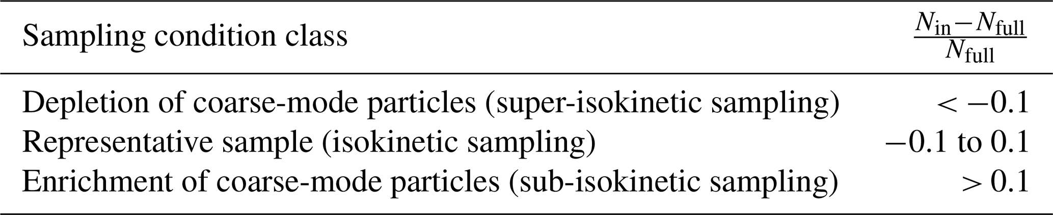
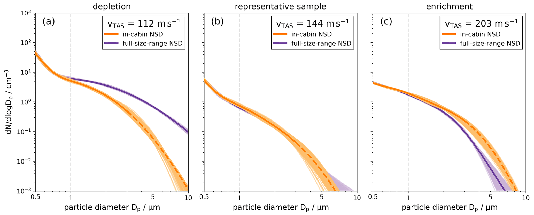
Figure 3Examples of in-cabin (orange) and full-size-range (violet) aerosol number size distributions (NSDs) during flight sequences with a major contribution of mineral dust particles in the coarse-mode size range. For each color, the darker line represents the mean NSDs derived from the aerosol-type-dependent refractive index ensemble. For particles larger than 3 µm, the in-cabin mean NSD is shown by dashed lines to indicate that for particles > 3 µm, the in-cabin NSD is only based on the log-normal fits. The lighter-colored range indicates the NSD uncertainty. Panels (a)–(c) show examples of the three different sampling conditions: (a) a case with depletion of particles larger than 1 µm, (b) a case in which the in-cabin instrumentation is representative of the ambient aerosol, and (c) a case of enrichment of coarse-mode particles due to sampling effects caused by the inlet system. Note that the corresponding vTAS values are different for all three sampling condition cases. We want to emphasize that the ratio of the velocities is decisive whether depletion, representative sampling, or enrichment occurs.
2.4.2 Sampling, transport, and Falcon inlet efficiency
For the derivation of the sampling efficiency ηsys, the experimentally observed NSDs during the 174 mineral dust flight sequences were grouped into four sets according to the vTAS during the flight sequence: vTAS<130 m s−1, , , and . Furthermore, the desired sampling efficiency ηsys was calculated as a function of particle diameter by dividing nin with nfull:
For this, the 1000 calculated NSDs for each flight sequence were used as briefly described in Sect. 2.3. This approach was chosen to cover aerosol-specific uncertainties as well as instrumental uncertainties. The sampling efficiencies ηsys are then reported as medians and 16th and 84th percentiles from the resulting set of sampling efficiencies for each vTAS range. The resulting particle-size-dependent sigmoidal behaviors of the sampling efficiencies were fitted with a Boltzmann sigmoid function (except for the highest vTAS range, where the sampling efficiency curve was only smoothed).
The transport efficiency ηtr was calculated for each vTAS range for the sampling line configuration of three different in-cabin instruments (SkyOPC, Aurora 4000 nephelometer, and a tricolor absorption photometer; TAP) using empirical equations from Thomas (1958), Fuchs (1964), and Pui et al. (1987) for sedimentation and bend losses (see Fig. 7). The used length, volumetric flow, and bend angle of each sampling line piece, leading from the inlet system to the SkyOPC, are summarized in the Supplement (Table S2). For the first four sampling line pieces, the mean of the flow range was used. Furthermore, the transport efficiency was calculated once with an inclination angle of θ=90° (horizontal) and once with θ=0° (vertical) and was averaged afterwards. As an input for particle parameters for mineral dust, a density of 2.6 g cm−3 was used (Hess et al., 1998). Kaaden et al. (2009) determined dynamic shape factors for mineral dust particles ranging from 1.11 to 1.25. Therefore, a value in the middle was chosen, and a dynamic shape factor of 1.2 was assumed. Furthermore, an average in-cabin temperature of 30 °C was used for the calculations. This assumption is based on temperature measurements inside the inlet tubing system of the DMT cloud condensation nuclei counter (CCNC; see Table S1) in which, throughout the aircraft campaign, the temperature was 32.6 ± 3.7 °C on average. For the ambient pressure, an averaged value for the respective vTAS range was used (796, 592, 409, and 283 hPa).
Following Eq. (1), the inlet efficiencies ηin were derived by dividing the experimentally determined sampling efficiencies by the theoretically derived transport efficiency of the SkyOPC. As a result, all three efficiencies of Eq. (1) are examined for four different vTAS ranges.
2.4.3 Cutoff diameter
When an aerosol particle enters a sampling system, it encounters different flows in the inlet and tubing system. Depending on the inertia of the particle, defined by its size and density, it can either adapt to the new flow conditions and be transported to the measurement device or not follow the flows in the inlet and sampling lines and be separated. Whether or not a particle is deposited in the measuring system can be determined by the Stokes number Stk which is defined by the ratio between the stopping distance S of the particle and a characteristic length L (Hinds, 1999):
Here, ρ is the particle density, Dp is the particle diameter, CC the Cunningham slip correction factor (see Seinfeld and Pandis, 2016), v0 is the velocity of the particle, η is the dynamic viscosity of the ambient air (see Seinfeld and Pandis, 2016), and χ the dynamic shape factor.
The size at which 50 % of the aerosol particles pass the inlet and tubing system is called the cutoff diameter of the sampling system Dp,50. The concept of cutoff diameters is often used to describe limitations of instruments (e.g., the lower cutoff diameter of an instrument) or sampling systems regarding the detection efficiency. Here, we derive the cutoff diameters of the sampling system aboard the Falcon during the A-LIFE project for particles with different densities using the Stokes number Stk. A similar approach was executed in Fiebig (2001) and Porter et al. (1992). In a first step, the cutoff diameters, i.e., the particle size at which the sampling efficiency ηsys equals 50 %, were determined experimentally from the previously calculated sampling efficiencies for 174 dust sequences. The results were taken to calculate the corresponding Stokes number Stk50,sys with Eq. (3). For the calculations, we assumed a particle density of 2.6 g cm−3 (Hess et al., 1998) and a dynamic shape factor χ of 1.2 (Kaaden et al., 2009) to represent mineral dust particles. For the aerosol particle velocity v0, vTAS was divided by the diffuser cross-section ratio of 7.1 of the Falcon aerosol inlet. The inner diameter of the Falcon isokinetic inlet and the sampling lines (L=4.572 mm) was used as the characteristic length. The resulting values were fitted with a logarithmic function of vTAS for the range between 70 and 220 m s−1. Supporting the idea that Stk50,sys remains constant for each vTAS value, we converted each Stk50,sys back to a new cutoff diameter using averaged values of ambient pressure and temperature and a certain particle density. This method allowed us to derive the cutoff diameter (assuming Stokes' equivalent sphere with χ=1; Hinds, 1999) of the Falcon sampling system for three different particle densities (1.0, 1.8, and 2.0 g cm−3). Additionally, we also derived the cutoff diameters for particles with a density of 2.6 g cm−3 (Hess et al., 1998) and dynamic shape factor χ=1.2 (Kaaden et al., 2009) representing mineral dust particles. The fitted ambient pressure and temperature, which were used for these calculations, are displayed in the Supplement (Figs. S3 and S4).
3.1 Sampling condition classification of the A-LIFE data set
As outlined in Sect. 2.4.1, each A-LIFE sequence at a constant altitude was classified regarding the present flight sampling conditions. Figure 4a presents the mean vTAS and mean altitude of each flight sequence, with the flight sequence classification (depletion, representative sample, enrichment) highlighted by the color coding of the markers (with spheres indicating sequences without and triangles marking sequences with a major contribution of mineral dust in the coarse-mode particle size range). During the majority of the A-LIFE flight sequences (167 of 262 cases), a depletion of coarse-mode aerosol particles was observed with the in-cabin instrumentation. These cases were sampled at an average altitude of 3.74 ± 2.40 km (mean and standard deviation) and at an average vTAS of 136 ± 23 m s−1. A representative sample was measured during 35 sequences. These sequences occurred at a mean altitude of 4.80 ± 3.43 km and a vTAS of 146 ± 35 m s−1. The majority of the sequences with an enrichment of coarse-mode particles was observed at altitudes higher than 7 km and a vTAS faster than 170 m s−1. In total, 60 flight sequences were classified as enrichment cases. The average altitude of those sequences is 7.80 ± 2.93 km and the average vTAS is 177 ± 31 m s−1. Figure 4b is restricted to the 174 dust sequences which are a subset of all measurements. The color coding indicates the strength of the respective sampling effects in terms of particle number concentration in the size range from 1 to 10 µm as defined in Table 1 (given in percentages). As can be seen by Fig. 4b, the most pronounced depletion occurs for the lowest vTAS. The particle losses in the sampling system decrease with increasing vTAS until the isokinetic sampling range (∼ 164 m s−1) is reached. For a higher vTAS, particle enrichment occurs.
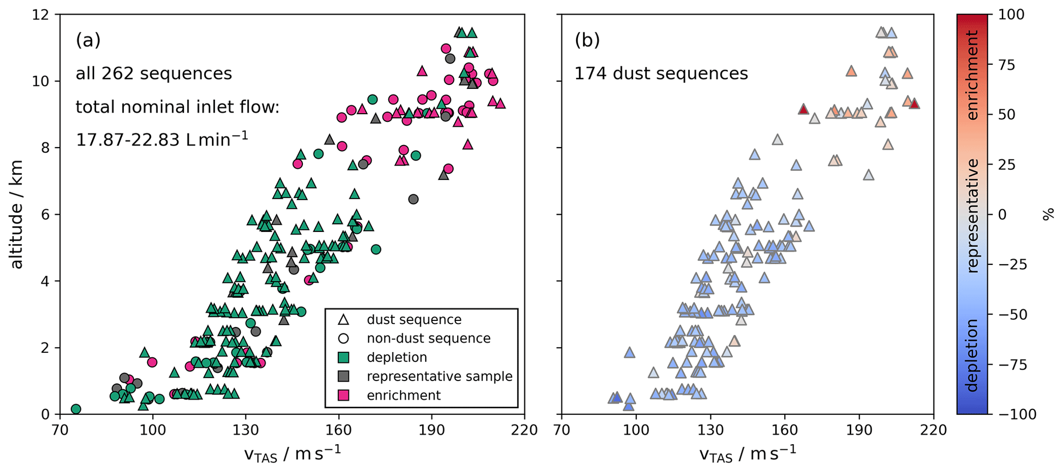
Figure 4Vertical profile of mean vTAS as a function of mean altitude for (a) all 262 A-LIFE flight sequences and (b) the A-LIFE mineral dust sequences. (a) The shape of the markers indicates the presence of mineral dust during the sequence, and the color represents the sampling condition including depletion (), representative sample (), and enrichment (). Panel (b) is restricted to the 174 A-LIFE dust sequences. The color coding illustrates the strength of the deviation of the in-cabin and the full-size-range particle number concentration in the size range from 1 to 10 µm (given in percentages; see also Table 1). In both panels, it is visible that enrichment cases occur at the higher end of observed vTAS values.
3.2 Cutoff diameter of the sampling system aboard the Falcon research aircraft
Figure 5a depicts the experimentally determined cutoff diameters of the A-LIFE sampling system (inlet and sampling lines of the transport system) as a function of vTAS for all 174 A-LIFE mineral dust sequences. The cutoff diameters span a large range from about 1.1 to 9.2 µm. In general, for increasing vTAS values, also increases. Note that these cutoff diameters are also affected by the length and geometry (e.g., number of bends and horizontal or vertical tubing lines) of the sampling lines connecting the SkyOPC with the Falcon aerosol inlet. A difference in the sampling line length and geometry of the aerosol transport system would also change the cutoff diameter of the entire sampling system (see Fig. 7 for the transport efficiency of the nephelometer and TAP). For example, the transport efficiency of the nephelometer shows a cutoff diameter which is about 26 % smaller than for the SkyOPC due to longer sampling lines.
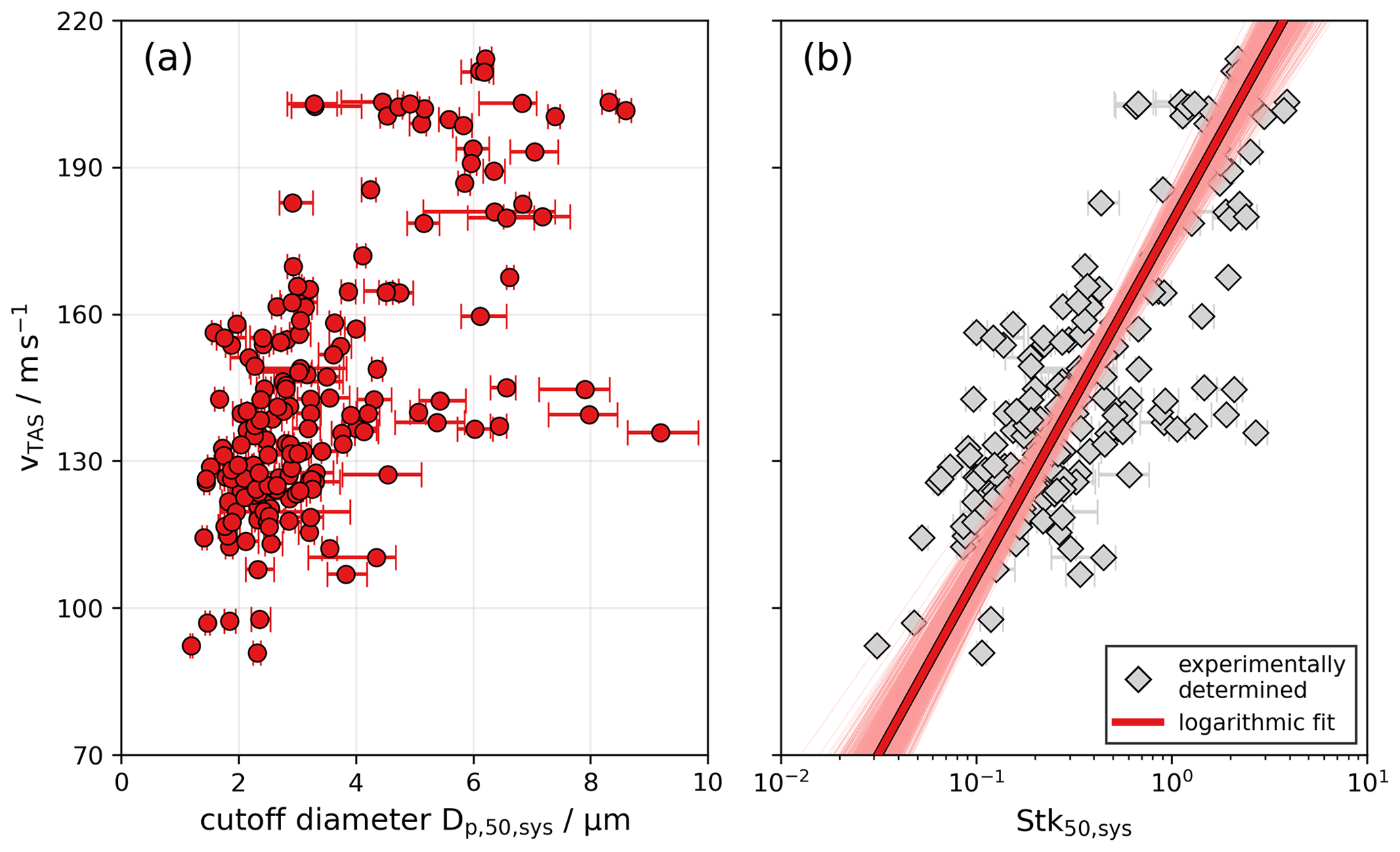
Figure 5(a) Experimentally derived cutoff diameters of the Falcon aerosol sampling system (inlet + tubing lines) for the 174 A-LIFE mineral dust sequences as a function of true airspeed vTAS. (b) Corresponding Stokes number for 50 % sampling efficiency as a function of vTAS. The red line represents a logarithmic fit of Stk50,sys as a function of vTAS. The shaded red area indicates the fit uncertainty.
Figure 5b illustrates the corresponding Stokes number for 50 % sampling efficiency Stk50,sys as a function of vTAS for all 174 A-LIFE dust sequences. The median Stk50,sys for vTAS below 160 m s−1 is 0.20, while for larger vTAS values it is 1.41, which deviates by 1 order of magnitude. Consequently, a logarithmic function was chosen to fit the Stk50,sys values as a function of vTAS between 70 and 220 m s−1.
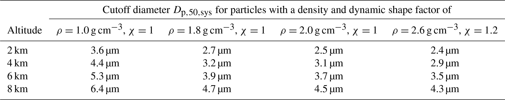
The cutoff diameter of the Falcon aerosol sampling system was also assessed for different aerosol types characterized by different particle densities. This was achieved by converting the fitted Stk50 values for the vTAS range from 70 to 220 m s−1 to cutoff diameters under the assumption of different particle densities. Figure 6 shows the results for four different particle densities. Although a vTAS can vary substantially at a given flight altitude as shown in Fig. 2, a corresponding mean flight altitude for a vTAS ranging between 120 and 180 m s−1 is included on the right side of the ordinate of Fig. 6. Similar to the experimentally determined cutoff diameters in Fig. 5a, the derived cutoff diameters also increase with an increasing vTAS. As expected, a larger cutoff diameter is observed for smaller particle densities. For unit density, the cutoff diameters range from 3.6 µm at a flight altitude of 2 km to 6.4 µm at 8 km. Doubling of the particle density (2 g cm−3) decreases the cutoff diameter to 2.5 µm at 2 km and to 4.5 µm at 8 km. An overview of the derived cutoff diameters for different particle densities at different flight altitudes is given in Table 2.
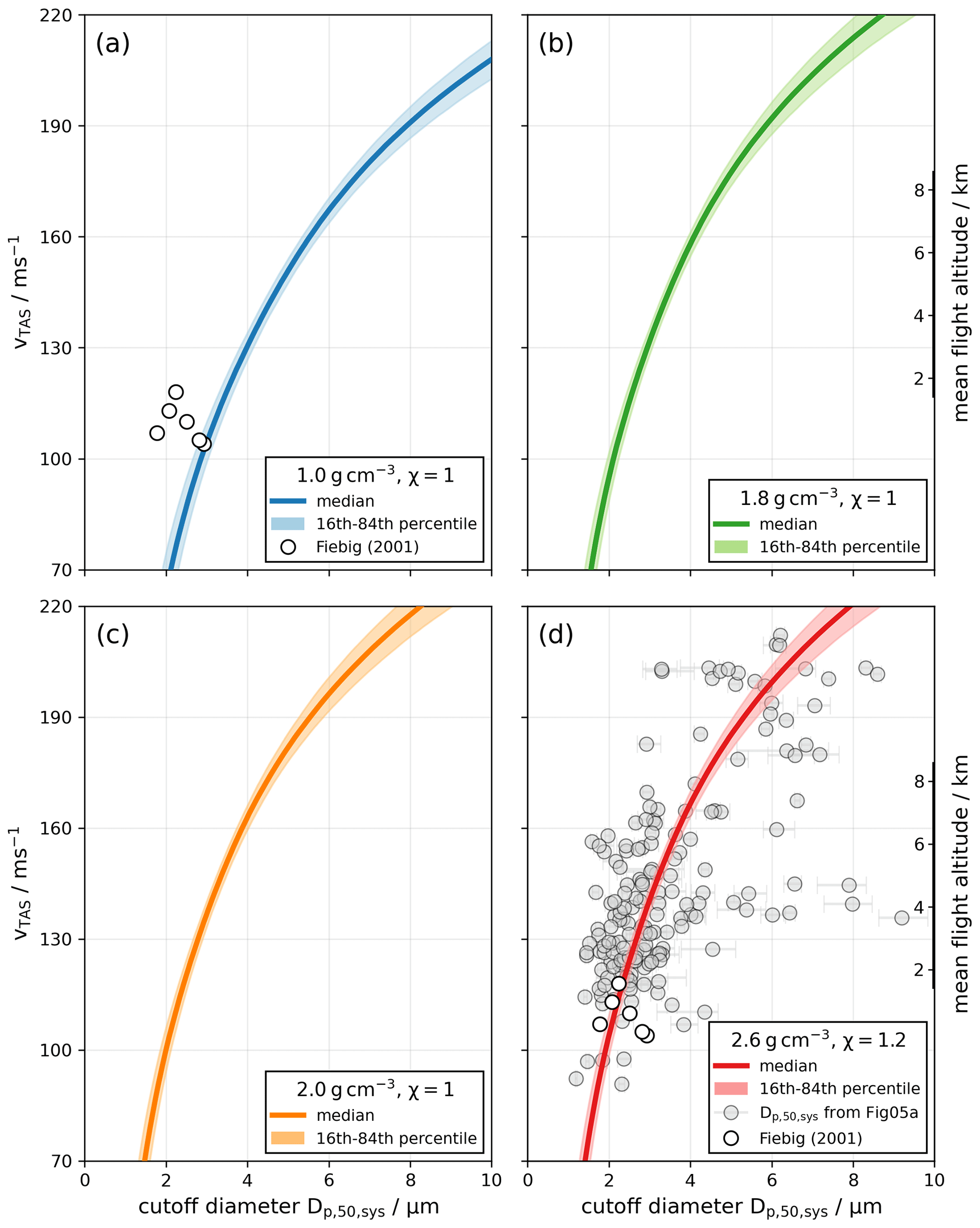
Figure 6Cutoff diameter of the sampling system as a function of vTAS for four different particle densities (a–d) derived from the logarithmic fit of the Stokes number shown in Fig. 5b. On the right y axes a mean altitude to the corresponding vTAS ranging from roughly 2 to 8 km is shown. In panels (a) and (d) the experimentally derived cutoff diameters from Fiebig (2001) are included. Panel (d) also shows the derived cutoff diameters from the NSDs in Fig. 5a.
Table 2Summary of derived cutoff diameters of the sampling system (i.e., combined effect of inlet and sampling lines) from Fig. 6 for different particle densities at different flight altitudes.
3.3 Sampling system efficiencies for different airspeed ranges
In Sect. 3.2, the experimentally determined cutoff diameters of the A-LIFE sampling system were presented as a function of vTAS and for different particle densities. In this section, the sampling efficiency of the A-LIFE aerosol sampling system is presented for different airspeed ranges as a function of particle diameter. Furthermore, the inlet efficiency is derived as a function of particle diameter by dividing the experimentally derived sampling efficiencies by the theoretically derived transport efficiency of the SkyOPC. For all cases with particle depletion, the particle size with 50 % efficiency was determined for all three efficiencies. An overview of the determined cutoff diameters of the sampling system (), inlet system (), and transport system () for different airspeed ranges during A-LIFE dust sequences is given in Table 3.
Table 3Overview of the determined cutoff diameters (A-LIFE transport system, Falcon aerosol inlet, and sampling system) for different vTAS ranges during the A-LIFE aircraft field campaign. The experimentally determined cutoff diameters for the sampling system were derived from measurements in mineral dust sequences (particle density of about 2.6 g cm−3). The cutoff diameters for the transport system were theoretically calculated also assuming a particle density of 2.6 g cm−3 and a particle dynamic shape factor of 1.2. Consequently, the cutoff diameter of the Falcon aerosol inlet also refers to a particle density of 2.6 g cm−3.
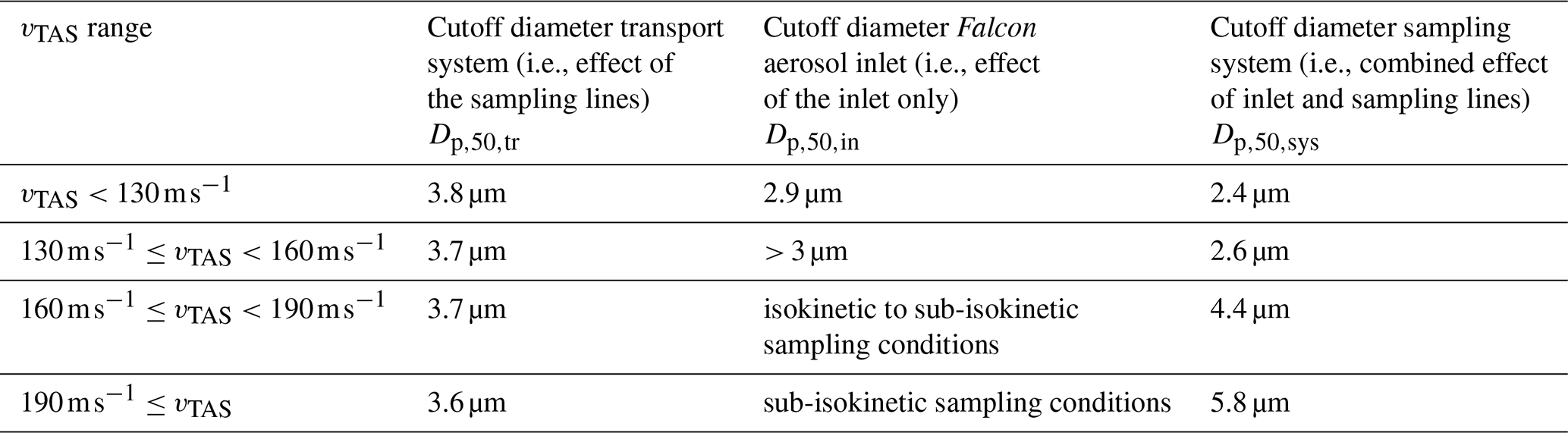
Figure 7 shows the theoretically calculated transport efficiency ηtr for various measurement devices including the SkyOPC, an Aurora 4000 nephelometer, and a tricolor absorption photometer (TAP) over an ambient pressure range from 283 to 796 hPa (which are the average values for the first and last vTAS range). The transport efficiency of the SkyOPC is depicted in violet. The violet line shows the case of mineral dust, which is used in this study to derive the inlet efficiency during dust sequences. For comparison, the violet–black striped line depicts the corresponding transport efficiency for particles with a density of 1 g cm−3 and a dynamic shape factor of 1. The upper cutoff diameter (i.e., the 50 % cutoff diameter at the larger end of the particle size distribution) for the A-LIFE transport system inside the aircraft cabin for the SkyOPC ranges from 3.6 µm at 283 hPa to 3.8 µm at 796 hPa for mineral dust particles, which suggests that a changing ambient pressure only has a minor influence on the transport efficiency for coarse-mode aerosol particles in the A-LIFE transport system inside the aircraft cabin. The increases to 5.4 µm at 283 hPa to 5.6 µm at 796 hPa for particles with a unit density and unit dynamic shape factor. For comparison, Fig. 7 also shows the theoretically calculated transport efficiency for the nephelometer and the TAP instruments which show upper cutoff diameters that are 25 %–27 % and 26 %–28 % smaller compared to the SkyOPC due to the longer sampling lines (see Table S1).
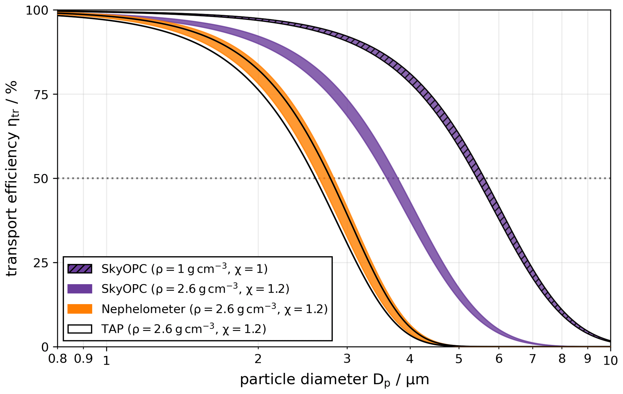
Figure 7Transport efficiency for three different in-cabin instruments deployed during A-LIFE focussing on the coarse-mode size range. For all calculations mineral dust particles were assumed with a particle density of 2.6 g cm−3 and a dynamic shape factor of 1.2. For the SkyOPC, the transport efficiency was also calculated for particles with a unit density and unit dynamic shape factor (violet–black striped line). The computations cover the ambient pressure range from 283 to 796 hPa (which are the average values for the first and the last vTAS range as defined in Sect. 2.4.2) represented by the width of the lines and assume an in-cabin temperature of 30 °C.
Figure 8 shows the measured sampling efficiency ηsys (left column, blue lines), the calculated transport efficiency ηtr of the SkyOPC (right column, violet lines), and the inferred Falcon aerosol inlet efficiency ηin (right column, green lines) as a function of particle diameter Dp during dust sequences. Each row represents a specific vTAS range. The sampling efficiencies were derived from the log-normal fitted NSDs extending to 10 µm diameter, whereas the inlet efficiencies are only given for the measurement size range of the SkyOPC up to 3 µm.
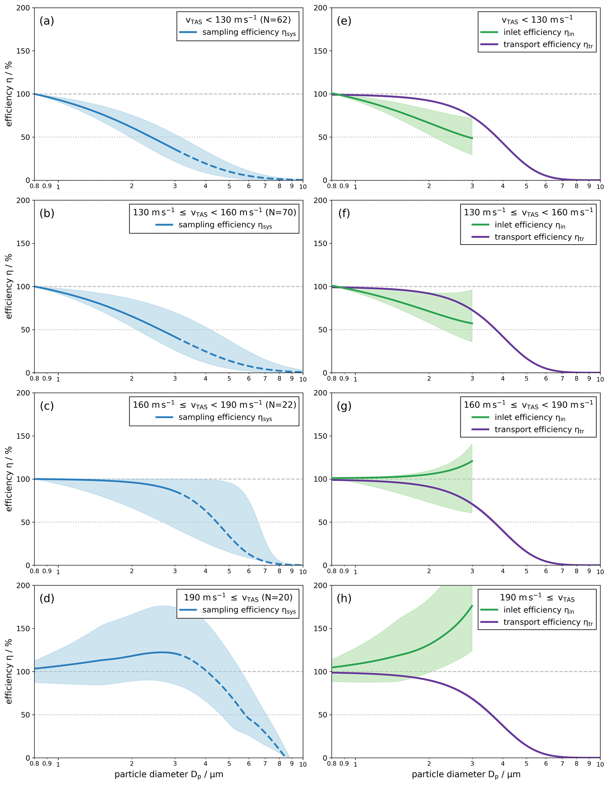
Figure 8Sampling efficiency (a–d) and inlet and transport efficiency (e–h) as a function of particle diameter Dp. Each row represents a specific vTAS range. The dark-blue line of the sampling efficiency indicates the median of all calculations, while the light-blue area shows the uncertainty range between the 16th and 84th percentile. The solid blue line indicates the measurement range of the SkyOPC. Above ∼3 µm in diameter (dashed blue line), data from the in-cabin NSD fit were used to derive the sampling efficiency. The transport efficiency shows theoretical calculations for the transport system of the SkyOPC. The inlet efficiency was derived from the experimental approach for the sampling efficiency and the theoretical calculations for the transport efficiency and is shown here up to a particle diameter of 3 µm.
In general, for an increasing vTAS and therefore increasing altitude, an increasing cutoff diameter of the sampling system is observed. While the only increases slightly from the first to the second vTAS range (from 2.4 µm in Fig. 8a to 2.6 µm in Fig. 8b), the differences are larger for the last two vTAS classes ( increased from 4.5 µm in Fig. 8c to 5.9 µm in Fig. 8d). Up to a vTAS of 190 m s−1, the averaged sampling efficiencies stay below 100 % along the entire particle diameter range. Only the last vTAS range (Fig. 8d) shows values that exceed 100 % which can be associated with the enrichment of coarse-mode particles due to the Falcon aerosol inlet. For a vTAS higher than 190 m s−1, the sampling efficiency reaches a maximum of 122 % at a particle diameter of 2.7 µm. For larger particles, the sampling efficiency shows a steep decrease with values of less than 100 % for particle diameters larger than 4.0 µm.
The inlet efficiencies ηin (green lines in Fig. 8e–h) show the following behavior: in the first two vTAS ranges below 160 m s−1 (Fig. 8e and f), the inlet efficiencies indicate a depletion of coarse-mode particles in the inlet system. In the first vTAS range, the cutoff diameter of the inlet system is about 2.9 µm. In the second vTAS range, the inlet efficiency did not drop below 50 %, suggesting that the cutoff diameter has to be larger than 3 µm. Between a vTAS of 160 and 190 m s−1 (Fig. 8g), the data reveal an inlet efficiency of nearly 100 % with a slight tendency of enrichment starting at particle diameters of approximately 2.0 µm. For (Fig. 8h), coarse-mode particles are enriched in the inlet system with an enrichment factor of 1.31 at a particle diameter of 2.0 µm which increases to 1.76 at a 3.0 µm particle diameter.
4.1 Characterization of the Falcon sampling system
From the characterization of the sampling system of the Falcon research aircraft, two major findings emerged. First, the sampling efficiency is highly dependent on the true airspeed of the aircraft with respect to the surrounding air mass. During A-LIFE we encountered all three different sampling conditions (sub-isokinetic, isokinetic, and super-isokinetic) which have different influences on the sampling of coarse-mode aerosol particles with in-cabin instruments. A key step for characterizing the Falcon aerosol sampling system was to group the flight sequences according to the vTAS instead of the flight altitude since the velocities in and outside the sampling system are the physical parameters that govern the sampling conditions.
Second, the results of this study show the significance that sampling efficiencies always have to be considered to be a combination of both the inlet and the transport efficiency. The combination of the two efficiencies is especially evident in the sampling efficiency of the largest vTAS range (; Fig. 8d and h). Theoretical estimations of the inlet efficiency at sub-isokinetic sampling conditions suggest an increasing enhancement for increasing particle size. However, Fig. 8 shows that an enhancement of particles only occurs up to a particle diameter of around 4 µm (with a peak at 2.7 µm). For larger particles, the losses through the sampling lines are stronger than the enhancement due to the inlet, which leads to a rapidly dropping sampling efficiency of the entire aerosol sampling system. This underlines the important role of the transport efficiency in the overall detection efficiency of aerosol particles.
As mentioned in Sect. 1, Fiebig (2001) calculated the cutoff diameters of the sampling system aboard the Falcon as a function of flight altitude. For the isokinetic Falcon aerosol inlet, six cutoff diameters and the corresponding Stokes number were experimentally derived from instrument data collected within the LACE 98 experiment within a vTAS range between 104 and 118 m s−1 under super-isokinetic sampling conditions (resulting in a depletion of coarse-mode particles at the inlet system). These results were taken to calculate one mean value of the Stokes number Stk ± 0.137, which was used to convert the cutoff diameters for the entire altitude range of the Falcon assuming altitude-dependent average values for ambient temperature, pressure, and airspeed. The main aerosol types and therefore the particle density during the investigated flight sequences, used to derive the cutoff diameters, were not specified in Fiebig (2001). Therefore, we included the data points from Fiebig (2001) in Fig. 6a and d for comparison, thereby covering the range of particle densities between 1.0 and 2.6 g cm−3. The smaller cutoff diameters from Fiebig (2001) match with our derived cutoff diameters for a particle density of 2.6 g cm−3 (see Fig. 6d), while the larger cutoff diameters are in agreement with our derived cutoff diameters for a unit particle density (see Fig. 6a). The cutoff diameters from Fiebig (2001) are consistent with our results for particle densities between 1.0 and 2.6 g cm−3 despite several differences in the setup. For example, the total flow velocity of the in-cabin instrumentation during the LACE 98 aircraft project was 27.3 m s−1, much larger than during A-LIFE where the total flow velocity was 15 % to 33 % smaller. Furthermore, the geometry of the transport system was very likely different from the A-LIFE in-cabin setup. Although the experimentally determined in this study agrees with what is referred to as cutoff diameters in Fiebig (2001), the altitude-dependent cutoff diameters inferred from the Stokes number are different in this study: in Fiebig (2001), the cutoff diameter decreases (for particles with a unit density) from 2.3 µm at ground level to 1.7 µm at around 8 km altitude as a result of using the same mean Stokes number for the entire altitude range. As visible from Eq. (3), keeping the Stokes number constant while increasing the altitude leads to an increase in the true airspeed of the aircraft which causes decreasing cutoff diameters with altitude. We believe that continuous values of the Stokes number over the entire airspeed range are needed to cover all three sampling conditions. The A-LIFE data set enabled us to determine the cutoff diameters during three different sampling conditions (sub-isokinetic, isokinetic, and super-isokinetic), and the results show an increasing value of for an increasing altitude and airspeed (see Fig. 6).
4.2 Uncertainties and limitations of the study
Every study is subject to uncertainties and limitations. In the following paragraphs we discuss different aspects that have to be kept in mind when referring to the results of this study.
4.2.1 Fixed total volumetric flow
As mentioned in Sect. 1, the ratio between the ambient air velocity and the stream velocity inside the inlet plays a crucial role in enabling the measurement of a representative sample of aerosol particles. During the A-LIFE campaign, the in-cabin instrumentation was always fully operated, which means that the stream velocity inside the inlet was always in the range between 18.14 and 23.18 m s−1. During A-LIFE, as well as in previous studies, the in-cabin volume airflow in the Falcon aerosol sampling system was not controlled (e.g., Minikin et al., 2003; Petzold et al., 2009; Schumann et al., 2011; Weinzierl et al., 2017; Moore et al., 2017). Therefore, isokinetic flow conditions were only matched at certain flight altitudes. Future measurement campaigns with the Falcon could have a different total volumetric flow (e.g., due to another set of in-cabin instruments), which could lead to sampling conditions occurring at other airspeeds compared to this study. According to the ratio, with a lower total volume flow, the enhancement effect is expected to already happen at lower airspeeds and therefore lower flight altitudes.
4.2.2 Aerosol inlet system of the Falcon
The theory behind the possible depletion or enhancement of coarse-mode aerosol particles is, strictly speaking, only valid for the inlet opening of a sampling tube and can be described with the particle-size-dependent inlet efficiency ηin (see Belyaev and Levin, 1972, 1974; Hinds, 1999, or Brockmann, 2011). Here, we assign the inlet efficiency to the whole inlet system shown in Fig. 1 that transports the ambient aerosol particles from the environment to the transport system components inside the aircraft. This includes the diffuser, the tube with the 90° bend, and the isokinetic inlet tube (see Fig. 1). However, this inlet system is used for every flight with the Falcon and does not change during different measurement campaigns. Therefore, it might be plausible to describe this inlet system with one particle-size-dependent transmission efficiency ηin. It is also worth mentioning that nearly isokinetic sampling conditions are present in the third vTAS range (; Fig. 8g), where the inlet efficiency is about 100 % up to a particle size of 2 µm, while such conditions are predicted (see Sect. 2.2) in a lower vTAS range between 129 and 165 m s−1. A possible explanation for this might be that we assign only one inlet efficiency to the whole inlet system as just described above.
4.2.3 Combination of experimentally derived efficiencies with theoretical calculations
In order to estimate the inlet efficiency, the sampling efficiency and the transport efficiency have to be known (see Eq. 1). In this study, the transport efficiency was derived with empirical equations from literature in the particle diameter range from 800 nm to 10 µm. The resulting transport efficiencies show an exponential decrease for particles larger than ∼ 2–3 µm (Fig. 7). The experimentally derived sampling efficiencies were determined from the log-normal parameterized NSD. For the in-cabin NSD, the data from the SkyOPC were used, which has an upper size detection limit of about 3 µm in the setting used during A-LIFE. Beyond 3 µm, the fit of the in-cabin NSD was used up to 10 µm in diameter (see also Fig. 3). Note that the log-normal fits were restricted so that the number concentration from the NSDs in the size range between 10 nm and 50 µm matched the integral particle number concentration measured with a CPC. Hence, the sampling efficiencies for particles larger than 3 µm are based on the log-normal fits (dashed blue line in left column of Fig. 8). By comparing the sampling and transport efficiency, one can see that the sampling efficiency does not decrease as steep as the theoretical transport efficiencies, which leads to inlet efficiencies with higher uncertainties. Due to this reason, the inlet efficiencies are only shown up to a particle size of 3 µm in Fig. 8.
4.2.4 Coarse-mode aerosol composition
For the derivation of the sampling efficiencies, we focussed only on the dust cases, based on the aerosol classification for the A-LIFE campaign (Weinzierl et al., 2024). According to the FLEXPART model, these cases provided a major contribution of mineral dust particles in the coarse-mode size range from 1 to 10 µm in diameter. The dust contribution during these flight sequences accumulated to 91 % among all aerosol types when averaging the FLEXPART data. Hence, this approach was chosen to enable the derivation of the Stokes number with a better-constrained choice of particle density and dynamic shape factor. However, the sampling efficiency shown in this paper may differ if the majority of the coarse-mode particles are not mineral dust particles but particles that have a different density and thus inertia (e.g., sea salt and sulfate, which have a lower density than mineral dust; see Hess et al., 1998).
Obtaining measurements of ambient aerosol particles inside the cabin of a fast-flying research aircraft is a challenging task due to high airspeeds and to changing ambient conditions. In particular, for high-quality coarse-mode aerosol measurements, an understanding of particle losses and enhancements in the aerosol sampling system (formed by the inlet and the transport system) is crucial. The aim of this study was to characterize the aerosol sampling system aboard the Falcon research aircraft. The characterization was carried out using data from the A-LIFE aircraft field experiment in April 2017. The A-LIFE data set was divided into 262 flight sequences at a constant altitude with homogenous aerosol conditions outside of clouds. In-cabin and full-size-range particle number size distributions were calculated for each flight sequence and were key inputs for the characterization of the Falcon aerosol sampling system. Each flight sequence at a constant altitude was assigned to one of three groups: depletion (), representative sample (), or enrichment (); this was done based on the true airspeed of the research aircraft, and particle-size-dependent sampling efficiencies were calculated for different true airspeed ranges. The cutoff diameter (50 % sampling efficiency) of the sampling system was also determined as a function of true airspeed for each constant altitude flight sequence with a major contribution of mineral dust particles. Based on the experimentally derived Stokes numbers, the cutoff diameters were calculated for different particle densities as a function of true airspeed.
During the A-LIFE field experiment, the Falcon research aircraft flew with true airspeeds (in this study described as vTAS) between roughly 70 and 220 m s−1, which means that all three sampling conditions (sub-isokinetic, isokinetic, and super-isokinetic) were encountered during the project. As described earlier, the Falcon aerosol inlet uses a diffuser to slow down the air by a factor of 7.1, and the in-cabin aerosol instrumentation operated during A-LIFE drew a total volume flow which ranged between 17.87–22.83 L min−1 at the isokinetic inlet's entry. A depletion of coarse-mode particles due to the sampling system was observed during most of the flight sequences at the lowest mean vTAS of about 136 ± 23 m s−1. Representative samples of ambient aerosol particles were detected by the in-cabin instrumentation (referring to isokinetic sampling conditions) at a mean vTAS of 146 ± 35 m s−1. Enrichment of coarse-mode particles happened at a vTAS of 177 ± 31 m s−1. The results of the sampling condition classifications show that the velocity of the research aircraft has a major impact on the sampling efficiency of coarse-mode aerosol particles with in-cabin instruments. Contrary to past studies, where often the flight altitude was used to characterize the sampling system, we recommend using the airspeed of the aircraft with respect to the surrounding air mass (true airspeed) for the characterization since vTAS, together with the flow velocity drawn by the aerosol instrumentation, determines the ratio (see Sect. 1).
The measured particle-size-dependent sampling efficiencies during dust sequences show that up to a vTAS of 190 m s−1, in most cases, only losses of particles occur in the sampling system. For a higher vTAS, a size-dependent enhancement effect was observed up to a particle diameter of 4.0 µm with a maximum at 2.6 µm. Even larger particles are still enhanced in the inlet system, but inertial and gravitational particle losses in the transport system get more and more pronounced, which leads to a decreasing overall efficiency of the aerosol sampling system. This demonstrates the importance of considering both inlet and transport efficiency when quantifying the overall sampling efficiency of an aerosol inlet system.
The cutoff diameters were derived from the particle-size-dependent sampling efficiencies. The results show that the cutoff diameters increase with an increasing vTAS, which is in accordance with the previously demonstrated presence of an enhancement effect of coarse-mode particles at high vTAS. Using the corresponding Stokes number Stk50,sys as a function of vTAS, the cutoff diameters were calculated for four different particle densities (1.0, 1.8, 2.0, and 2.6 g cm−3). For a higher particle density, lower cutoff diameters result over the entire vTAS range.
In an ideal aerosol sampling system on a research aircraft, the volumetric flow of the in-cabin instrumentation should match the estimated (and by the diffuser decelerated) airspeed at all flight altitudes. This may be achieved by a controllable flow that matches the actual airspeed everywhere to always allow near-isokinetic sampling conditions (), e.g., through adding a controllable bypass flow. In cases when the in-cabin instrumentation already needs a high flow, this may require adding an additional aerosol inlet. Furthermore, sampling lines should be designed to be as short as possible and to contain as few bends as possible to avoid losses. Instruments measuring at both ends of the size distribution should be installed as close as possible to the inlet to minimize diffusional (small particles) losses as well as gravitational and inertial (large particles) losses. However, external factors (e.g., airworthiness certification restrictions, limitations in the number of aerosol inlets, and limited space for instruments near the inlet) often constrain the sampling setup so that it is not always possible to deploy a near-ideal aerosol sampling system. In any case, it is important to know the limitations of the aerosol sampling system consisting of both the inlet and the transport system.
The data of the main results of this study (sampling, inlet, and transport efficiencies and cutoff diameters for different particle densities) are publicly available in the data archive Phaidra of the University of Vienna (https://doi.org/10.25365/phaidra.368, Schöberl et al., 2024). The in-cabin and full-size-range NSD that were applied in this study will be provided in the course of the A-LIFE overview paper (Weinzierl et al., 2024).
The supplement related to this article is available online at: https://doi.org/10.5194/amt-17-2761-2024-supplement.
MS and BW conceptualized the study. MS analyzed the data and wrote the manuscript with the help of BW. BW coordinated the A-LIFE project. BW and MD performed the aerosol measurements during the A-LIFE field campaign. AT and PS performed the FLEXPART simulations. MS, MD, and JG calculated the combined number size distributions. All coauthors participated in the scientific discussion and reviewed the manuscript.
The contact author has declared that none of the authors has any competing interests.
The views expressed in this study are those of the authors and do not necessarily represent the views of the CTBTO Preparatory Commission.
Publisher's note: Copernicus Publications remains neutral with regard to jurisdictional claims made in the text, published maps, institutional affiliations, or any other geographical representation in this paper. While Copernicus Publications makes every effort to include appropriate place names, the final responsibility lies with the authors.
We thank the A-LIFE team and our local hosts in Cyprus for their support and great collaboration during the A-LIFE field experiment. We are grateful to the DLR Institute of Atmospheric Physics and the DLR Flight Experiments, in particular to Andrea Hausold, the pilots, and the technical and sensor team from DLR flight operations for their great support. We would like to thank Heidi Huntrieser (DLR) and Robert Wagner (TROPOS) for preparing the A-LIFE weather forecasts and for their help with flight planning. We thank Andreas Minikin, Daniel Sauer, and Georg Dietz (all DLR) for their help with questions about mounting and inclination of the Falcon aerosol inlet. We thank GeoSphere Austria (formerly ZAMG) for providing access to ECMWF forecast data to calculate the trajectories in real time, and we also thank the Copernicus Atmosphere Monitoring Service (CAMS) user support team. CAMS information, partly modified, was used for this paper; neither the European Commission nor ECMWF is responsible for any use that may be made of the information.
This research has been supported by the European Research Council (ERC), H2020 European Research Council (grant no. 640458 (A-LIFE)), and the European Space Agency (ESA; contract no. 4000125810/18/NL/CT/gp (A-CARE)). In addition, the German Aerospace Center (DLR) provided funding for a significant number of flight hours and aircraft allocation days for the A-LIFE aircraft field experiment. Two EUFAR (EUropean FAcility for Airborne Research) projects were also clustered with A-LIFE and provided funding for 16 flight hours. This research has also been supported by the University of Vienna (Vienna Doctoral School in Physics, VDSP). Open-access funding was provided by the University of Vienna.
This paper was edited by Johannes Schneider and reviewed by Darrel Baumgardner and two anonymous referees.
Ansmann, A., Wandinger, U., Wiedensohler, A., and Leiterer, U.: Lindenberg Aerosol Characterization Experiment 1998 (LACE 98): Overview, J. Geophys. Res.-Atmos., 107, LAC 11-1–LAC 11-12, https://doi.org/10.1029/2000JD000233, 2002.
Baumgardner, D. and Huebert, B.: The airborne aerosol inlet workshop: Meeting report, J. Aerosol Sci., 24, 835–846, https://doi.org/10.1016/0021-8502(93)90050-J, 1993.
Belyaev, S. P. and Levin, L. M.: Investigation of aerosol aspiration by photographing particle tracks under flash illumination, J. Aerosol Sci., 3, 127–140, https://doi.org/10.1016/0021-8502(72)90149-8, 1972.
Belyaev, S. P. and Levin, L. M.: Techniques for collection of representative aerosol samples, J. Aerosol Sci., 5, 325–338, https://doi.org/10.1016/0021-8502(74)90130-X, 1974.
Bögel, W. and Baumann, R.: Test and Calibration of the DLR Falcon Wind Measuring System by Maneuvers, J. Atmos. Ocean. Tech., 8, 5–18, https://doi.org/10.1175/1520-0426(1991)008<0005:TACOTD>2.0.CO;2, 1991.
Boucher, O., Randall, D., Artaxo, P., Bretherton, C., Feingold, G., Forster, P. M., Kerminen, V.-M., Kondo, Y., Liao, H., Lohmann, U., Rasch, P., Satheesh, S. K., Sherwood, S., Stevens, B., and Zhang, X. Y.: IPCC: Climate Change 2013: The Physical Science Basis. Contribution of Working Group I to the Fifth Assessment Report of the Intergovernmental Panel on Climate Change, edited by: Stocker, T. F., Qin, D., Plattner, G.-K., Tignor, M., Allen, S. K., Boschung, J., Nauels, A., Xia, Y., Bex, V., and Midgley, P. M., Cambridge University Press, ISBN: 978-1-107-05799-1, 2013.
Brockmann, J. E.: Aerosol Transport in Sampling Lines and Inlets, in: Aerosol Measurement, edited by: Kulkarni, P., Baron, P. A., and Willeke, K., John Wiley & Sons, Inc., Hoboken, NJ, USA, 68–105, https://doi.org/10.1002/9781118001684.ch6, 2011.
Dhaniyala, S., Flagan, R. C., McKinney, K. A., and Wennberg, P. O.: Novel Aerosol/Gas Inlet for Aircraft-Based Measurements, Aerosol Sci. Tech., 37, 828–840, https://doi.org/10.1080/02786820300937, 2003.
Dollner, M.: Assessment of the global distribution of coarse-mode aerosol and clouds with large-scale in situ aircraft observations, PhD thesis, Universität Wien, Vienna, https://doi.org/10.25365/THESIS.72087, 2022.
Dollner, M., Gasteiger, J., Schöberl, M., Gattringer, A., Beres, N. D., Bui, P. T., Diskin, G., and Weinzierl, B.: The Cloud Indicator: A Novel Algorithm for Automatic Detection and Classification of Clouds Using Airborne in Situ Observations, SSRN [preprint], https://doi.org/10.2139/ssrn.4654136, 2023.
Fiebig, M.: Das troposphärische Aerosol in mittleren Breiten Mikrophysik, Optik und Klimaantrieb am Beispiel der Feldstudie LACE 98, PhD thesis, Ludwig-Maximilians-Universität, Munich, 2001.
Fuchs, N.: The Mechanics of Aerosols, Pergamon, Oxford, https://doi.org/10.1002/qj.49709138822, 1964.
Hegg, D. A., Covert, D. S., Jonsson, H., and Covert, P. A.: Determination of the Transmission Efficiency of an Aircraft Aerosol Inlet, Aerosol Sci. Tech., 39, 966–971, https://doi.org/10.1080/02786820500377814, 2005.
Hermann, M., Stratmann, F., Wilck, M., and Wiedensohler, A.: Sampling Characteristics of an Aircraft-Borne Aerosol Inlet System, J. Atmos. Ocean. Tech., 18, 7–19, https://doi.org/10.1175/1520-0426(2001)018<0007:SCOAAB>2.0.CO;2, 2001.
Hess, M., Koepke, P., and Schult, I.: Optical Properties of Aerosols and Clouds: The Software Package OPAC, B. Am. Meteorol. Soc., 79, 831–844, https://doi.org/10.1175/1520-0477(1998)079<0831:OPOAAC>2.0.CO;2, 1998.
Hinds, W. C.: Aerosol Technology, 2nd edn., John Wiley & Sons, New York, ISBN 978-0-471-19410-1, 1999.
Huebert, B. J., Lee, G., and Warren, W. L.: Airborne aerosol inlet passing efficiency measurement, J. Geophys. Res.-Atmos., 95, 16369–16381, https://doi.org/10.1029/JD095iD10p16369, 1990.
Kaaden, N., Massling, A., Schladitz, A., Müller, T., Kandler, K., Schütz, L., Weinzierl, B., Petzold, A., Tesche, M., Leinert, S., Deutscher, C., Ebert, M., Weinbruch, S., and Wiedensohler, A.: State of mixing, shape factor, number size distribution, and hygroscopic growth of the Saharan anthropogenic and mineral dust aerosol at Tinfou, Morocco, Tellus B, 61, 51–63, https://doi.org/10.1111/j.1600-0889.2008.00388.x, 2009.
Krämer, M. and Afchine, A.: Sampling characteristics of inlets operated at low ratios: new insights from computational fluid dynamics (CFX) modeling, J. Aerosol Sci., 35, 683–694, https://doi.org/10.1016/j.jaerosci.2003.11.011, 2004.
Mahowald, N., Albani, S., Kok, J. F., Engelstaeder, S., Scanza, R., Ward, D. S., and Flanner, M. G.: The size distribution of desert dust aerosols and its impact on the Earth system, Aeolian Res., 15, 53–71, https://doi.org/10.1016/j.aeolia.2013.09.002, 2014.
McNaughton, C. S., Clarke, A. D., Howell, S. G., Pinkerton, M., Anderson, B., Thornhill, L., Hudgins, C., Winstead, E., Dibb, J. E., Scheuer, E., and Maring, H.: Results from the DC-8 Inlet Characterization Experiment (DICE): Airborne Versus Surface Sampling of Mineral Dust and Sea Salt Aerosols, Aerosol Sci. Tech., 41, 136–159, https://doi.org/10.1080/02786820601118406, 2007.
Minikin, A., Petzold, A., Ström, J., Krejci, R., Seifert, M., van Velthoven, P., Schlager, H., and Schumann, U.: Aircraft observations of the upper tropospheric fine particle aerosol in the Northern and Southern Hemispheres at midlatitudes, Geophys. Res. Lett., 30, 1503, https://doi.org/10.1029/2002GL016458, 2003.
Moore, R. H., Thornhill, K. L., Weinzierl, B., Sauer, D., D'Ascoli, E., Kim, J., Lichtenstern, M., Scheibe, M., Beaton, B., Beyersdorf, A. J., Barrick, J., Bulzan, D., Corr, C. A., Crosbie, E., Jurkat, T., Martin, R., Riddick, D., Shook, M., Slover, G., Voigt, C., White, R., Winstead, E., Yasky, R., Ziemba, L. D., Brown, A., Schlager, H., and Anderson, B. E.: Biofuel blending reduces particle emissions from aircraft engines at cruise conditions, Nature, 543, 411–415, https://doi.org/10.1038/nature21420, 2017.
Murphy, D. M., Cziczo, D. J., Hudson, P. K., Thomson, D. S., Wilson, J. C., Kojima, T., and Buseck, P. R.: Particle Generation and Resuspension in Aircraft Inlets when Flying in Clouds, Aerosol Sci. Tech., 38, 401–409, https://doi.org/10.1080/02786820490443094, 2004.
Perring, A. E., Schwarz, J. P., Gao, R. S., Heymsfield, A. J., Schmitt, C. G., Schnaiter, M., and Fahey, D. W.: Evaluation of a Perpendicular Inlet for Airborne Sampling of Interstitial Submicron Black-Carbon Aerosol, Aerosol Sci. Tech., 47, 1066–1072, https://doi.org/10.1080/02786826.2013.821196, 2013.
Petzold, A., Rasp, K., Weinzierl, B., Esselborn, M., Hamburger, T., Dörnbrac, A., Kandler, K., Schütz, L., Knippertz, P., Fiebig, M., and Virkkula, A.: Saharan dust absorption and refractive index from aircraft-based observations during SAMUM 2006, Tellus B, 61, 118, https://doi.org/10.1111/j.1600-0889.2008.00383.x, 2009.
Porter, J. N., Clarke, A. D., Ferry, G., and Pueschel, R. F.: Aircraft studies of size-dependent aerosol sampling through inlets, J. Geophys. Res.-Atmos., 97, 3815–3824, https://doi.org/10.1029/91JD02886, 1992.
Pui, D. Y. H., Romay-Novas, F., and Liu, B. Y. H.: Experimental Study of Particle Deposition in Bends of Circular Cross Section, Aerosol Sci. Tech., 7, 301–315, https://doi.org/10.1080/02786828708959166, 1987.
Rosenberg, P. D., Dean, A. R., Williams, P. I., Dorsey, J. R., Minikin, A., Pickering, M. A., and Petzold, A.: Particle sizing calibration with refractive index correction for light scattering optical particle counters and impacts upon PCASP and CDP data collected during the Fennec campaign, Atmos. Meas. Tech., 5, 1147–1163, https://doi.org/10.5194/amt-5-1147-2012, 2012.
Schneider, J., Hings, S. S., Nele Hock, B., Weimer, S., Borrmann, S., Fiebig, M., Petzold, A., Busen, R., and Kärcher, B.: Aircraft-based operation of an aerosol mass spectrometer: Measurements of tropospheric aerosol composition, J. Aerosol Sci., 37, 839–857, https://doi.org/10.1016/j.jaerosci.2005.07.002, 2006.
Schöberl, M., Dollner, M., Gasteiger, J., Seibert, P., Tipka, A., and Weinzierl, B.: Data of Characterization of the airborne aerosol inlet and transport system used during the A-LIFE aircraft field experiement, Universität Wien [data set], https://doi.org/10.25365/phaidra.368, 2024.
Schumann, U. (Ed.): Atmospheric Physics: Background – Methods – Trends, Springer Berlin Heidelberg, Berlin, Heidelberg, https://doi.org/10.1007/978-3-642-30183-4, 2012.
Schumann, U., Weinzierl, B., Reitebuch, O., Schlager, H., Minikin, A., Forster, C., Baumann, R., Sailer, T., Graf, K., Mannstein, H., Voigt, C., Rahm, S., Simmet, R., Scheibe, M., Lichtenstern, M., Stock, P., Rüba, H., Schäuble, D., Tafferner, A., Rautenhaus, M., Gerz, T., Ziereis, H., Krautstrunk, M., Mallaun, C., Gayet, J.-F., Lieke, K., Kandler, K., Ebert, M., Weinbruch, S., Stohl, A., Gasteiger, J., Groß, S., Freudenthaler, V., Wiegner, M., Ansmann, A., Tesche, M., Olafsson, H., and Sturm, K.: Airborne observations of the Eyjafjalla volcano ash cloud over Europe during air space closure in April and May 2010, Atmos. Chem. Phys., 11, 2245–2279, https://doi.org/10.5194/acp-11-2245-2011, 2011.
Seebaugh, W.: Applications of principles of aerodynamics to inlet/diffuser design, in: Meeting Review: Airborne Aerosol Inlet Workshop, edited by: Baumgardner, D., Huebert, B., and Wilson, C., National Center for Atmospheric Research, Boulder, USA, 1991.
Seibert, P. and Frank, A.: Source-receptor matrix calculation with a Lagrangian particle dispersion model in backward mode, Atmos. Chem. Phys., 4, 51–63, https://doi.org/10.5194/acp-4-51-2004, 2004.
Seinfeld, J. H. and Pandis, S. N.: Atmospheric chemistry and physics: from air pollution to climate change, John Wiley & Sons, Hoboken, USA, 1326 pp., ISBN: 978-1-118-94740-1, 2016.
Sheridan, P. J. and Norton, R. B.: Determination of the passing efficiency for aerosol chemical species through a typical aircraft-mounted, diffuser-type aerosol inlet system, J. Geophys. Res.-Atmos., 103, 8215–8225, https://doi.org/10.1029/98JD00286, 1998.
Spanu, A., Dollner, M., Gasteiger, J., Bui, T. P., and Weinzierl, B.: Flow-induced errors in airborne in situ measurements of aerosols and clouds, Atmos. Meas. Tech., 13, 1963–1987, https://doi.org/10.5194/amt-13-1963-2020, 2020.
Stohl, A., Hittenberger, M., and Wotawa, G.: Validation of the lagrangian particle dispersion model FLEXPART against large-scale tracer experiment data, Atmos. Environ., 32, 4245–4264, https://doi.org/10.1016/S1352-2310(98)00184-8, 1998.
Thomas, J. W.: Gravity Settling of Particles in a Horizontal Tube, JAPCA J. Air Waste Ma., 8, 32–34, https://doi.org/10.1080/00966665.1958.10467825, 1958.
Walser, A., Sauer, D., Spanu, A., Gasteiger, J., and Weinzierl, B.: On the parametrization of optical particle counter response including instrument-induced broadening of size spectra and a self-consistent evaluation of calibration measurements, Atmos. Meas. Tech., 10, 4341–4361, https://doi.org/10.5194/amt-10-4341-2017, 2017.
Weinzierl, B., Ansmann, A., Prospero, J. M., Althausen, D., Benker, N., Chouza, F., Dollner, M., Farrell, D., Fomba, W. K., Freudenthaler, V., Gasteiger, J., Groß, S., Haarig, M., Heinold, B., Kandler, K., Kristensen, T. B., Mayol-Bracero, O. L., Müller, T., Reitebuch, O., Sauer, D., Schäfler, A., Schepanski, K., Spanu, A., Tegen, I., Toledano, C., and Walser, A.: The Saharan Aerosol Long-Range Transport and Aerosol–Cloud-Interaction Experiment: Overview and Selected Highlights, B. Am. Meteorol. Soc., 98, 1427–1451, https://doi.org/10.1175/BAMS-D-15-00142.1, 2017.
Weinzierl B., Dollner M., Gasteiger J., Teri M., Schöberl M., Heimerl K., Kupc A., Tipka A., Seibert P., Huntrieser H., Wagner R., Kandler K., Sudharaj A., Müller T., Brilke S., Fölker N., Sauer D., Reitebuch O., Groß S., Freudenthaler V., Toledano C., Haarig M., Mamouri R., Amiridis V., Ansmann A, and the A-LIFE Science Team: Investigating mineral dust mixtures in the Eastern Mediterranean: results from the A-LIFE aircraft field experiment, in preparation, 2024.
Wendisch, M. and Brenguier, J.-L.: Airborne Measurements for Environmental Research, John Wiley & Sons, https://doi.org/10.1002/9783527653218, 2013.
Wendisch, M., Coe, H., Baumgardner, D., Brenguier, J.-L., Dreiling, V., Fiebig, M., Formenti, P., Hermann, M., Krämer, M., Levin, Z., Maser, R., Mathieu, E., Nacass, P., Noone, K., Osborne, S., Schneider, J., Schütz, L., Schwarzenboeck, A., Stratmann, F., and Wilson, J.: Aircraft Particle Inlets: State-of-the-Art and Future Needs, B. Am. Meteorol. Soc., 85, 89–92, https://doi.org/10.1175/BAMS-85-1-89, 2004.
Wilson, J. C., Lafleu, B. G., Hilbert, H., Seebaugh, W. R., Fox, J., Gesler, D. W., Brock, C. A., Huebert, B. J., and Mullen, J.: Function and Performance of a Low Turbulence Inlet for Sampling Supermicron Particles from Aircraft Platforms, Aerosol Sci. Tech., 38, 790–802, https://doi.org/10.1080/027868290500841, 2004.
In the literature, a number of different size definitions exist for coarse-mode aerosol particles. Here, we follow the definitions of Mahowald et al. (2014) and Schumann (2012).
Note that in this study, we use the term “sampling system” to refer to both the inlet and sampling lines. We use the term “transport system” if we refer only to the sampling lines between the inlet and the instrumentation.
Note that the term “isokinetic inlet” in the context of the Falcon aerosol inlet has a historic background: in Fiebig (2001), the Falcon aerosol inlet was referred to as an “isokinetic inlet”. Also, in Schneider et al. (2006) it was named “isokinetic probe”. However, we want to point out that the inlet flow was never controlled with a bypass which would be necessary to maintain isokinetic sampling conditions for the entire operation range of the Falcon. Isokinetic sampling conditions were met only in a certain range of true airspeed as explained in this paper.