the Creative Commons Attribution 4.0 License.
the Creative Commons Attribution 4.0 License.
 | 12 Mar 2026
Ground-based HF to VHF radar calibration by scattering off a stratospheric balloon
Matthias Clahsen
Ralph Latteck
The knowledge of radar system properties is crucial for judging radar performance and correctly interpreting received raw and analysed data. The most critical part of that is the radiation pattern, which is often very difficult to measure for atmospheric/ionospheric sounding radars as the beam pointing direction is often almost vertical. Another fundamental aspect of multi-receiver radars is the accurate knowledge of receiver phases, which are a prerequisite for interferometry applications. Both topics present challenges for large-aperture radars, and are especially difficult for those operating in the lower high-frequency band. On 28 May 2024 the stratospheric balloon mission HELIX was launched with its payload at the Esrange Space Center, which later flew very close the Norwegian island Andøya. This drifting structure was seen on three co-located radar systems covering the lowermost HF (3.17 MHz) and the lower VHF (32.55 and 53.5 MHz) region. The detected backscatter was used to perform active phase calibration of the VHF system, which allowed the verification of the target positioning by interferometry for all three radars. Furthermore, it enabled the general confirmation of the two-way radiation pattern of all the systems.
- Article
(9801 KB) - Full-text XML
- BibTeX
- EndNote


Radar calibration efforts are essential for the correct, reliable and successful operation of radar systems and for the analysis of the collected data. Some radar properties and calibration parameters of the system can be directly measured, others can be inferred, while some even need to be assumed or anticipated. This information is indispensable to gain knowledge about the current status, its health and performance of the radar system. Some of the desirable parameters allow the comparison of radar experiments conducted with different radar systems, e.g. volume reflectivity of certain atmospheric radar targets (see e.g. Latteck et al., 2021). Furthermore, a reliable receiver phase calibration including the entire receiver chain from the antennas to the digitizers is essential for interferometric methods, e.g. Angle-of-Arrival estimations for meteor radar observations (AOA, see e.g. Holdsworth et al., 2004; Spargo, 2016) or for imaging techniques (Urco et al., 2019).
Without a solid understanding of the components involved in the system, the transmit radar beam could be widened or positioned away from the anticipated direction. Equivalently, for reception the phases for each receiver channel need to be known and stable for proper combination or interferometric use.
While for high-power VHF radars quite some options for radar calibration including the antenna array are available (see e.g. Mathews et al., 1988; Palmer et al., 1996; Chau et al., 2008; Gao and Mathews, 2014), things get very difficult at lower frequencies (see e.g. From and Whitehead, 1984; Tsutsumi et al., 1999; Bernhardt et al., 2008). Suitable targets for high frequency radars (HF, 3-30 MHz), with a size in the order of half of the wavelength and at sufficient distance to measure in the far field, are basically limited to horizontal (along Earth's curvature) propagation. Larger construction like buildings, communication or wind turbine towers etc. are suitable targets for even the lowermost end of the HF range. Quite recently floating platforms have been also used for calibration of HF radars (Wan et al., 2022). Similarly for atmospheric sounders with horizontal pointing in this frequency range echoes from E region layers may be utilized (e.g. Ponomarenko et al., 2018). Using such targets with highly directive vertical pointing radars won't yield much information as the involved antenna arrays are insensitive in these directions. For vertical mainbeam pointing radars applicable artificial targets are extremely rare and have been only envisioned (Bernhardt et al., 2008).
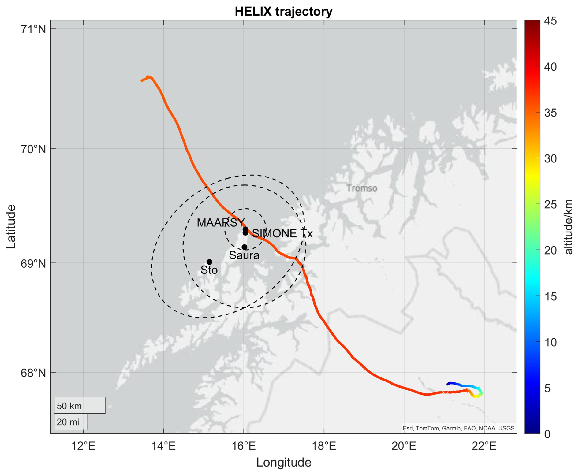
Figure 1Map of the HELIX trajectory starting in Kiruna/Sweden traversing over Northern Norway and near the radar systems on Andøya island. The dashed circles indicate the radars field of view for θ=30° (MAARSY) and θ=60° (Saura and SIMONe) at 35 km altitude. Map sources: Esri, TomTom, Garmin, FAO, NOAA, USGS.
As a fortunate coincidence on 28 May 2024 a stratospheric balloon was traveling near the island of Andøya in Northern Norway, where three atmospheric radar systems are operated spanning from nearly 3 to 53.5 MHz frequency (see a map in Fig. 1). This stratospheric balloon and its payload, mission named HELIX (The High Energy Light Isotope eXperiment program of direct cosmic-ray studies; HELIX Collaboration et al., 2023; StratoCat, 2023), was launched at the Esrange Space Center near Kiruna/Sweden (67.88° N, 21.12° E) and turned out to be a very useful radar calibration target. Given the rather remote radar location even airplanes of sufficient size do not likely fly anywhere near the radar main beam pointing at largest possible altitudes. Furthermore, the relatively high velocity might be a challenge for especially the 3 MHz radar as the typical experiment settings are optimized for targets at much greater distance and comparably less relative velocities.
In the following the earlier calibration efforts for the three radar systems involved in this study are summarized. Subsequently we will describe the analysis and applied methods for this radar calibration knowing the HELIX's GNSS trajectory. We will discuss the results and finish with the conclusions of these calibration efforts.
2.1 MAARSY – previous calibration experiments
The Middle Atmosphere Alomar Radar System (MAARSY) is a versatile high-power-large-aperture VHF radar, operated at 53.5 MHz, and built to conduct horizontally and vertically resolved measurements in the mesosphere, lower stratosphere and troposphere (Latteck et al., 2012). Given its arctic location (69.30° N, 16.04° E) MAARSY's main scientific objectives are radar echoes from the polar mesosphere at 50–90 km altitude (see e.g. Latteck et al., 2021), although meteor studies (see e.g. Schult et al., 2021; Huyghebaert et al., 2025) and measurements in the troposphere and lower stratosphere (see e.g. Ghosh et al., 2024) are also carried out.
The radar is composed of an array of 433 antennas each connected to an individual transceiver module, complemented by in total 49 auxiliary receive-only antennas at the circumference of the main array (see Fig. 2).
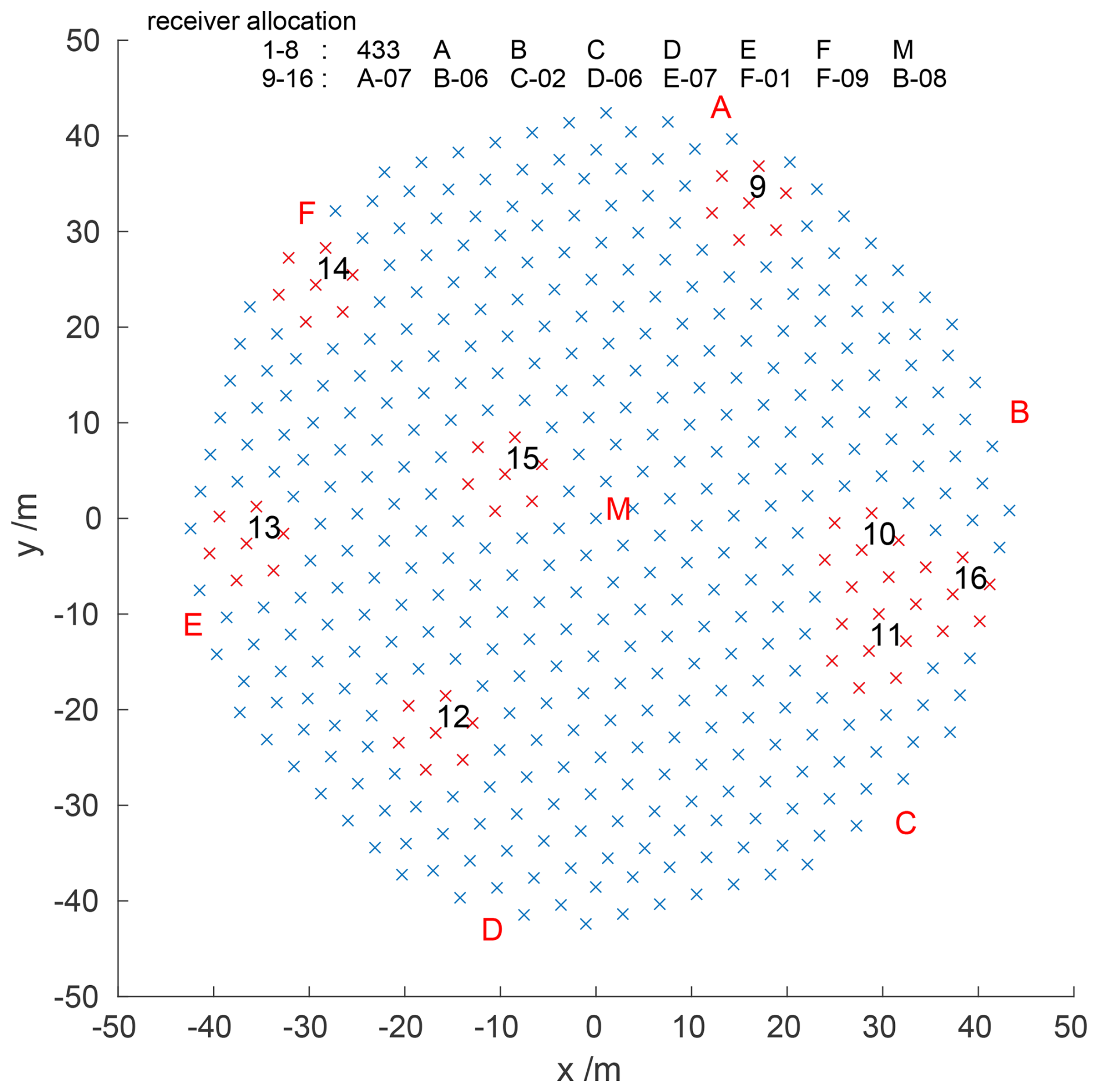
Figure 2Sketch of the MAARSY main antenna array, red sections and corresponding numbers mark some of the subarrays connected to receiver channel for the utilized experiment.
The receiving system consist of 16 channels, which can be connected to either the total main array or various subarrays inside or outside the main array through a selection and combining unit.
For MAARSY various experiments have been conducted during the initial years of the system to calibrate the receiving and transmitting part of the system. These experiments included hardware measurements of the coaxial antenna cables in amplitude and phase, injecting reference signals into the receiver to measure linearity and phase (Latteck et al., 2008). Furthermore, passive experiments were conducted employing radio astronomy methods to verify the beam pointing and beam width (Renkwitz et al., 2012, 2013).
Additional information about the transmit and receive pattern were gained with active radar experiments analyzing the backscatter of a sounding rocket payload and the locations of meteor head echoes (Renkwitz et al., 2015, 2017).
The MAARSY receiver phase calibration using the galactic radio source Cassiopeia A has been performed frequently (Chau et al., 2014) and since a few years it's derived every day, when the radio source drifts through the oblique beam (ϕ=180°, θ=10.5°) of the standard atmospheric monitoring experiment. Other active experiments exploiting reflections off the moon and satellites turned out to have too large uncertainties.
The limitations of these experiments are, that the passive radio astronomy experiments basically can only conducted for southern directions due to the polar location of the radar. The active experiment are either rarely done towards only one major direction (sounding rocket trajectory) and for the meteor head echoes only the vertical beam pointing has been used.
2.2 SIMONe Norway – previous calibrations
SIMONe Norway is a multi-static coded continuous wave meteor radar network operating at 32.55 MHz and as a wide field of view instrument it's covering about 500 km radius from its center. On the transmit site six 2-element crossed yagi antennas emit individual orthogonal codes, while only one of the eight receiving sites of the network use a five antenna interferometer of 3-element crossed yagi antennas. The receiving sites used in this study (near Stø and Saura) are single-antenna site, which means that the transmitters are used to derive angle-of-departure estimates to determine the target positions. These estimates require accurate knowledge of the relative phases of the transmitted signals. More details are provided in Huyghebaert et al. (2022).
The phase calibration of SIMONe interferometers, in this case the transmitting site, follows the empirical approach of Chau and Clahsen (2019). This method derives the relative phase offsets directly from specular meteor echo data by applying beamforming and least-squares fitting to the complex spatial coherences of selected echoes. It first performs a relative calibration using suitable meteor events and then refines the absolute phases through optimization constrained by the expected angular and altitude distributions of specular meteor echoes.
2.3 Saura – previous calibrations
The Saura partial reflection radar (PRR) is operated at 3.17 MHz and thus is sensible to gradients in the electron density allowing partial reflection from the lowermost part of the ionosphere (Singer et al., 2008). With its rather large antenna array (Fig. 3) and individual transceiver modules per antenna Doppler Beam Steering experiments are conducted. These measurements are mostly meant for deriving horizontal and vertical winds and the vertical electron density profile utilizing both magneto-ionic polarisations (Renkwitz et al., 2018, 2023).
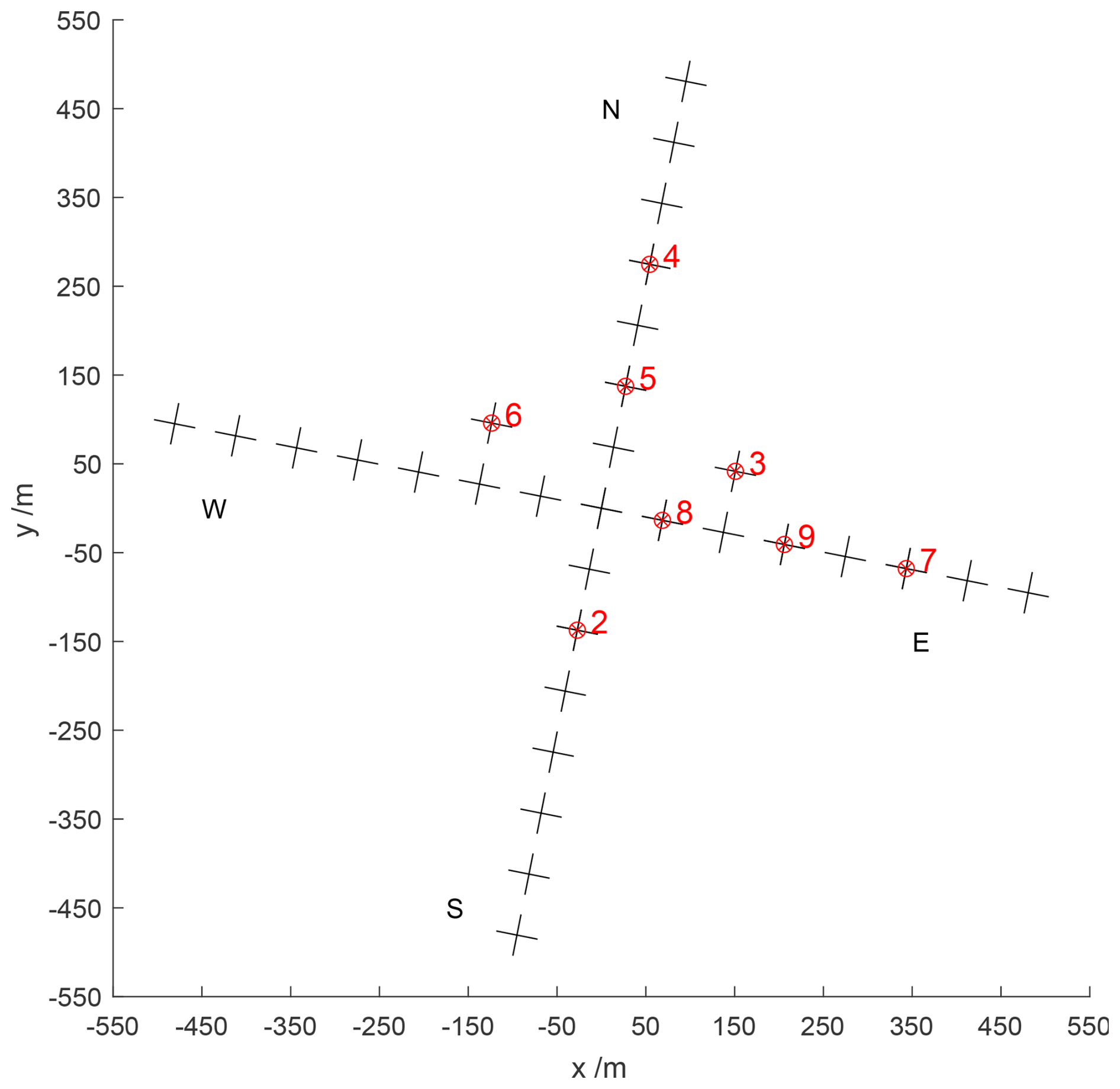
Figure 3Sketch of the Saura radar antenna array, marked antennas are connected to individual receiver channels used for interferometric AoA solutions.
A calibration of that radar is basically limited to a few hardware measurements, specifically for the range and phase of the individual receiver channel by injecting a known signal into the antenna ports. These tests revealed no significant phase offset for the current Saura receiving system. Therefore the larger uncertainty lies with the coaxial cables and the antennas.
The phases of the coaxial cable cannot be measured easily as they are connected to each dipole antenna feed at about 10 m above ground. However, they have been phased matched when the radar was installed in 2002. One good indication of proper functionality, except atmospheric radar returns, are measurements of s21 parameter with a network analyzer between adjacent antennas. With that an isolation of approximately −35 dB for directly neighboring antennas and about another 10 dB to the second next were found, which indicates a generally good condition. At the same time a mean phase offset of 96.3° was measurable for adjacent antennas across the array, which corresponds quite nicely to the free-space assumption
where ψc represents the coupling phase, dsp and λ the spacing distance of the antennas and the wavelength, both in unit m. Deviations below 10° could be found and are used as reference for future comparisons. The simulation of the antenna coupling by using e.g. Numerical Electromagnetics Code (NEC) or other appropriate tools is certainly useful, but even without this relative information is gained given the very regular arrangement of the antenna array.
For a presumably reliable phase calibration of the receiving system we, however, applied an empirical and iterative process using interferometric AoA-positions to solve the 2π ambiguity resulting from the widely spaced antenna array (980 m each axis, equivalent to almost 10.5 λ). For that, we assume that the derived median AoA-positions of the ionospheric return for a period of e.g. one month do not vary much. Thus, for the vertical beam pointing experiment the corresponding AoA-position should be found for any combinations of the receiving antennas at zenith. For the four off-vertical positions, symmetric AoA-positions near the nominal beam pointing directions need to be found. The statistical locations of the scattering D region structures are shown in Fig. 3 of Renkwitz et al. (2018). Starting with e.g. the smallest triangle (receiver 3, 8, 9) for the largest unambiguous angular coverage, receiver phases are optimized for the expected positions. Iteratively, the other possible receiver combinations are used to optimize their phases.
A limitation of this method is, that phases are only derived for the antennas that are connected to the receivers and with that eight out of 31, while the first channel is connected to the hardware combined array of 29 antennas. Thus, all other antennas would need to be connected to the receivers for a sufficient amount of time, even though these would not be specifically useful for the scientific mission.
The detected echo power of MAARSY for vertical beam pointing employing the entire antenna array for transmit and receive during six hours around the HELIX passage are depicted in Fig. 4. The received echoes from HELIX are favorably placed in between the maximum range (basically the height) of the lower stratosphere and the lower ranges of the Polar Mesosphere Summer Echoes (PMSE).
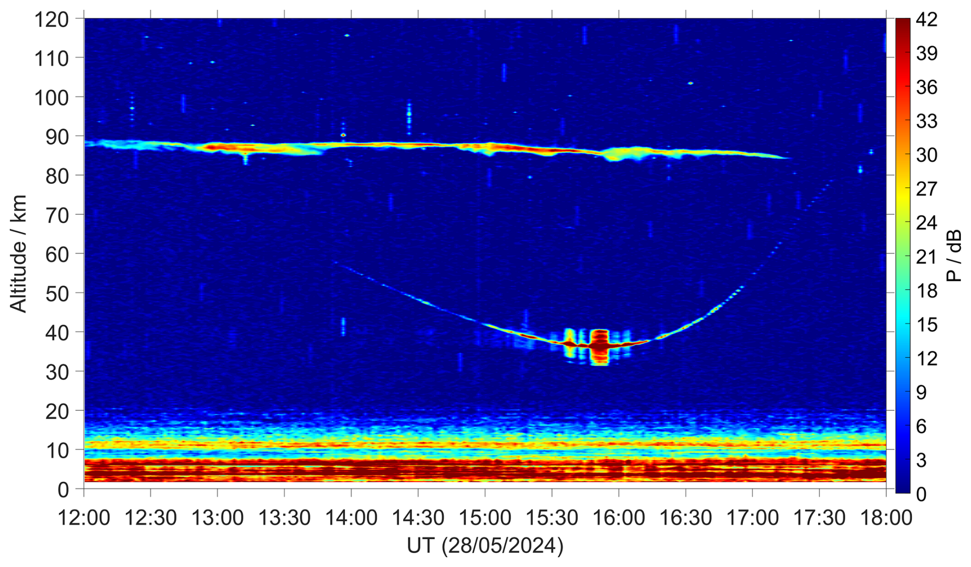
Figure 4Echo strength recorded by MAARSY on 28 May 2024. The trail of HELIX is clearly visible between 30 and 60 km range below a polar mesospheric summer echo at 88 km altitude and above the tropospheric echoes.
The radar typically conducts experiments with a limited number of beam pointing directions to maintain a good temporal resolution. Outside a dedicated campaign, typical experiments are conducted with vertical beam pointing for the mesosphere or a five beam pointing direction scanning mode, simultaneously monitoring from the troposphere to the mesosphere.
For this study the five beam scanning experiment is exploited in order to maximize the chances matching the transmit beam main and sidelobes to the HELIX trajectory.
3.1 Receiver phase calibration of MAARSY knowing the position of the scattering target
Even though MAARSY is regularly calibrated by galactic noise sources, predominantly the supernova remnant Cassiopeia A, we aimed for applying the same concept on the HELIX balloon. The passive receiving system phase calibration of MAARSY has been described in Chau et al. (2014) and is typically performed for the culmination at ϕ=180° and θ=10.5°. For our resolution this source can be treated as a point target at infinity distance and for a given time it is located at the directions cosines θx and θy. The expected phase difference at two antennas i and j is
where Δx, Δy, Δz represent the antenna spacings and λ the wavelength, both in m, and Δij is the phase offset.
Since a few years this beam pointing direction for Cassiopeia A is probed by a standard monitoring experiment and thus allows a daily median calibration phase. Knowing the position of the source, in this case the reflecting target, per time, we calculate the corresponding phases of the antenna array subarrays connected to the individual receiver channel (Eq. 2). Comparing the simulated and measured phase offsets between subarrays enables the derivation of initially unknown phases, such as those of the internal system and antenna contributions.
For this active phase calibration with HELIX the time of its passage through the main beam and for vertical pointing direction was used to avoid ambiguities of phase wraps resulting into fringes and radiation pattern induced signal-to-noise ratio reduction. The comparison of the passive phase calibration using Cassiopeia A and the active HELIX calibration is shown in Fig. 5 for all 16 receiver channel.
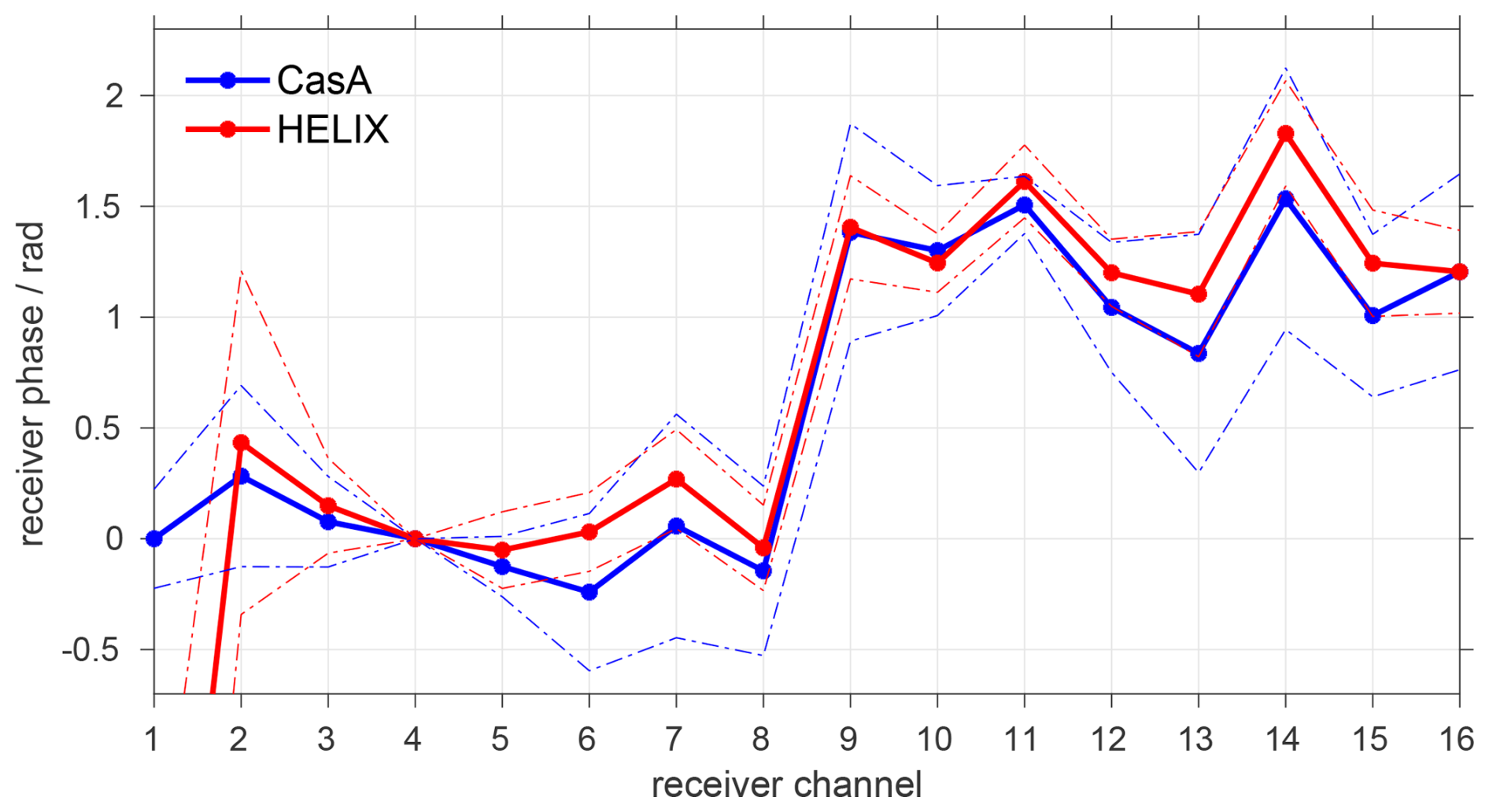
Figure 5Derived MAARSY receiver phases for two independent experiments, multi-month estimates using Cassiopeia A radio source (blue) and from backscatter of HELIX flyover (red). Broken lines represent the corresponding standard deviation.
3.2 AoA comparison with trajectory – Saura
In this section we present the derived target positions for the Saura PRR applying the assumed receiver phases. These phases have been empirically estimated by measurements of the antenna array and coaxial cable network and statistical AoA positions.
We applied the estimated phases to solve for multiple simultaneous targets using the MUSIC algorithm (Schmidt, 1986). Given the partly large baselines, multiple AoA solutions are possible due to unknown number of phase wraps (2π ambiguity). As the position of the balloon is known by the GNSS track, we restrict the AoA solutions around the known position at the time. The estimated AoA positions of HELIX are shown in Fig. 6 depicted in directional cosines of spherical coordinates for both polarisations used by Saura and the superimposed GNSS track. The same AoA positions and HELIX GNSS track are shown in Fig. 7, but shown in color-coded altitude over latitude and longitude. The derived AoA positions within θ<60° match the GNSS track quite nicely, however the estimated altitudes partly differ by 500 m, which is actually below the range resolution of the radar experiment. The 60° zenith angle field of view are circumscribed by the maximum possible range to the target as above 80 km range the ionospheric echoes superseded.
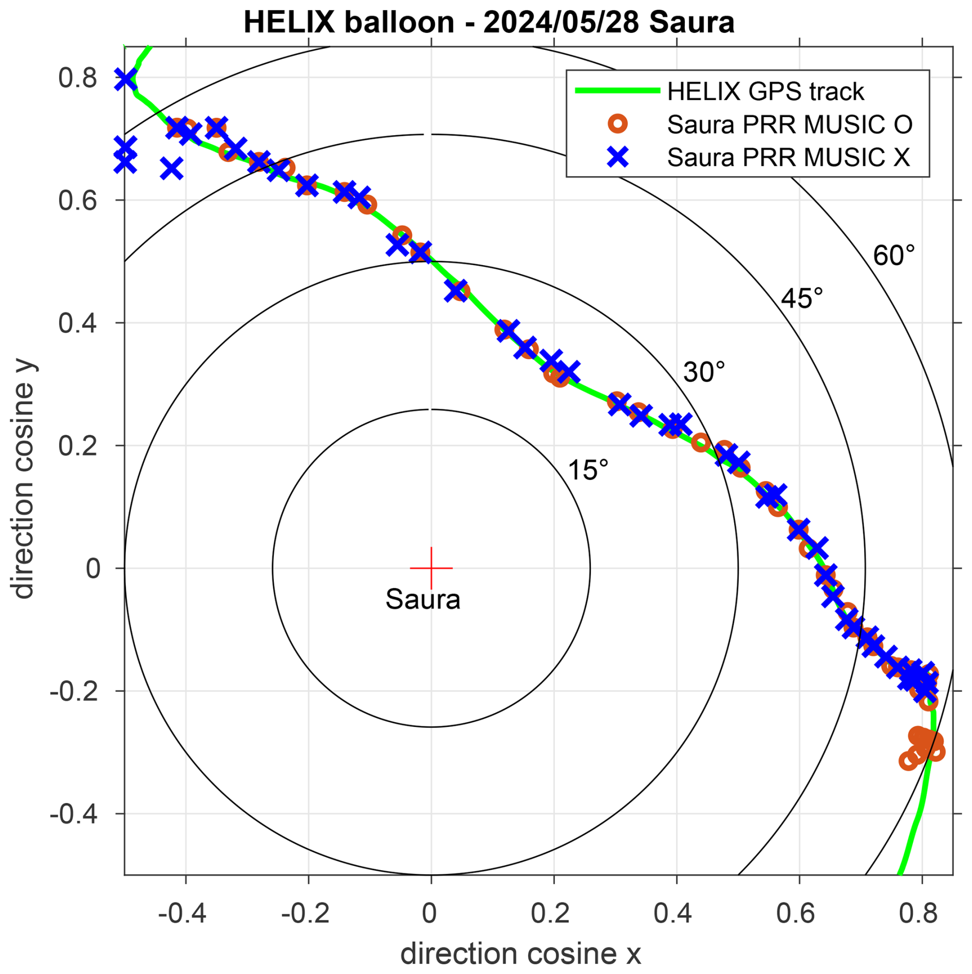
Figure 6Helix trajectory (green) superimposed with the derived MUSIC positions for O- and X-mode of Saura with corresponding symbols.
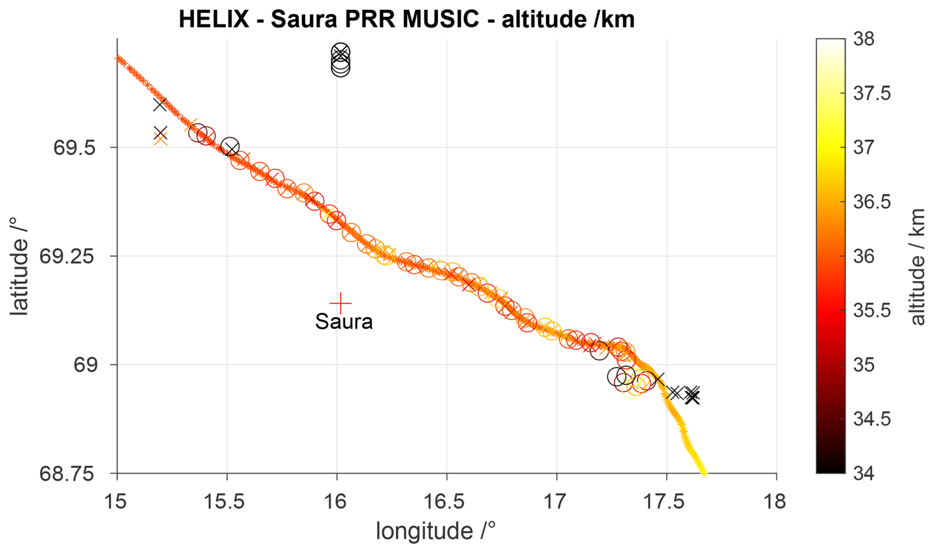
Figure 7Trajectory of HELIX (dots) superimposed by derived AoA positions for Saura using MUSIC (O and X symbols for corresponding magneto-ionic mode), color-coded are the altitudes for both.
3.3 AoA comparison with trajectory – MAARSY
In the case of MAARSY, both plain AoA solutions with only three subarray groups as well as MUSIC have been tested with a different number of receiver channel. In the simplest case, receivers 10, 11 and 16 (see Fig. 2) are assigned to the closely spaced subarrays B-06, C-02 and B-08, respectively, to estimate positions as these offer the largest angular unambiguity. Here we only solved for one dominant position for each experiment runtime of 48 s. The found positions agreed well to the HELIX trajectory, however, by this test we only verified the plausibility of these three estimated receiver phases. AoA positions using all eight equivalent subarrays (channel 9–16) at once without considering 2π ambiguities results into alias positions within the unambiguous angular ranges. Without any previous knowledge one needs to test various possible phase wraps for each subarray to find the most likely AoA position based on the phase residuals.
Another efficient method to solve for multi channel AoA positions is MUSIC as we have applied it already to the Saura PRR data for the same purpose. We tested MUSIC using seven of the larger subarray groups (A–F, M) as well as the eight smallest subarray groups and using the 15 receiver channel altogether. The latter turned out to show the largest errors in the estimated positions, which we attribute to the redundancy and mutual dependency of quite some of the smallest subarrays from the larger patches, as they are actually a part of it. Furthermore the quite different beamwidths of 31° instead of 11° and the corresponding nulls in the subarray pattern will have an impact. The derived locations of HELIX using MUSIC with eight groups of seven antennas each are depicted in Fig. 8, with color-coded range to both the HELIX trajectory and the estimated positions.
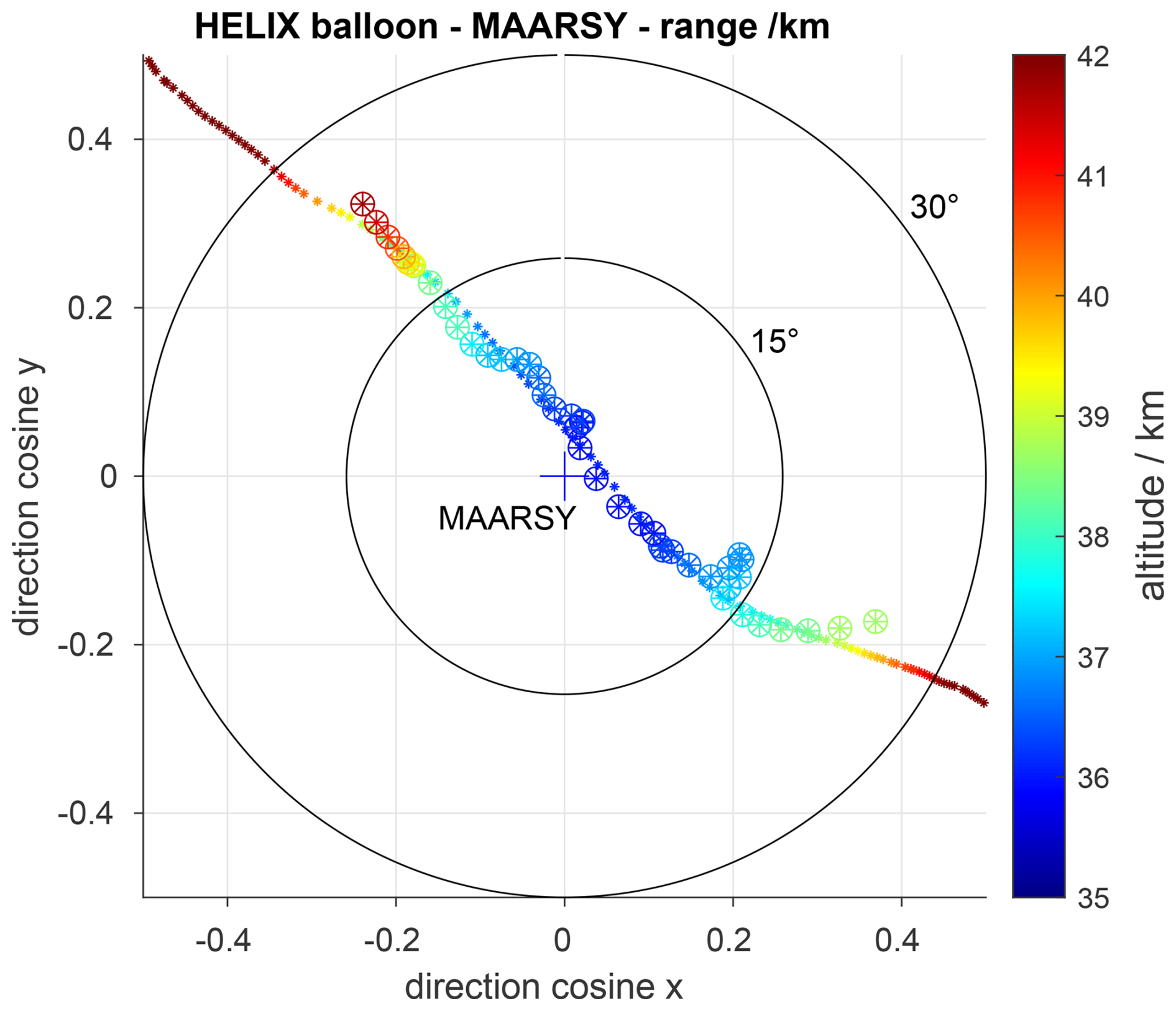
Figure 8Trajectory of HELIX converted to spherical coordinates at MAARSY location superimposed by the derived MUSIC positions using eight hexagon-shaped subarray groups.
3.4 AoA comparison with trajectory – SIMONe Norway
In principle the SIMONe system represents an all-sky instrument as basically individual antennas with little directivity are used for the transmission site. This configuration offers a large angular field of view, which is also visible in the detected HELIX radar echoes and thus AoA positions covering a distance of up to 100 km into southeastern direction during its approach. The derived HELIX locations for Stø overlaid with the GNSS positions are depicted in Fig. 9, where the positions are obtained using an approach similar to the beamforming and nonlinear least-squares method applied in the specular meteor analysis described by Chau and Clahsen (2019). In this case, however, the cross-spectra between the antennas are used instead of the complex spatial coherences.
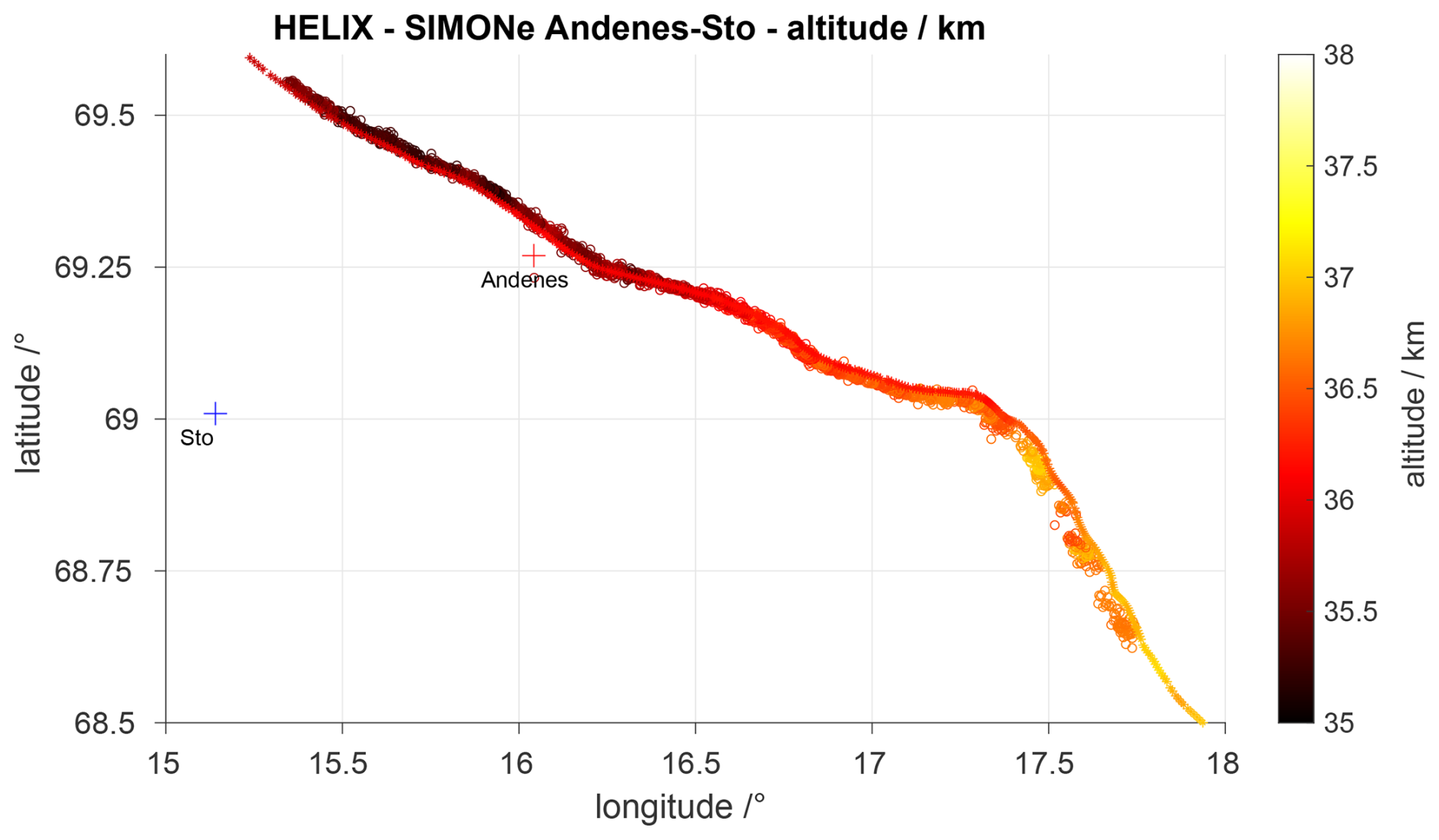
Figure 9Trajectory of HELIX over geographical coordinates superimposed by the derived AoA positions for the SIMONe Norway Andenes-Stø link. Both radar sites are indicated.
This field of view is supported by the open fjord waters in that direction in contrast to the 45 km towards northwest, where at the transmit site for this direction the lower elevation angles are blocked by hills with a peak height of about 400 m a.s.l.
Equivalent results with even a bit less scatter were also derived for the SIMONe receiver located at Saura, near the Saura PRR radar site. For the other locations of the network the coverage was partly significantly reduced, caused by less favoured locations, namely reduced field of view, ambient noise and being at more remote locations and thus also having a significantly different incident angle to HELIX than the transmitter site.
3.5 Comparison of simulated radiation pattern and detected echo power
In this section we aim to compare the simulated radiation pattern of the radar with the detected echo power for individual beam pointing directions.
In the case of Saura, HELIX was drifting through the dominant sidelobes, which are caused by the sparsely populated Mills-cross antenna array configuration (see Fig. 3). The transmission radiation pattern is calculated purely on the geometry, specifically the antenna locations and thus the array factor, and assuming a cos 3(θ) pattern for the individual dipoles. Note, the antenna dipoles are mounted above a typically rather watery soil and this assumption might still be too tentative. To estimate the variability of the received echo power for a single receiver and thus antenna, the superposition of the transmission pattern and another dipole pattern is used to calculate the required two-way intensities (see Fig. 10). The detected as well as the simulated intensities for the five beam pointing directions over time are depicted in Fig. 11. Note, the shown detected power represents the median of the receiver channels that have been used previously for the direction finding interferometry for each experiment runtime of 220 s, basically still representing a single dipole on reception.
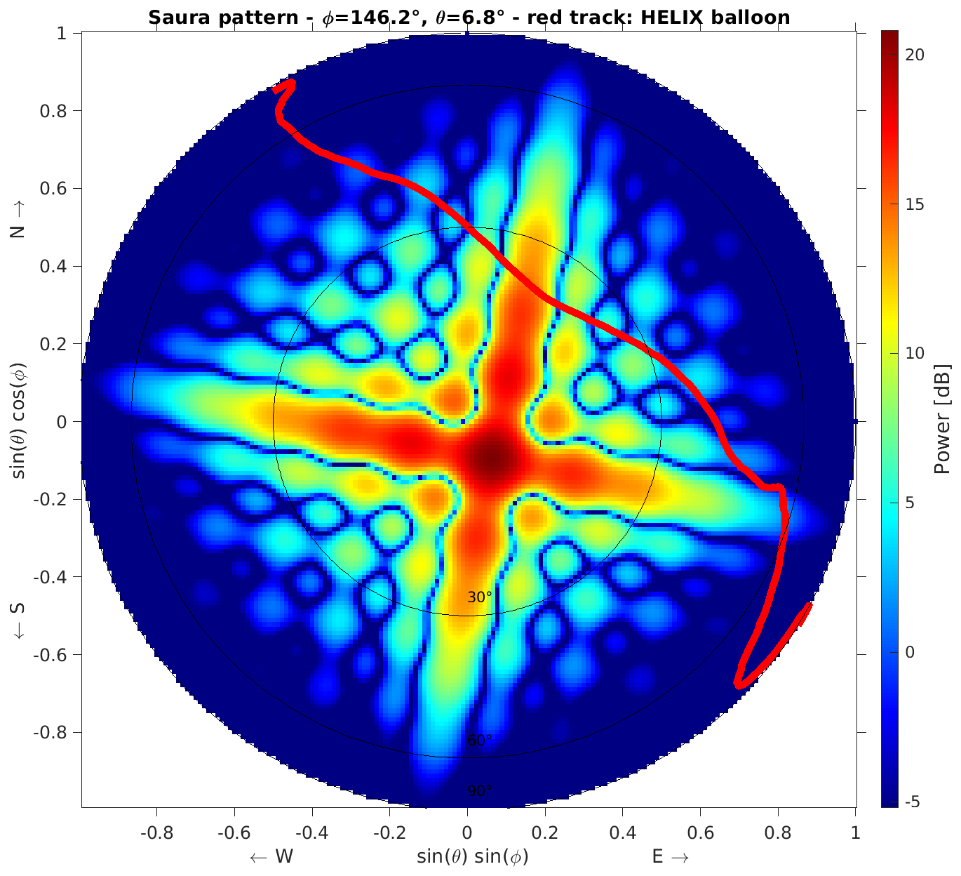
Figure 10Simulated two-way radiation pattern of Saura with beam pointing to southeastern position superimposed with the HELIX trajectory.
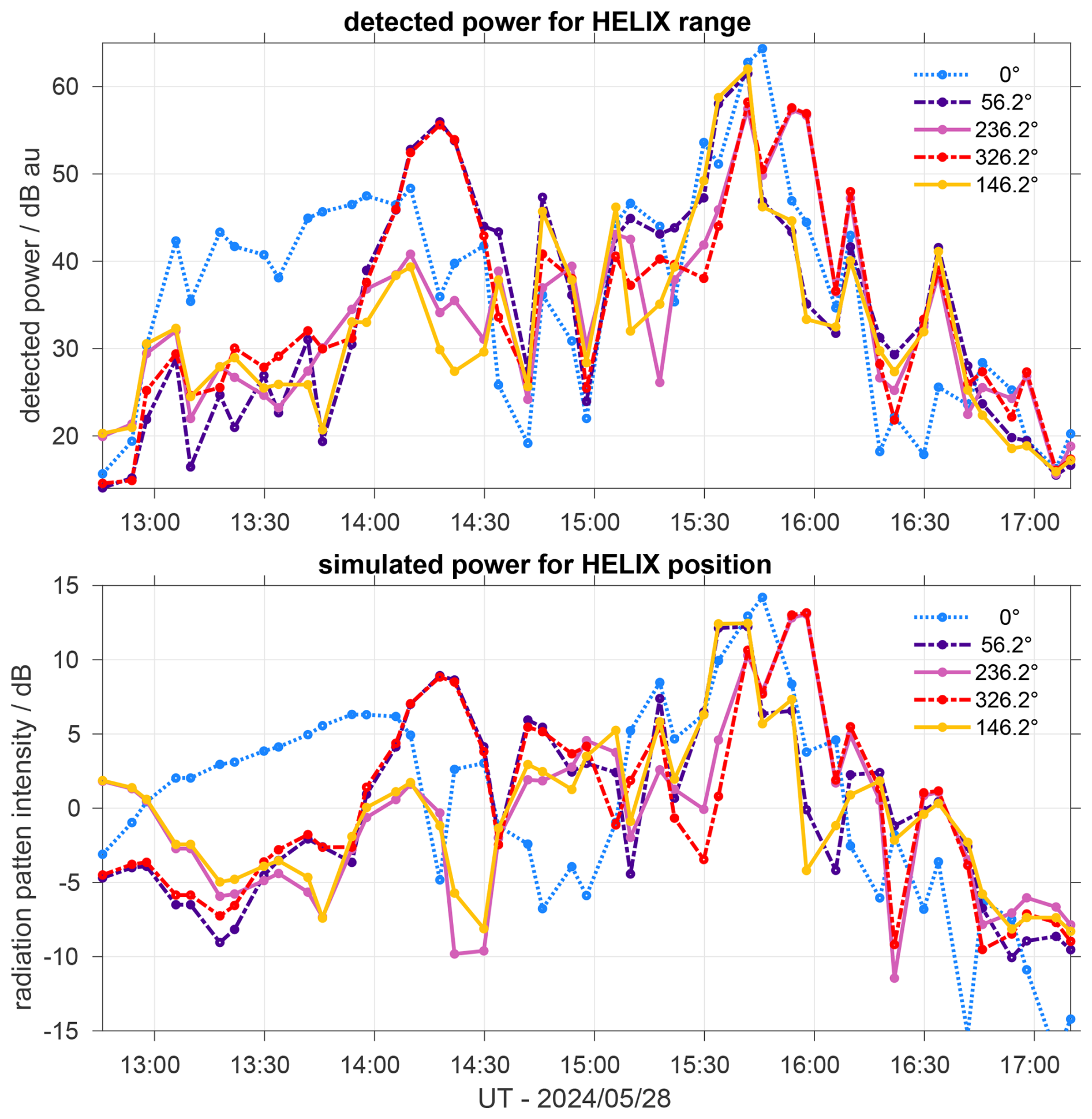
Figure 11Detected power along for the individual beam pointing directions of Saura and nominal range to HELIX (upper panel) and the predicted power from the simulated radiation pattern.
The same methodology of comparing the detected echo power with the simulated radiation pattern was also used for MAARSY. For this radar system multiple options exist as MAARSY receiver channels are typically connected to different sizes of patches (subarrays) distributed within or outside the main antenna array. Here, we present the results for subarrays of 49 antennas (called anemone), which are formed out of seven hexagon-shaped groups with each seven antennas that represent the smallest available subarrays.
The simulated vertical beam pointing radiation pattern for MAARSY using the entire antenna array (433 elements) for transmission and a 49 element subarray on reception is depicted in Fig. 12. For this simulation we again calculate the array factor based on the array geometry and approximate the pattern of the individual array element by a cos (θ)4 pattern to maintain a realistic suppression off boresight pointing (−3 and −10 dB at 38 and 65°, respectively).
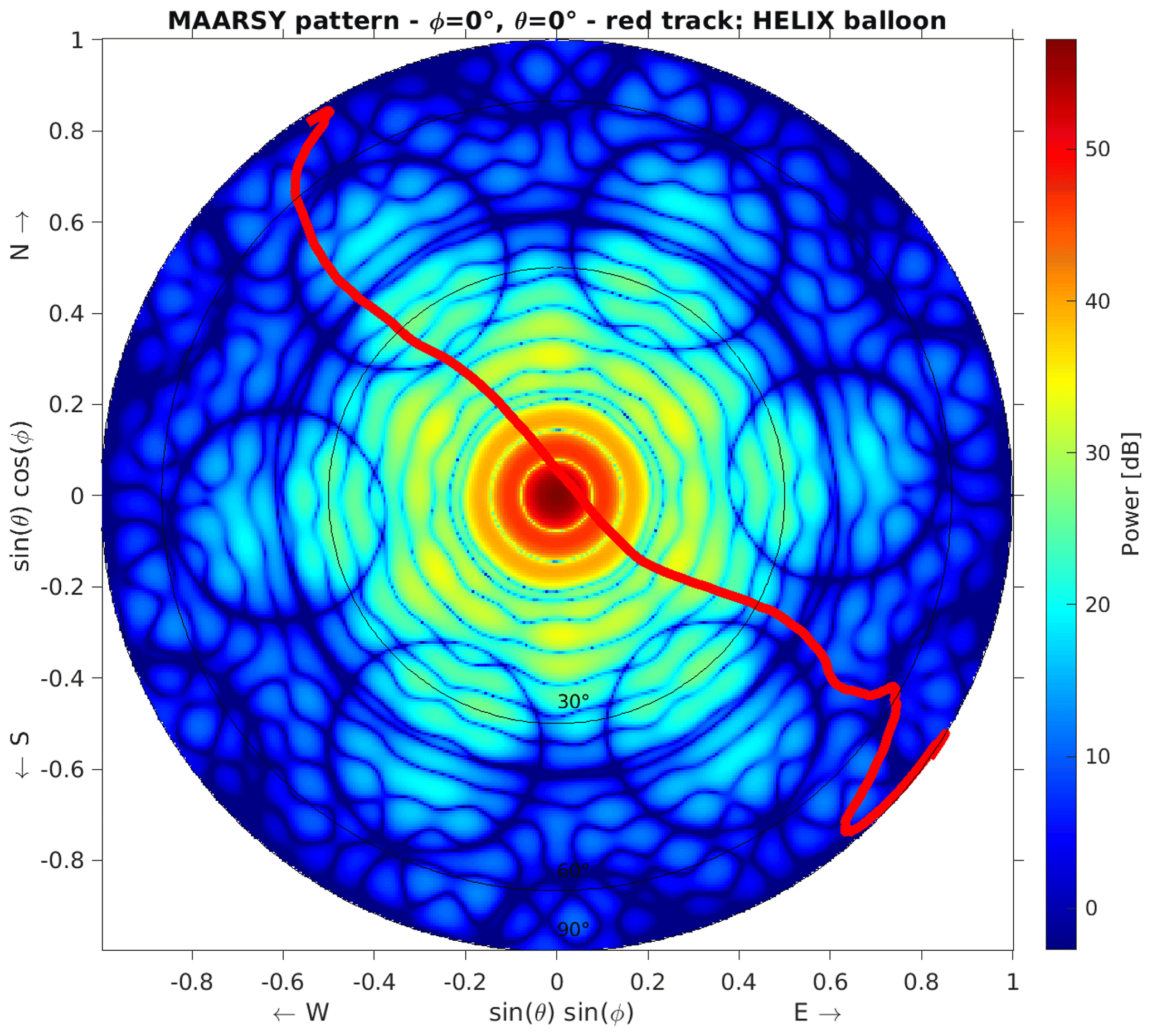
Figure 12MAARSY two-way vertical beam pointing radiation pattern using the entire antenna array on transmission and a 49 antenna subarray on reception. The red track represents the HELIX trajectory.
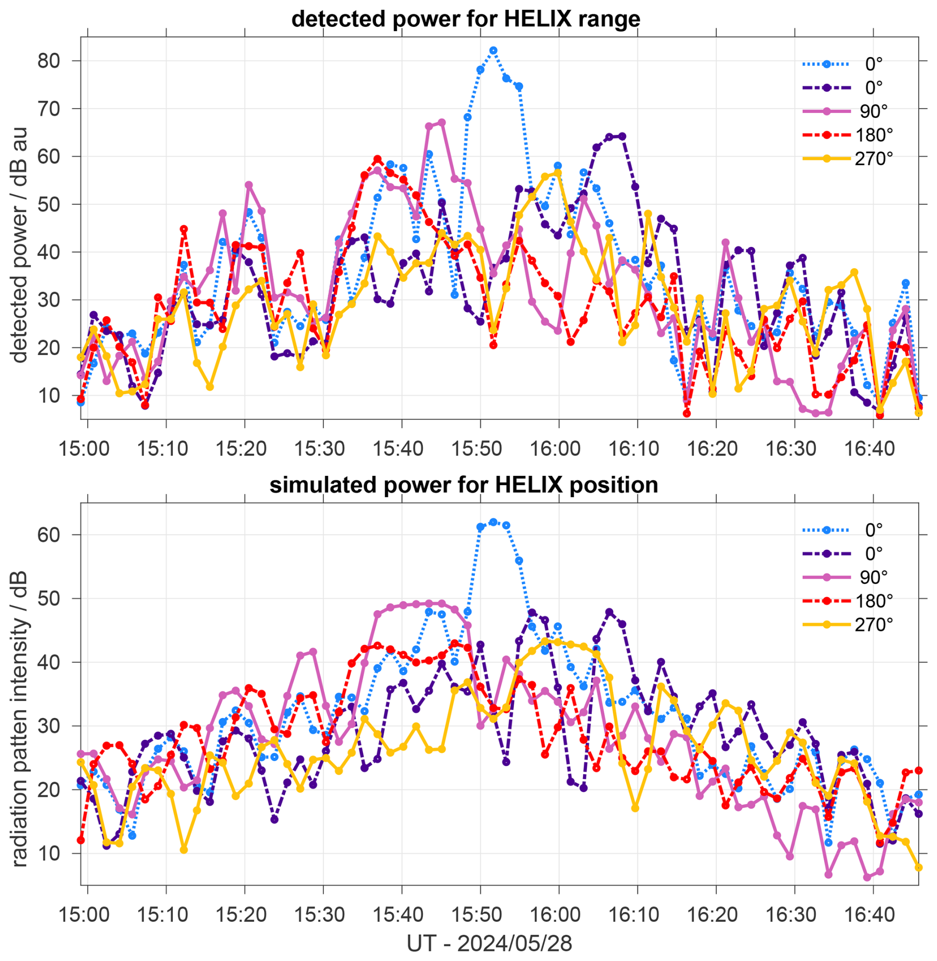
Contrary to the situation for Saura, HELIX was actually passing through MAARSY's mainbeam lobe as well as basically all concentric sidelobes. This symmetry is also visible for the simulated and detected power in Fig. 13 for the vertical beam pointing.
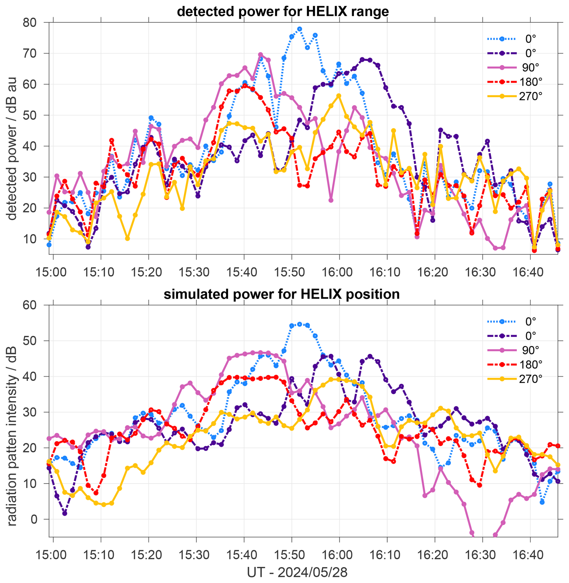
Figure 13Equivalent to Fig. 11, comparison of detected power at MAARSY 49 element array (top) and the predicted power from the simulated radiation pattern.
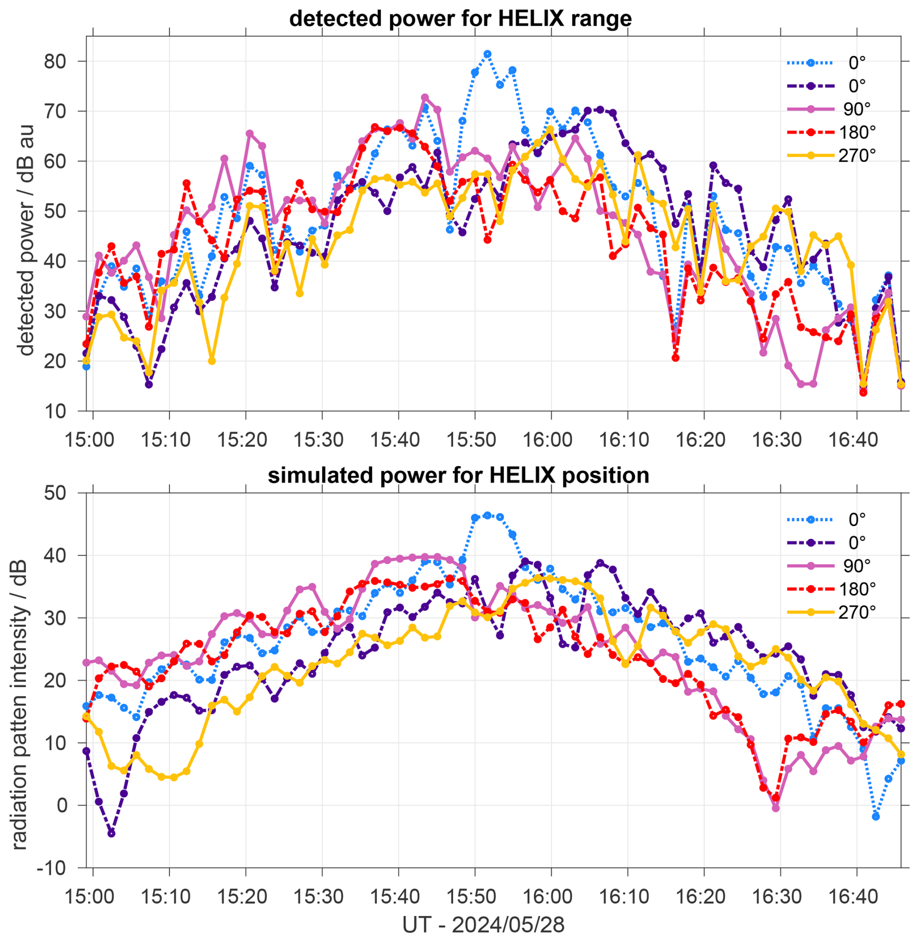
Complementary, the results for the entire main antenna array and for the smallest subarray of seven antennas on reception are shown in the Appendix (Figs. A1 and A2).
The MAARSY receiver phases derived from the active HELIX experiment partly differ from those of the regularly conducted passive experiment (Fig. 5). The largest deviation are in the order of 0.25 rad, e.g. for receiver number 7. The estimated values from the active experiment are, however, within the statistical uncertainty of the passive experiment. Note, the phases of the passive experiment are typically averaged for weeks or even months to reduce the uncertainty. A larger variability of phase estimates is regularly seen for the passive CasA calibrations with standard deviation of up to 35° even for multiple consecutive days. This spread was interpreted as being caused by both internal and external effects. Internal effects might be individual misbehaving, e.g. not properly initialized or synchronized, receiver modules, which might occur for individual or multiple modules for one experiment run. External effects for the observed phase variability origin from ionospheric effects like scintillations or from changes of the antenna array properties. The antenna array properties may be modified by weather, covering parts of the antenna array elements and the soil by water, snow and ice. These variations will also affect the coupling of the antennas and thus the phase center of the subarrays forming the receiver channel.
Seeing a much reduced variability of estimated phases for HELIX suggests that the internal effects are less important than external ionospheric effects as for the HELIX experiment no ionospheric wave propagation was involved.
The derived AoA MUSIC positions of the Saura PRR matched nicely the HELIX GNSS track of both polarisations, up to off-vertical angles of about 55° (Fig. 6). An equivalently good agreement was visible for the derived altitudes with errors less than the radar range resolution (Fig. 7). Beyond the zenith angle of 55° (69° N, 17.5° E; ≈ 62 km distance for the approach) the estimates deviate substantially. This is caused by the angular attenuation given by the radiation pattern, but more importantly the presence of the lower ionosphere. Partial reflection echoes start to be seen from about 60 km altitude and thus mask the rather faint oblique HELIX signal by that time.
For MAARSY, the derived MUSIC positions of HELIX seem to scatter around the nominal GNSS track (Fig. 8) for locations near the main beam pointing direction but also within the sidelobes. The shown results origins from using eight hexagon-shaped groups (each seven antennas) distributed over the array. In principle the same behavior was also found for using seven large subarrays of each 49 antennas representing the majority of the antennas array, however, here the reduced beam width limited the angular visibility of the HELIX echoes. Already the most simplest interferometry attempt, using only three nearby small subarrays have shown the same variability. At this point we speculate that the observed variability of the AoA positions is caused by the angular dependency of radar cross-section and the superposition of the many individual scattering structures of HELIX, the balloon coated with radar reflective sheet, the multiform payload and the harness between both. Note the radar wavelength of 5.6 m that roughly matches the size of the payload structure and the rather nicely shaped balloon of about 106 m3 volume. Nevertheless most of the derived AoA positions match well to the GNSS track confirming the previous phase calibration.
For SIMONe we focussed on two receiving locations, which have shown the best coverage of HELIX because of their favorable locations near the transmitter site and free line-of-sight to most of the trajectory. For both locations nearly 150 km coverage of the HELIX track was achieved and have been compared to the GNSS track (Fig. 9). The derived altitudes deviate to the GNSS track by less than the range resolution of the radar system, while the best match was found near the mid-point of the field of view. Besides that, a minor clockwise rotation of the derived positions (≈ 1°) is discernible, which might be caused by a possible imperfection of the known transmit antenna locations.
In summary of the previously discussed results we were able to derive reasonably accurate AoA positions for all three radar systems. Some of the observed inaccuracies were surprisingly found for the VHF radar, but for this wavelength HELIX certainly does not represent an ideal calibration target given its dimensions and multiform shape. To ascertain the correct detection of HELIX, giving its strong backscatter and thus the presence of clearly visible code sidelobes along the range sampling, we also compared the detected range with the calculated range to the GNSS positions. The largest range deviation to the calculated range to the GNSS track are equivalent to the range resolution and a median deviation of only 2 m was found (Fig. 14), which demonstrates a proper range calibration and detection of the target.
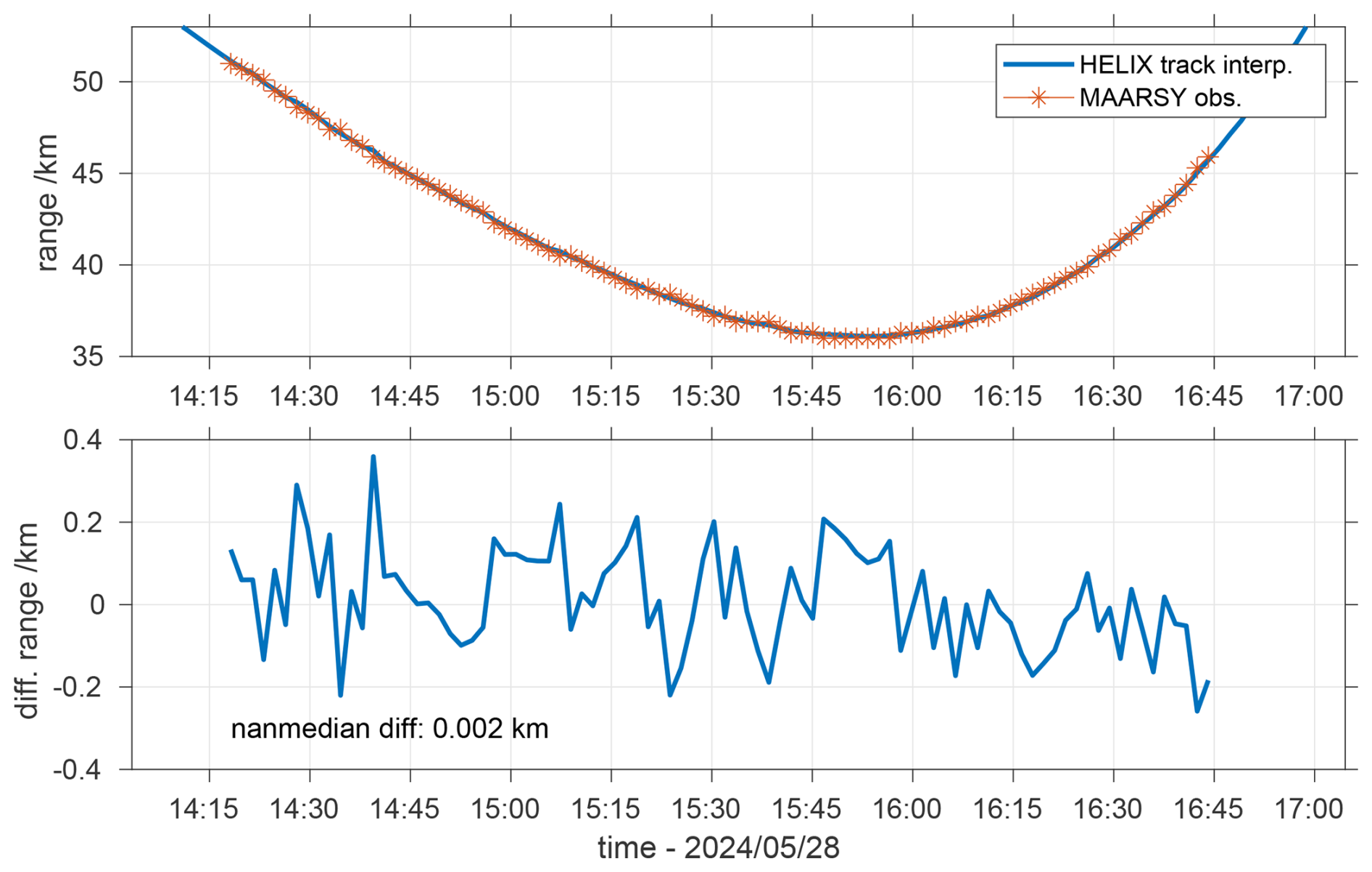
Figure 14MAARSY detected range vs. calculated range from the interpolated HELIX trajectory (upper panel) and the resulting differential range.
Subsequently we aimed for comparing the assumed radiation pattern of Saura and MAARSY with the detected echo power. Here we found an overall good agreement in the general evolution of the detected echo power and the simulated intensities (Figs. 11, 13). The timing of the relative enhancements of the detected power for the individual beam pointing directions when HELIX was crossing the side or even main lobes are very pronounced. This is particularly obvious for the major Saura sidelobes angularly spread beyond 45° zenith angle (Fig. 10). A detailed one-to-one comparison of the individual simulated sidelobes however show quite some variability, but it's not been the aim of this study to achieve a full sphere calibration of the radar. For this we would need to model the antenna arrays much more accurately including the actual antenna properties, soil conditions etc. and the mutual coupling between the antennas, whereas we only calculated the array factor based on the antenna center locations and assumed the radiation pattern of the individual antennas. The total dynamic of simulated and detected power differ most for Saura, where, on the one hand, the watery soil might have a much larger impact on the antenna radiation pattern than expected, and on the other hand, the angular dependence on the radar cross-section of HELIX for this low frequency might be quite substantial.
In this study, we present the calibration of three different co-located atmospheric radar systems covering the frequency range of 3 to 53.5 MHz by observing a stratospheric balloon and its payload. While for the VHF radar various calibration targets and methods are applicable, but especially for the vertical pointing 3.17 MHz Saura system the options are very limited, given its low frequency and thus required target size and distance. A favorable situation appeared when a stratospheric balloon and its payload fortuitously drifted near the radar locations. Given the proximity, and especially the size, of the balloon and the payload a sufficient signal-to-noise ratio (SNR) was also detected with Saura.
We thus exploited the datasets of these radars to solve for AoA positions and by that confirmed the correct receiver phases and performance of the radars. For most cases the derived AoA positions were nicely matching the GNSS track, however, the largest deviations were found either for low SNR scenarios, but also for MAARSY near the main beam and first sidelobe. A solid explanation for the latter could not be found, but we speculate that the individual multiform structures of the HELIX setup (balloon, payload and harness) introduced competitive superimposing signals.
The main findings of the experiment are:
-
Verification of earlier estimated or derived receiver phases by tracking HELIX for all three radars.
-
Detections of HELIX are according to the two-way radiation patterns of the individual radars.
-
Accordingly a maximum AoA coverage by SIMONe (θ=72.2°, ≈ 150 km), Saura (θ=56.1°, ≈ 120 km) and MAARSY (θ=22.3°, ≈ 40 km) was accomplished.
-
Observed deviations of the derived altitudes of the AoA positions were typically within the range resolution of the radars.
-
For SIMONe a clockwise rotation of ≈ 1° in the AoA positons was found, likely attributed to inaccuracy in the known transmit antenna locations.
-
Active phase calibration experiment with MAARSY confirmed the receiving phases previously derived from passive experiments as well as proper transmit beamforming.
-
A comparison of simulated backscatter intensities and detected radar echoes for Saura and MAARSY was performed to confirm the general radiation pattern, and more specifically, the distribution and intensity of the main and side lobes.
Considering the raised speculations about the VHF scattering at the multiform of HELIX more advanced methods such as imaging should help to eventually separate individual targets.
Since the HELIX mission, there have been seen at least two more balloon missions within the visibility of the radars, but they were practically at too large distances to be a suitable calibration target. Knowing about comparable missions in the future and having access to their live GNSS locations would enable one to set up specific experiments to steer the radar beam into favourable nearby positions. For example, this could be used for a symmetric drift scan.
The data needed to reproduce the figures including the observations is shared through https://www.radar-service.eu (last access: 2 March 2026) including DOI: https://doi.org/10.22000/ksbh1xe0bg3rn15k (Renkwitz, 2026) – Files are MATLAB data files.
TR and RL had the main responsibility of the radar experiments. The radar data analysis was mostly done by TR and MC. All authors contributed to the writing of the article and preparation of figures. All authors have read, corrected and agreed to the submitted version of the manuscript.
The contact author has declared that none of the authors has any competing interests.
Publisher's note: Copernicus Publications remains neutral with regard to jurisdictional claims made in the text, published maps, institutional affiliations, or any other geographical representation in this paper. The authors bear the ultimate responsibility for providing appropriate place names. Views expressed in the text are those of the authors and do not necessarily reflect the views of the publisher.
We like to acknowledge Scott Wakely of the University of Chicago for providing the GNSS track and details about the construction of the HELIX setup and mission. We furthermore appreciate the discussions with Jorge L. Chau, specifically the different AOA approaches, and thank Nico Pfeffer, Jens Wedrich and Thomas Barth for their help in maintaining the radar systems.
This paper was edited by Marco Milla and reviewed by two anonymous referees.
Bernhardt, P. A., Siefring, C. L., Thomason, J. F., Rodriquez, S. P., Nicholas, A. C., Koss, S. M., Nurnberger, M., Hoberman, C., Davis, M., Hysell, D. L., and Kelley, M. C.: Design and applications of a versatile HF radar calibration target in low Earth orbit, Radio Sci., 43, 1–23, https://doi.org/10.1029/2007RS003692, 2008. a, b
Chau, J. L. and Clahsen, M.: Empirical Phase Calibration for Multistatic Specular Meteor Radars Using a Beamforming Approach, Radio Sci., 54, 60–71, https://doi.org/10.1029/2018RS006741, 2019. a, b
Chau, J. L., Hysell, D. L., Kuyeng, K. M., and Galindo, F. R.: Phase calibration approaches for radar interferometry and imaging configurations: equatorial spread F results, Ann. Geophys., 26, 2333–2343, https://doi.org/10.5194/angeo-26-2333-2008, 2008. a
Chau, J. L., Renkwitz, T., Stober, G., and Latteck, R.: MAARSY multiple receiver phase calibration using radio sources, J. Atmos. Sol.-Terr. Phy. 118, 55–63, https://doi.org/10.1016/j.jastp.2013.04.004, 2014. a, b
From, W. R. and Whitehead, J. D.: The calibration of an HF Radar used for ionospheric research, Radio Sci., 19, 423–428, https://doi.org/10.1029/RS019i001p00423, 1984. a
Gao, B. and Mathews, J. D.: Phase and pattern calibration of the Jicamarca Radio Observatory radar using satellites, Mon. Not. R. Astron. Soc., 446, 3416–3426, https://doi.org/10.1093/mnras/stu2177, 2014. a
Ghosh, P., Renkwitz, T., Holt, L., Tsutsumi, M., Latteck, R., and Chau, J. L.: Intermittency of Waves in the Polar Upper Troposphere and Lower Stratosphere Over Northern Norway Using MAARSY, J. Geophys. Res.-Atmos., 129, https://doi.org/10.1029/2024JD040938, 2024. a
HELIX Collaboration, Coutu, S., Allison, P. S., Baiocchi, M., Beatty, J. J., Beaufore, L., Calderon, D. H., Castano, A. G., Chen, Y., Green, N., Hanna, D., Jeon, H. B., Klein, S. B., Kunkler, B., Lang, M., Mbarek, R., McBride, K., Mognet, S. I., Musser, J., Nutter, S., OBrien, S., Park, N., Powledge, K. M., Sakai, K., Tabata, M., Tarle, G., Tuttle, J. M., Visser, G., Wakely, S. P., and Yu, M.: The High Energy Light Isotope eXperiment program of direct cosmic-ray studies, arXiv [preprint], https://doi.org/10.48550/arXiv.2312.06796, 2023. a
Holdsworth, D. A., Tsutsumi, M., Reid, I. M., Nakamura, T., and Tsuda, T.: Interferometric meteor radar phase calibration using meteor echoes, Radio Sci., 39, https://doi.org/10.1029/2003RS003026, 2004. a
Huyghebaert, D., Clahsen, M., Chau, J. L., Renkwitz, T., Latteck, R., Johnsen, M. G., and Vierinen, J.: Multiple E-Region Radar Propagation Modes Measured by the VHF SIMONe Norway System During Active Ionospheric Conditions, Frontiers in Astronomy and Space Sciences, 9, 2022, https://doi.org/10.3389/fspas.2022.886037, 2022. a
Huyghebaert, D., Vierinen, J., Kero, J., Mann, I., Latteck, R., Kastinen, D., Våden, S., and Chau, J. L.: Examining the altitude dependence of meteor head echo plasma distributions with EISCAT and MAARSY, Adv. Space Res., 76, 2280–2294, https://doi.org/10.1016/j.asr.2025.06.056, 2025. a
Latteck, R., Singer, W., Morris, R. J., Hocking, W. K., Murphy, D. J., Holdsworth, D. A., and Swarnalingam, N.: Similarities and differences in polar mesosphere summer echoes observed in the Arctic and Antarctica, Ann. Geophys., 26, 2795–2806, https://doi.org/10.5194/angeo-26-2795-2008, 2008. a
Latteck, R., Singer, W., Rapp, M., Vandepeer, B., Renkwitz, T., Zecha, M., and Stober, G.: MAARSY – The new MST radar on Andøya: System description and first results, Radio Sci., 47, RS1006, https://doi.org/10.1029/2011RS004775, 2012. a
Latteck, R., Renkwitz, T., and Chau, J. L.: Two decades of long-term observations of polar mesospheric echoes at 69° N, J. Atmos. Sol.-Terr. Ph., 105576, https://doi.org/10.1016/j.jastp.2021.105576, 2021. a, b
Mathews, J. D., Breakall, J. K., and Sulzer, M. P.: The Moon as a calibration target of convenience for VHF-UHF radar systems, Radio Sci., 23, 1–12, https://doi.org/10.1029/RS023i001p00001, 1988. a
Palmer, R. D., Vangal, S., Larsen, M. F., Fukao, S., Nakamura, T., and Yamamoto, M.: Phase calibration of VHF spatial interferometry radars using stellar sources, Radio Sci., 31, 147–156, https://doi.org/10.1029/95RS02319, 1996. a
Ponomarenko, P., St.-Maurice, J.-P., and McWilliams, K. A.: Calibrating HF Radar Elevation Angle Measurements Using E Layer Backscatter Echoes, Radio Sci., 53, 1438–1449, https://doi.org/10.1029/2018RS006638, 2018. a
Renkwitz, T.: RenkwitzAMT2026, Leibniz Institute of Atmospheric Physics at the University of Rostock [data set], https://doi.org/10.22000/ksbh1xe0bg3rn15k, 2026. a
Renkwitz, T., Singer, W., Latteck, R., Stober, G., and Rapp, M.: Validation of the radiation pattern of the Middle Atmosphere Alomar Radar System (MAARSY), Adv. Radio Sci., 10, 245–253, https://doi.org/10.5194/ars-10-245-2012, 2012. a
Renkwitz, T., Stober, G., Latteck, R., Singer, W., and Rapp, M.: New experiments to validate the radiation pattern of the Middle Atmosphere Alomar Radar System (MAARSY), Adv. Radio Sci., 11, 283–289, https://doi.org/10.5194/ars-11-283-2013, 2013. a
Renkwitz, T., Schult, C., Latteck, R., and Stober, G.: Validation of the radiation pattern of the VHF MST radar MAARSY by scattering off a sounding rocket's payload, Adv. Radio Sci., 13, 41–48, https://doi.org/10.5194/ars-13-41-2015, 2015. a
Renkwitz, T., Schult, C., and Latteck, R.: VHF antenna pattern characterization by the observation of meteor head echoes, Atmos. Meas. Tech., 10, 527–535, https://doi.org/10.5194/amt-10-527-2017, 2017. a
Renkwitz, T., Tsutsumi, M., Laskar, F. I., Chau, J. L., and Latteck, R.: On the role of anisotropic MF/HF scattering in mesospheric wind estimation, Earth Planets Space, 70, 158, https://doi.org/10.1186/s40623-018-0927-0, 2018. a, b
Renkwitz, T., Sivakandan, M., Jaen, J., and Singer, W.: Ground-based noontime D-region electron density climatology over northern Norway, Atmos. Chem. Phys., 23, 10823–10834, https://doi.org/10.5194/acp-23-10823-2023, 2023. a
Schmidt, R. O.: Multiple Emitter Location and Signal Parameter Estimation, IEEE T. Antenn. Propag., 34, 276–280, 1986. a
Schult, C., Kero, J., Stober, G., and Brown, P.: Dual frequency measurements of meteor head echoes simultaneously detected with the MAARSY and EISCAT radar systems, Icarus, 355, 114137, https://doi.org/10.1016/j.icarus.2020.114137, 2021. a
Singer, W., Latteck, R., and Holdsworth, D. A.: A new narrow beam Doppler radar at 3 MHz for studies of the high-latitude middle atmosphere, Adv. Space Res., 41, 1488–1494, https://doi.org/10.1016/j.asr.2007.10.006, 2008. a
Spargo, A. J.: Radar Measurements of Gravitiy Wave Characteristics in the MLT, Master of philosophy, The University of Adelaide, South Australia, https://doi.org/10.4225/55/59015b841b883, 2016. a
StratoCat: Balloon launches – HELIX, https://stratocat.com.ar/fichas-e/2024/KRN-20240528.htm (last access: 2 March 2026), 2023. a
Tsutsumi, M., Holdsworth, D., Nakamura, T., and Reid, I.: Meteor observations with an MF radar, Earth Planets Space, 51, 691–699, https://doi.org/10.1186/BF03353227, 1999. a
Urco, J. M., Chau, J. L., Weber, T., and Latteck, R.: Enhancing the spatiotemporal features of polar mesosphere summer echoes using coherent MIMO and radar imaging at MAARSY, Atmos. Meas. Tech., 12, 955–969, https://doi.org/10.5194/amt-12-955-2019, 2019. a
Wan, B., Wu, X., Yue, X., Zhang, L., and Wang, L.: Calibration of Phased-Array High-Frequency Radar on an Anchored Floating Platform, Remote Sens., 14, https://doi.org/10.3390/rs14092174, 2022. a