
the Creative Commons Attribution 4.0 License.
the Creative Commons Attribution 4.0 License.
 | 12 Nov 2026
The Heterodyne Wind Lidar Gadget HEDWIG for the German research aircraft HALO: instrument design, wind retrieval and first airborne observations
Benjamin Witschas

Elina Köster
Oliver Kleinert
Christian Lemmerz
Oliver Lux
Stephan Rahm
The HEterodyne Detection Wind lIdar Gadget (HEDWIG) is a new airborne Doppler wind lidar developed at the German Aerospace Center (DLR) for high-resolution observations of atmospheric wind profiles. The instrument operates at an eye-safe wavelength of 1617 nm. A newly developed double-wedge scanner provides rapid and flexible beam steering, enabling both conical scanning for horizontal wind retrieval and parallel nadir-pointing observations for direct measurements of the vertical wind component. The complete instrument, including laser transmitter, receiver, scanner, data acquisition system and wind retrieval chain, is described in detail. Particular emphasis is placed on the optical and mechanical design of the scanner, the synchronized data acquisition, as well as the retrieval algorithms for line-of-sight (LOS) Doppler velocities and atmospheric wind vectors.
The instrument was successfully deployed for the first time aboard the German research aircraft HALO during the North Atlantic Waveguide, Dry Intrusion and Downstream Impact Campaign (NAWDIC) in winter 2026. Surface-return analyses demonstrate a systematic wind speed error below 0.1 m s−1 and a random error of about 0.2 m s−1 for single LOS measurements under high-SNR conditions. First airborne observations further demonstrate the capability of HEDWIG to retrieve horizontal wind vectors together with high-resolution vertical wind profiles. The instrument therefore provides a unique observational capability for airborne studies of atmospheric dynamics as well as for satellite instrument validation as for instance the Doppler velocity products of the cloud profiling radar on EarthCARE, but also for future missions as WIVERN and Aeolus-2.
- Article
(5358 KB) - Full-text XML
- BibTeX
- EndNote


Wind is one of the most important state variables of the atmosphere and plays a central role in the transport of momentum, heat, moisture, aerosols, and trace gases. Accurate measurements of the three-dimensional wind field are therefore essential for improving numerical weather prediction, understanding atmospheric dynamics, and investigating a wide range of atmospheric processes such as convection, gravity waves, turbulence, and aerosol transport.
Conventional wind observations are primarily provided by radiosondes, ground-based remote sensing systems, aircraft in situ measurements, and satellite observations. These measurement techniques either provide limited spatial coverage, low temporal resolution, or require dedicated measurement infrastructure. In contrary, airborne Doppler wind lidars provide a unique capability by combining the high vertical resolution of remote sensing profiling techniques with the flexibility of aircraft deployment and enable high-resolution wind observations over remote regions, oceans, and complex terrain.
Since the first application of an airborne heterodyne detection scanning Doppler wind lidar back in 1999 (Reitebuch et al., 2001), such systems have become valuable research instruments for a broad range of atmospheric applications (Yew et al., 2025). They have been used to investigate boundary-layer processes (Gasch et al., 2023), gravity waves (Witschas et al., 2017), convection, and atmospheric transport, to measure clear-air turbulence form an aircraft (Hamada et al., 2020), as well as to support aircraft wake-vortex studies and numerical weather prediction impact studies (Weissmann and Cardinali, 2007). Furthermore, airborne Doppler wind lidars provide important validation data for satellite missions, such as ESA's Aeolus mission, (Witschas et al., 2020) and are an essential tool for the development of future spaceborne wind lidar concepts (Bedka et al., 2025).
The ability to remotely retrieve wind profiles from an aircraft, however, requires sophisticated instrument concepts. Compared to ground-based systems, airborne wind lidars must operate under challenging environmental conditions, including aircraft vibrations, temperature variations, and dynamic changes in platform attitude. Furthermore, the aircraft velocity introduces a large Doppler contribution to the received signal, which must be accurately corrected for a precise wind retrieval. Finally, flexible beam-steering and scanning strategies are required to retrieve the three-dimensional wind vector and to compensate for aircraft attitude variations which is of particular importance for vertical wind speed measurements. These requirements impose stringent constraints on the laser transmitter, optical design, scanner concept, and data acquisition system.
A key challenge in the design of an airborne heterodyne detection Doppler wind lidar is to provide sufficient sensitivity to retrieve wind profiles over long ranges and under conditions of weak aerosol backscatter while maintaining a high spatial resolution. A useful metric for comparing the transmitter performance of different coherent wind lidar systems is the transmitter figure of merit (FOM), 𝒯FOM, introduced by Henderson et al. (2022). It is proportional to the coherent-detection signal-to-noise ratio (SNR) and therefore provides a convenient measure of the capability of a lidar system to retrieve winds at large distances or in clean atmospheric conditions. It is defined as:
where M2 is the laser beam quality factor, Ep is the laser pulse energy in Joule, frep is the laser pulse repetition rate in Hertz, and τp is the laser pulse duration (full width at half maximum) in nanoseconds. The corresponding spatial pulse length in meters is obtained by converting τp from nanoseconds to seconds and multiplying it by the speed of light. The resulting physical resolution of the lidar measurements is finally half of the spatial pulse length. Further, the pulse-duration dependence in Eq. (1) is based on the assumption that the spectral width of the lidar signal is dominated by the spectral width of the transmitted laser pulse, which is approximately inversely proportional to the pulse duration for near-transform-limited pulses.
The exponent α takes into account the probability of a good signal-peak detection, Pg, and approaches zero as Pg approaches 100 %. For Pg = 50 %, α ≈ 0.215, whereas a more stringent detection probability of 90 % corresponds to α ≈ 0.13, as used in a recent study by Bedka et al. (2026). In this study, a detection probability of 50 % is assumed, yielding α = 0.215, and hence, Eq. (1) reduces to (Henderson et al., 2022):
Equation (2) illustrates that increasing the laser pulse repetition rate cannot fully compensate for a reduced laser pulse energy, because 𝒯FOM scales linearly with pulse energy but only weakly (by the square-root) with pulse repetition rate. Consequently, wind lidars with a high pulse repetition rate based on all-fiber-based laser transmitters, which are typically limited in pulse energy by stimulated Brillouin scattering, generally exhibit a lower 𝒯FOM than bulk-solid-state laser systems. Nevertheless, their compactness, robustness and low maintenance requirements make them highly attractive for applications requiring comparatively short measurement ranges, such as wind-energy and boundary-layer studies. To illustrate different wind lidar design approaches and their respective transmitter performance, Table 1 summarizes representative airborne heterodyne Doppler wind lidar systems together with their calculated transmitter FOM.
Gasch et al. (2025)Cézard et al. (2026)Henderson et al. (2022)Kavaya et al. (2014)Bedka et al. (2023, 2025)Hamada et al. (2020)Witschas et al. (2017)Table 1Comparison of representative airborne heterodyne Doppler wind lidar systems and their respective transmitter parameters together with the resulting transmitter figure of merit 𝒯FOM.

a As no performance values of the AIRflows transceiver published yet, typical values for similar transceiver types as for instance the Windcube 200 (Vasiljevic et al., 2016) are considered.
b The actual value is not provided, hence, a reasonable value is considered for calculating 𝒯FOM for further comparison.
A recent example using all-fiber-based lasers for an airborne wind lidar is the AIRflows system developed by KIT (Karlsruhe Institute of Technology), which employs five fixed line-of-sight (LOS) beams and demonstrates precise, highly resolved wind measurements within the planetary boundary layer despite the comparatively low transmitter FOM of about 𝒯FOM = 0.05 (Gasch et al., 2025). As there are no performance values of the AIRflows transceiver published yet, typical values for similar transceiver types as for instance the Windcube 200 (Vasiljevic et al., 2016) are considered.
Another promising all-fiber-based airborne system called LIVE (for Lidar Vent, french for Wind Lidar) was developed by ONERA (Augere et al., 2019). Using an amplifier stage based on a novel glass matrix fiber, they reached pulse energies of 0.42 mJ, a high repetition rate of 14 000 Hz and a laser pulse duration of 1 µs, leading to 𝒯FOM = 0.32. With this system, vertical profiles of horizontal wind were measured with high vertical (150 m) and horizontal (2.5 km) resolution over ranges up to 7.5 km.
With the long-term objective of demonstrating the feasibility of a spaceborne heterodyne wind lidar, NASA has been pursuing high-energy wind lidar technology for more than 2 decades. The development progressed from the DAWN instrument (Kavaya et al., 2014) to Wind-SP (Henderson et al., 2022; Yu et al., 2022) and most recently to the Aerosol Wind Profiler (AWP) (Bedka et al., 2023, 2025, 2026). These systems employed high pulse energies of 40 to 250 mJ and consequently achieved the highest transmitter FOM reported to date, ranging from 2.5 to 3.2 J ns0.285 (Table 1), thereby enabling excellent data coverage even under weak aerosol conditions.
The Japan Aerospace Exploration Agency (JAXA) developed an airborne heterodyne Doppler wind lidar with the primary objective of detecting clear-air turbulence (CAT) features ahead of aircraft. Based on measurements from 19 research flights, the system demonstrated the capability to characterize CAT-related wind fluctuations up to 10 km ahead of the aircraft (Hamada et al., 2020). With a pulse energy of 3.3 mJ and a repetition rate of 1000 Hz, the system achieved 𝒯FOM = 0.68 J ns0.285 (Table 1), which is lower than the values achieved by the high-energy NASA systems but sufficient for its dedicated application.
At DLR, an airborne wind lidar operating at 2 µm has been developed and regularly operated for more than 25 years (Witschas et al., 2023) on the DLR Falcon aircraft. The instrument has been successfully deployed in numerous airborne campaigns addressing aircraft wake vortices (Köpp et al., 2004), aerosol characterization (Chouza et al., 2015), gravity-wave dynamics (Witschas et al., 2017, 2023), Aeolus calibration and validation (Witschas et al., 2020, 2022), and numerical weather prediction studies (Weissmann and Cardinali, 2007; Schäfler et al., 2018, 2020). Despite its comparatively modest transmitter FOM of 0.22 J ns0.285 compared to the NASA instruments, the system demonstrated excellent measurement capability through optimized retrieval algorithms based on spectral accumulation (Smalikho, 2003).
Building on the experience gained during the operation of the airborne 2 µm Doppler wind lidar, DLR initiated the development of its successor HEDWIG (Heterodyne Detection Wind lidar Gadget) for operation aboard the German research aircraft HALO. The objective was not only to improve the transmitter performance but also to develop a compact, airworthy wind lidar with flexible beam steering, programmable scan strategies, and a compact and modern data-acquisition architecture. HEDWIG combines a laser transmitter providing pulse energies of 2.7 mJ at a repetition rate of 750 Hz with a fast double-wedge scanner, resulting in 𝒯FOM = 0.31 J ns0.285. While this value remains below the FOM achieved by the high-energy NASA systems, it represents an improvement of approximately 40 % compared to the previous 2 µm system. Furthermore, the newly developed scanner enables flexible and rapid beam steering, allowing optimized scan strategies and improved spatial resolution.
The HEDWIG system had its first deployment during the North Atlantic Waveguide, Dry Intrusion and Downstream Impact Campaign (NAWDIC) which took place in January and February 2026 in Ireland (https://www.nawdic.kit.edu, last access: 9 November 2026). Main goal of this international field campaign was the investigation of the role of the tropopause structure, jet streams and dry-intrusion airstreams in the development of high-impact weather in Europe (Quinting et al., 2026). Within this framework, HEDWIG was operated aboard the German research aircraft HALO to provide high resolution wind speed profiles. In the future, HEDWIG data is also foreseen to be combined with the data from the differential absorption and high-spectral-resolution lidar WALES (also aboard HALO) to derive water vapor fluxes.
In this paper, the instrumental design of the novel HEDWIG instrument is presented in Sect. 2, followed by a discussion of the measurement principle and retrieval algorithms in Sect. 3. A first performance assessment based on airborne measurements acquired during NAWDIC is presented.
An overview of the HEDWIG instrument consisting of the airborne transceiver unit including the telescope and double-wedge scanner with the dimension of about 350 mm × 400 mm × 900 mm (excluding seat-rail adapters) and a total weight of 81 kg (right), and the data acquisition rack with the dimension of 650 mm × 550 mm × 1637 mm and a total weight of 118 kg (left) is provided in Fig. 1. A schematic block diagram of the HEDWIG laser transceiver is shown in Fig. 2.

Figure 1Overview of the HEDWIG airborne Doppler wind lidar. The system consists of the airborne lidar unit (right), comprising the laser transceiver, telescope, and double-wedge scanner mounted on the aircraft seat rails, and the data acquisition rack (left), containing the control electronics, acquisition computer, global navigation satellite system (GNSS) receiver, cooling unit, power distribution and housekeeping electronics.
2.1 Transceiver unit
The laser transceiver is based on the previously (until the end of 2021) commercially available WTX WindTracer developed by Lockheed Martin Coherent Technologies (Gatt et al., 2015) and integrates both the pulsed transmitter and the heterodyne detection receiver within a common optical bench, providing a compact and mechanically robust architecture for airborne operation.
It comprises a single-frequency continuous-wave local oscillator (LO) that serves as the injection seeder for the slave oscillator (SO) and is additionally used as a local oscillator for the coherent heterodyne detection. The LO is realized as a distributed-feedback (DFB) laser diode with a narrow spectral linewidth, providing high heterodyne efficiency. A part of the LO radiation (Fig. 2, dark-blue line) is coupled into the SO via an acousto-optic modulator (AOM) that additionally acts as a Q-switch. When the AOM is switched on, the LO optical path is aligned to match the optical axis of the SO and thus enables adequate seeding. The AOM additionally introduces a frequency offset of approximately 135 MHz, allowing to determine the magnitude and sign of the atmospheric Doppler shift unambiguously.

Figure 2Simplified optical layout of the HEDWIG wind lidar, showing the transceiver unit, including the seed laser (LO), slave oscillator (SO), acousto-optical modulator (AOM), laser crystal (LC), resonator mirrors (RM), piezo-ceramic transducer (PZT), polarizing beam splitter (PBS), detectors for the reference (REF) and atmospheric (ATM) signals, a quarter-wave plate () and the beam-expanding telescope emitting the laser pulses via the double-wedge scanner. The acquisition chain is also shown, comprising the signal amplifier (AMP), housekeeping unit (HK), global navigation satellite system (GNSS) receiver, inertial reference system (IRS), and the double-wedge scanner, all connected to the data acquisition computer (DAQ).
The SO, with a resonator length of about 0.7 m, employs an Er:YAG laser crystal (LC) pumped by a fiber laser operating at 1532 nm. It emits laser pulses at 1617.25 nm (vacuum wavelength) with a pulse energy of approximately 2.7 mJ and a pulse duration of 300 ns full width at half maximum (90 m pulse length). The pulse repetition frequency is adjustable between 500 and 999 Hz, with 750 Hz being used during normal operation, corresponding to an average transmitted power of approximately 2 W. The operating wavelength of 1617.25 nm lies within an atmospheric transmission window with only weak water-vapor absorption while fulfilling eye-safety requirements. Consequently, under favorable aerosol conditions, wind profiles can be retrieved throughout the troposphere. The comparatively high pulse repetition rate additionally enables efficient spectral accumulation during post-processing (Sect. 3), thereby reducing the impact of speckle noise. The emitted laser pulses exhibit nearly Gaussian spatial, temporal, and spectral characteristics (M2 = 1.2), reducing random and systematic uncertainties in the Doppler estimation. To ensure resonance between the SO cavity length and the LO radiation, the SO cavity length is controlled by the ramp and fire technique (Henderson et al., 1986), where the resonance signal is monitored by the reference detector (REF).
The transmitted and received optical paths are separated by a polarizing beam splitter (PBS), which simultaneously protects the sensitive receiver from the high-energy outgoing laser pulse. A quarter-wave plate () converts the laser beam to circular polarization, after which an on-axis telescope expands it to a diameter of approximately 11 cm. The beam then enters the double-wedge scanner, which enables arbitrary beam steering (see Sect. 2.2). Prior to entering the atmosphere, the beam passes a 400 mm diameter 35.6 mm thick fused silica window with anti-reflection coatings on both sides (Layertec GmbH) that is mounted in the fuselage of the aircraft.
Atmospheric aerosols and cloud particles backscatter a fraction of the emitted laser pulse towards the lidar, where it is collected by the same telescope used for transmission. The backscattered light is reflected by the PBS and directed to the optical signal detector (ATM), where it is mixed with a portion of the LO laser. After pre-amplification directly at the detector, the analog detector signal is additionally amplified and digitized at a sampling frequency of 625 MHz with 8-bit resolution, and continuously stored on a dedicated solid-state drive for subsequent post-processing for every single laser shot with a pulse repetition frequency of 750 Hz (see Sect. 2.3).
2.2 Double-wedge scanner unit
To retrieve the three-dimensional (3D) wind vector using the velocity–azimuth display (VAD) technique (Browning and Wexler, 1968), the laser beam must be steered away from nadir and directed successively towards different azimuth angles. HEDWIG employs a double-wedge scanner for this purpose (Amirault and DiMarzio, 1985), providing rapid and flexible beam steering while maintaining a compact optical layout suitable for airborne operation.
The scanner, developed and built at DLR, is primarily operated in two measurement modes. During standard wind-vector observations, the beam is steered along a conical scan with a constant off-nadir angle, typically 20°, while the azimuth angle is varied in a step and stare procedure. This measurement geometry forms the basis for the retrieval of the horizontal wind vector using the VAD technique described in Sect. 3. Owing to the high dynamic performance of the scanner, the conical scans are regularly intermitted by short nadir-pointing periods, during which vertical wind profiles are acquired with substantially higher temporal resolution compared to vertical velocities obtained from the VAD retrieval. The rapid transition between these scan modes of 0.1 to 0.2 s enables nearly simultaneous measurements of horizontal and vertical wind components without significantly reducing the sampling rate and precision of horizontal wind measurements. This transition time is more than five times shorter than that of the 2 µm DWL, which used a belt drive motor and required approximately one second to switch between off-nadir and nadir pointing directions.
The scanner consists of two identical optical wedges with a diameter of 160 mm, mounted in independently rotatable hollow-shaft direct-drive motors. They have a wedge angle of 6° and are manufactured from silicon (Laser Components Germany GmbH), which provides a refractive index of approximately 3.45 at the operating wavelength of 1617 nm. This enables a large beam deflection with a comparatively small wedge angle and therefore allows a compact scanner design. In contrast to a single rotating wedge, which produces a conical scan with a fixed opening angle, the independent rotation of two wedges enables arbitrary beam directions. For HEDWIG, every pointing direction inside the scan cone with a half-cone angle of 30° can be reached by selecting an appropriate combination of wedge rotation angles as it is shown by the scanner principle sketch in Fig. 3.

Figure 3Principle sketch of the HEDWIG double-wedge scanner. The expanded laser beam (red) is successively refracted by two independently rotatable silicon wedges (6° each) separated by a 10 mm air gap, resulting in a maximum off-nadir pointing angle of approximately 30°. Each wedge is actuated by a hollow-shaft torque motor and equipped with a high-resolution optical encoder.
The scanner concept follows the optical principle introduced for the previous DLR 2 µm wind lidar, but was redesigned for improved mechanical stability, dynamic performance and integration aboard HALO. The two wedges are mounted coaxially with a small air gap of ≈ 10 mm between them, allowing the expanded laser beam to pass through the complete scanner aperture without vignetting. The wedge motors are independently controlled by DC-powered drives (Copley Controls, Accelnet ADP-055-18) via a CAN-bus interface.
Accurate beam pointing is essential for Doppler wind lidar measurements, particularly at ranges of several kilometres where small angular errors translate into substantial spatial offsets. Each wedge is actuated by a direct-drive hollow-shaft torque motor (MACCON, MF0255005-X0X) equipped with a high-resolution optical angular encoder (Renishaw Signum Interface). The direct-drive concept avoids mechanical transmission elements such as gearboxes or timing belts, eliminating backlash and transmission errors while providing high positioning dynamics and virtually maintenance-free operation. The encoder rings provide 144 000 counts per revolution, corresponding to an angular resolution of approximately 9 arcsec, which results in a pointing uncertainty that is negligible compared to the atmospheric sampling volume.
The scanner also enables active compensation of aircraft attitude variations during flight. The desired LOS direction is defined in a local geographic coordinate system, whereas the scanner is fixed to the aircraft frame. Therefore, variations in aircraft roll, pitch and heading are compensated actively by adapting the wedge positions using the aircraft inertial reference system (IRS), with an update rate of 1 Hz. This capability allows the laser beam to maintain a stable nadir direction even under dynamic flight conditions, enabling direct and high-resolution measurements of the vertical wind component.
2.3 Data acquisition
The HEDWIG data acquisition system, developed and built at DLR, comprises the laser transceiver electronics and laser cooling unit, a global navigation satellite system (GNSS) receiver, a PXI Express (PXIe) computer for data acquisition, a keyboard and monitor for instrument control, and a housekeeping (HK) unit responsible for time synchronization of all system components. These units are integrated into a single instrument rack, shown in Fig. 1 (left).
The central component of the DAQ system is an 8-slot PXIe chassis (Schroff), which digitizes the atmospheric return signal for every transmitted laser pulse while simultaneously recording all auxiliary information required for the wind retrieval. These include the aircraft position, velocity and attitude, as well as the scanner position and corresponding laser beam pointing direction. The PXIe system consists of (1) a PXIe embedded controller (NI-8881), (2) a high-speed digitizer (NI-5162), (3) a two-channel oscilloscope (NI-5110), (4) a timing and counter card with oven-controlled oscillator (NI-6614), (5) an ARINC-429 acquisition card (Condor, CEI-620), (6) a dual-port RS-232 interface (NI-8432/2), and (7) a solid-state storage device (Conduant, DM-U.2).
The digitizer is used to sample the reference and the atmospheric signal with 625 MHz and 8-bit resolution using typically 62 500 samples, corresponding to an acquisition time of ts = 100 µs and a sampling range rs = km, which is principally sufficient for maximum flight altitude of ≈ 14.1 km, considering an off-nadir angle of 20°. In rare occasions where HALO is flying above 13 km, the acquisition length is extended to 75 000 samples to keep a larger amount of signal sampled range below the surface return, which is used for noise correction. For dedicated high spectral resolution measurements (Chouza et al., 2017), the sampling rate can be increased to 2.5 GHz. The raw data for each single pulse is stored on a solid-state-disc. Prior to storage, a header containing the corresponding HK information, i.e. the aircraft position, velocity and attitude, as well as a time stamp used for synchronization is appended to each single-shot record. The single-shot data storage leads to a data rate of about 30 MB s−1, and provides maximum flexibility for the data post processing, as for instance the exclusion of bad laser pulses before accumulation and the correction of laser frequency variations from pulse to pulse.
Accurate synchronization between all recorded quantities is essential for the subsequent wind retrieval and is realized with the NI-6614 timing card. In particular, the 10 MHz clock signal from the oven-controlled oscillator that is mounted on the timing card is fed into one channel of the NI-6614 card where it is pre-scaled by a factor of 100 to generate a 100 kHz clock signal. The 100 kHz (10 µs) resolution provides a sufficiently high accuracy and enables the counter (32 bit unsigned integer) to continuously count up to almost 12 h, which is longer than the maximum flight duration.
The 100 kHz timing signal is synchronized to the pulse-per-second (PPS) signal provided by the GNSS receiver (Septentrio, PolaRx4), which additionally provides the aircraft position and velocity. Accurate aircraft velocity measurements are essential because the aircraft motion (typically about 200 m s−1) dominates the measured Doppler shift and must therefore be corrected by means of the wind retrieval algorithm. The accuracy of the horizontal velocity measured with the GNSS receiver is specified to be 1.5 × 10⁻³ m s−1. The data provided by the GNSS module is acquired by using one slot of the RS-232 module (NI-8432/2).
Besides the aircraft velocity, precise knowledge of the aircraft attitude is equally essential for accurate wind retrieval. For this purpose, roll, pitch and yaw angles are measured by an inertial reference system (IRS, IGI, AEROcontrol III) and acquired via the ARINC-429 acquisition card (Condor, CEI-620). The specified accuracy of the roll and pitch angles is 0.003° (Giez et al., 2023). In addition, the angular positions of the two scanner wedges are continuously acquired via the CAN-bus interface from the motor controllers. Together with the aircraft attitude information, these encoder measurements allow the instantaneous laser beam pointing direction to be determined in an Earth-referenced coordinate system and provide the input for the active attitude compensation of the scanner (Sect. 2.2).
The two-channel oscilloscope (NI-5110) continuously monitors the laser ramp and fire signals, providing a convenient diagnostic of the laser performance during operation. Deviations from the nominal behavior can immediately be identified and compensated by adjusting relevant laser parameters, such as the pump power or temperature set points.
The principal specifications of the HEDWIG system are summarized in Table 2.
Table 2Principal specifications of the HEDWIG airborne Doppler wind lidar.

* FWHM denotes the full width at half maximum.
The HEDWIG system measures the Doppler frequency shift of laser radiation backscattered by atmospheric aerosols, providing the LOS component of the wind velocity. To retrieve the 3D wind vector of the sampled atmospheric volume, LOS measurements are acquired along different viewing directions, realized by means of the double-wedge scanner (Sect. 2.2).
The standard operating modes comprise (i) nadir-pointing measurements for the determination of the vertical wind component and (ii) conical scans for the retrieval of the horizontal wind vector using the VAD technique (Browning and Wexler, 1968; Smalikho, 2003). During conical scanning, the off-nadir angle, typically 20°, is kept constant while the azimuth angle is varied over 360°. Under the assumption of horizontally homogeneous flow within the sampled volume, the measured range-resolved LOS velocities follow a sinusoidal variation with azimuth angle, from which the horizontal wind speed and wind direction can be estimated as described in Sect. 3.2. Routine observations combine conical VAD scans with interleaved nadir-pointing measurements.
The complete HEDWIG wind retrieval consists of four consecutive processing steps. First, the power spectra from the recorded heterodyne signal for intervals that correspond to 100 m vertical resolution are calculated. Subsequently, the LOS wind speed is determined (Sect. 3.1). In a next step, the LOS velocity is corrected for aircraft motion and afterwards, the corrected LOS observations are transformed into the Earth-fixed reference frame. Finally, the atmospheric wind vector profile is retrieved, as explained in Sect. 3.1 and 3.2.
3.1 Retrieval of the line-of-sight Doppler velocity
For each transmitted laser pulse, the backscattered light is coherently mixed with a fraction of the LO serving as reference. Their interference at the photodetector produces an intermediate-frequency (IF) heterodyne signal whose frequency is directly related to the difference between the optical frequencies of the transmitted and received radiation. Since the emitted laser pulse is frequency shifted by the AOM, the sign of the Doppler shift is preserved and both positive and negative LOS velocities can be unambiguously determined.
The Doppler frequency is estimated from the power spectrum of the atmospheric heterodyne signal. Prior to spectral analysis, individual laser shots are filtered according to housekeeping parameters and reference pulse characteristics to exclude measurements affected by reduced laser performance or transient disturbances. For instance, if the beat frequency of the reference pulse differs by more than 10 % from the nominal AOM frequency of 135 MHz or the laser pulse buildup time is larger than 5.0 µs (default value is 3.5 µs), then the laser pulse is not considered for accumulation. During normal laser operation, only very few individual laser shots are excluded, whereas this fraction can increase to a few percent under disturbed laser operating conditions, for example at the beginning of a flight, when the laser has not yet reached full thermal stabilization. Moreover, before accumulating the respective reference pulse spectra, they are frequency shifted to a defined reference value of 135 MHz to correct for pulse-to-pulse frequency variations and thus to avoid spectral broadening in the accumulation process. The same frequency shift is subsequently applied to the atmospheric spectra. The detector raw signal containing the atmospheric return is divided into segments that lead to 100 m range gates in the vertical domain while considering the actual laser beam pointing angle, the aircraft altitude and attitude, and the reference pulse timing. Subsequently, the spectra of the remaining laser shots are incoherently accumulated to improve the SNR. Principally, the accumulation interval can be adapted to the measurement objective and atmospheric backscatter conditions, providing a flexible compromise between spatial resolution and velocity precision. The default accumulation interval for a single LOS measurement is 1 s.
Furthermore, the detector signal at the end of the record is used to analyze the detector noise characteristics, which is especially important in the low-signal regime (Frehlich et al., 1997; Beyon et al., 2012; Witschas et al., 2017). For airborne measurements, the signal following the ground/surface return contains only electronic chain (detector, amplifier, digitizer) noise and is therefore used to estimate the system noise characteristics. The power spectrum of the noise signal is calculated for each single laser pulse and additionally averaged over a certain period, typically 1 s. Consequently, each power spectrum for each single range gate is divided by the respective noise spectrum to correct for the system noise and the receiver frequency response.
After subtraction of the measured reference frequency, the remaining frequency shift ΔfD corresponds solely to the atmospheric Doppler velocity which is proportional to the LOS velocity vD according to ΔfD = , where f0 is the laser frequency, c is the velocity of light, and λ0 = = 1617.25 nm is the laser wavelength.
The derived vD still contains the Doppler contribution induced by the aircraft motion when projected onto the LOS direction vac, which has to be considered to get the actual wind induced Doppler velocity vLOS = vD − vac.
The resulting vLOS is initially referenced to the moving lidar instrument and has to be transformed into an Earth-fixed coordinate system. The transformation from the scanner coordinate system into the Earth-fixed frame is performed by applying the sequence of rotation matrices (see e.g., Koks, 2008). The resulting LOS vector accounts for the instantaneous aircraft attitude as well as the fixed mounting angles between the scanner and the aircraft reference frame. Consequently, every individual laser pulse is assigned an accurately georeferenced viewing direction.
For measurements with dedicated nadir-pointing during which the laser beam is aligned with the local vertical direction, vLOS equals the vertical wind speed. Unlike the retrieval of the horizontal wind vector from conical scans, no VAD inversion or averaging over multiple viewing directions is required. Consequently, the achievable temporal and vertical resolution is solely determined by the selected accumulation interval of the Doppler spectra.
3.2 Wind vector retrieval from conical scanning
The horizontal wind vector is retrieved from a sequence of LOS velocity measurements acquired during conical scanning. As summarized by Smalikho (2003), there are several techniques of wind vector estimation from wind lidar data. For HEDWIG, two different algorithms are applied and finally combined. The first approach uses an inversion algorithm, the second one is based on a signal accumulation method, the Maximum Function of Accumulated Spectra (MFAS) technique, as invented by Smalikho (2003). The inversion algorithm derives the wind vector from a certain number of off-nadir LOS measurement (e.g., 12), by calculating several independent wind-vector estimates from all possible triplets of LOS observations separated by ≈ 120°. Thus, depending on signal conditions, a maximum of e.g., = 4 wind vectors can be obtained for each scan, which are finally averaged to one wind vector per scan. During an iterative quality-control procedure, the wind in each LOS measurement result is compared to the expected wind from the average wind vector in the corresponding LOS direction and removed, if deviating more than e.g. 1 m s−1, before repeating the calculation of a subsequent average vector. The final averaged wind vector is reported as valid, if a minimum number of wind vectors were obtained from the inversion results. This approach provides excellent internal consistency checks and therefore features robust quality control of the retrieved wind vectors. On the other hand, vLOS has to be determined for each single LOS measurement, which is not necessarily favorable in low-SNR conditions. To solve this, a second algorithm based on the MFAS is used.
For the MFAS algorithm, all off-nadir pointing measurement spectra acquired during one scan are frequency-shifted according to their azimuth angle corrected vac and an assumed wind vector. Afterwards, all spectra are accumulated, and the maximum of the accumulated spectra is determined. When the assumed wind vector matches the true atmospheric wind, the accumulated spectra have a maximum amplitude and thus indicate the prevailing wind vector (see also Witschas et al., 2017). Compared to the inversion algorithm, the MFAS algorithm enables reliable wind retrieval under low-SNR conditions, albeit with less comprehensive quality control than the inversion method. Hence, the final HEDWIG wind result is a combination of the inversion retrieval (wherever available) combined with the MFAS retrieved winds in region where the inversion algorithm does not provide valid data.
Finally, additional quality-control procedures are applied based on both the SNR and spatial consistency of neighboring wind vectors. For each wind measurement, the neighboring measurements within an n × n window (typically n = 5) are investigated. The individual range bin is considered as valid, if a fraction (typically 50 %) of all horizontal wind speed and direction values surrounding this range bin is within a certain range of wind speeds (typically 4 m s−1) and wind directions (typically 15°) compared to the median value of the data contained in the n × n window.
The first airborne deployment of HEDWIG took place during the North Atlantic Waveguide, Dry Intrusion and Downstream Impact Campaign (NAWDIC) in January and February 2026. NAWDIC was an international field campaign investigating the role of the tropopause structure, jet streams, and dry-intrusion airstreams in the development of high-impact weather associated with extratropical cyclones over the North Atlantic and Europe (Quinting et al., 2026). Building on the findings of the earlier NAWDEX campaign (Schäfler et al., 2018), NAWDIC combined coordinated airborne and ground-based observations with numerical modelling to improve the understanding of mesoscale atmospheric dynamics, momentum transport into the planetary boundary layer, and the representation of these processes in numerical weather prediction models.
Within this framework, HEDWIG was operated aboard the German research aircraft HALO together with the WALES differential absorption and high-spectral-resolution lidar (Wirth et al., 2009), enabling investigations of atmospheric water vapor and ozone transport and fluxes. The airborne payload was complemented by in-situ trace-gas instrumentation, a cloud spectrometer, a multi-sensor dropsonde system, and the HALO basic measurement and sensor system, providing a comprehensive observational data set.
During the HALO deployment, 19 research flights with a total flight time of approximately 150 h and a cumulative flight distance of about 100 000 km were conducted. Several flights were coordinated with additional research aircraft, including the French ATR42, the TU Braunschweig Cessna, and the NASA Gulfstream III (GIII) based in Newfoundland.
Although there is a large data set available from the NAWDIC campaign, the purpose of this paper is not to provide a comprehensive validation and error assessment of the HEDWIG instrument, but rather to demonstrate the performance and measurement capabilities of HEDWIG under realistic airborne conditions. Accordingly, the measurements presented in this section provide a first assessment of the HEDWIG measurement capabilities during the NAWDIC campaign. The campaign also provided several opportunities for independent validation and intercomparison, including dropsonde measurements released from HALO, overflights of ground-based lidar systems operated by KIT, and coordinated flights with the AIRflows wind lidar aboard the TU Braunschweig Cessna aircraft. These complementary observations provide a valuable basis for assessing the HEDWIG wind retrieval under different atmospheric conditions. A detailed comparison of these datasets, together with the complete NAWDIC dataset, will be presented in a dedicated follow-up study focusing on the comprehensive validation and performance assessment of HEDWIG.
On 8 February 2026, HALO departed at approximately 10:30 UTC to investigate a tropopause fold and the associated jet-stream structure west of Ireland at several flight levels (Fig. 4, dark gray line). Besides its scientific objectives, this flight was particularly well suited for the analysis of surface returns. The flight track and prevailing cloud conditions enabled the investigation of land-surface (Fig. 4, green and orange dots) and sea-surface (Fig. 4, light-blue dots) echoes, which are used to determine the installation geometry of the lidar with respect to the aircraft and to validate the LOS wind retrieval (Sect. 4.1). For a better illustration of regions with (land) surface returns, a zoom to the Ireland region is additionally plotted in Fig. 4.

Figure 4Flight tracks of the two HALO research flights analyzed in this study. The flight on 8 February 2026 is shown in dark gray and the flight on 10 February 2026 in light gray. Regions used for the analysis of land-surface returns with off-nadir pointing (green) and nadir pointing (orange), and ocean surface returns (cyan) in Sect. 4.1 are indicated. The purple line marks the approximately 1630 km long flight leg used to demonstrate the HEDWIG wind retrieval in Sect. 4.2. For a better illustration of regions with surface returns, a zoom to the Ireland region is shown.
On 10 February 2026, HALO performed a coordinated flight with the NASA GIII operating from Newfoundland, resulting in the pronounced westward extension of the flight track shown in Fig. 4, light gray line. During the first part of the flight, a persistent sub-visible cirrus layer provided excellent atmospheric backscatter conditions along a flight leg of approximately 1630 km (purple segment in Fig. 4). Throughout this leg, the scanner was operated using six off-nadir LOS measurements separated by 60° in azimuth, alternated with six nadir-pointing observations, hence, an ideal example to illustrate the combined retrieval of horizontal and vertical wind fields from these simultaneous measurements (Sect. 4.2).
4.1 Validation using surface returns
As described in Sect. 3.1, accurate retrieval of the LOS Doppler wind speed requires precise knowledge of the laser beam pointing direction in an Earth-fixed reference frame. This, in turn, depends on an accurate determination of the lidar installation geometry, including the fixed alignment of the scanner wedges and encoder system with respect to the aircraft coordinate system defined by the IRS. Surface returns provide an effective means of validating this pointing geometry because stationary land surfaces produce zero Doppler velocity after correction for aircraft motion (Kavaya et al., 2014; Chouza et al., 2015). Although sea-surface returns can also be used, they are generally less suitable owing to surface motion induced by ocean waves and currents.
During the research flight on 8 February 2026, the flight trajectory together with favorable cloud conditions enabled the acquisition of a large number of surface returns over both land and ocean (Fig. 4, zoom). These measurements comprise off-nadir land-surface returns (green), nadir land-surface returns (orange), and sea-surface returns (light blue). The corresponding histograms of the retrieved surface Doppler velocities are shown in Fig. 5.

Figure 5Histograms of retrieved surface Doppler velocities from the flight on 8 February 2026 (see also Fig. 4) for (a) off-nadir land-surface returns (green), (b) nadir land-surface returns (orange), and (c) sea-surface returns (blue). The solid curves show Gaussian least-squares fits from which the mean values and standard deviations listed in the insets were derived.
In total, 1808 off-nadir land-surface returns, 1236 nadir land-surface returns, and 1619 sea-surface returns (including both nadir and off-nadir observations) were analyzed. All three datasets exhibit nearly Gaussian distributions centered close to zero Doppler velocity. The fitted mean values range between 0.02 and 0.07 m s−1, while the corresponding standard deviations are 0.19 m s−1 for the land-surface returns and 0.26 m s−1 for the sea-surface returns. The slightly larger spread observed over water is consistent with residual sea-surface motion and therefore expected.
Because the ground returns are characterized by high SNR, the standard deviation of the retrieved ground-return velocities provides an estimate of the random error under high-SNR conditions. This error is unlikely to be substantially reduced by increasing the transmitter FOM, as the ground-return measurements already have high SNRs. A higher FOM would, however, be expected to improve the precision of wind measurements under lower-SNR conditions by increasing the available signal strength. The observed standard deviations of approximately 0.2 m s−1 therefore provide an estimate of the retrieval precision achievable by HEDWIG under reasonably high SNR conditions. This performance is comparable to that of the predecessor DLR airborne 2 µm Doppler wind lidar (Witschas et al., 2017, 2020), demonstrating the high accuracy and precision achieved by the new instrument.
4.2 Airborne wind observations
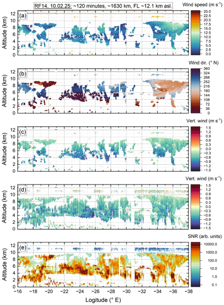
At the beginning of the flight on 10 February 2026, HALO climbed to an altitude of approximately 12.1 km and flew above a sub-visible ice cloud extending from about 10 km down to approximately 2 km. The cloud provided sufficient backscatter to achieve a high SNR and consequently an excellent measurement coverage for HEDWIG. During the approximately 1630 km long flight leg (purple segment in Fig. 4), HEDWIG was operated using six off-nadir LOS measurements separated by 60° in azimuth, interleaved with six nadir-pointing observations. With a dwell time of 1 s per LOS direction and including the time required to reposition the scanner wedges, one complete scan required 16.1 s. At the HALO cruise speed of approximately 230 m s−1, this corresponds to a horizontal sampling distance of about 3.7 km for the retrieved wind vectors. Since the scanner requires a total of 4.1 s to move between the six off-nadir and six interleaved nadir-pointing directions, the average transition time between successive LOS measurements is approximately 0.33 s.

Figure 6HEDWIG results from a ≈ 1630 km and 2 h long flight leg flown on 10 February 2026 (see also purple line in Fig. 4): (a) horizontal wind speed, (b) wind direction and (c) vertical wind speed retrieved from conical scan measurements, as well as (d) vertical wind with negative sign pointing downwards to the ground and (e) SNR retrieved from single nadir-pointing LOS measurements. The faint line at 12.1 km indicates the in-situ data from the HALO nose-boom.
For the nadir-pointing observations, vertical wind profiles are obtained every 2.7 s, corresponding to a horizontal sampling distance of approximately 620 m. Consequently, the vertical wind observations provide about six times higher temporal and spatial resolution than the retrieved horizontal wind vectors.
The retrieved wind products for this flight leg are presented in Fig. 6, showing (a) horizontal wind speed, (b) wind direction, and (c) vertical wind speed retrieved from the VAD scans (Sect. 3.2), together with (d) vertical wind velocity and (e) signal-to-noise ratio (SNR) obtained from the nadir-pointing measurements (Sect. 3.1). The thin line at 12.1 km a.s.l. indicates the simultaneous in-situ wind measurements from the HALO nose boom.
Panels (a) and (b) show generally weak horizontal winds below approximately 15 m s−1, while wind speeds at flight level reached about 25 m s−1, as indicated by the in situ measurements. Throughout most of the flight leg, the wind originated from northwesterly to westerly directions before gradually turning towards southeasterly directions near the end of the transect. At an altitude of around 6 km, between −20 and −28° E, a pronounced wind shear is evident, with the wind direction changing from westerly to northerly.
The vertical wind field derived from the conical scans (panel c) is dominated by negative velocities associated with the sedimentation of ice particles within the cloud. As expected, the largest downward velocities occur near the cloud base where ice particles are supposed to be largest. The data coverage of the retrieved wind vectors is noticeably lower than that of the individual nadir-pointing measurements shown in panels (d) and (e). This behavior is a consequence of the retrieval approach. A valid wind vector requires a sufficient number of successful LOS measurements during one scan. If several LOS observations are attenuated or completely blocked by optically thick cloud regions, as for instance at the top of the boundary layer, the corresponding wind-vector retrieval fails although valid measurements are still available along the remaining LOS directions. Future work will investigate combining observations from multiple consecutive scans to increase retrieval robustness under such conditions, at the expense of reduced horizontal resolution.
A comparison of panels (c) and (d), which are derived from essentially the same observations, clearly demonstrates the benefit of the dedicated nadir-pointing measurements which are possible with the HEDWIG scanner. Owing to their sixfold higher sampling resolution (2.7 s versus 16.1 s per complete measurement) and independent evaluation, small-scale updrafts and downdrafts that are only weakly resolved in the VAD retrieval become clearly visible. In addition, the data coverage is substantially improved because each nadir observation can be evaluated independently of neighboring LOS measurements, whereas the VAD method requires a minimum number of valid LOS points within a single scan cycle.
The corresponding range-corrected SNR is shown in panel (e) as an uncalibrated quantity being proportional to the atmospheric backscatter strength and hence, indicating regions of enhanced cloud backscatter. Areas with particularly high SNR generally coincide with reduced wind-vector coverage because strong cloud attenuation prevents some off-nadir laser beams from penetrating the complete measurement volume.
It should be noted that the sensitivity demonstrated during the first airborne measurements performed during NAWDIC was lower than initially expected from the transmitter performance. A subsequent analysis of the HEDWIG receiver revealed a small misalignment in the heterodyne detection path, which reduced the effective receiver sensitivity compared to the nominal instrument performance. Consequently, the measurements acquired during NAWDIC predominantly provide valid wind retrievals from optically thin cloud layers and enhanced aerosol backscatter in the planetary boundary layer, whereas reliable retrievals under background aerosol conditions were not yet achieved. This sensitivity limitation is therefore not considered representative of the final instrument performance. The receiver alignment has since been identified as an important aspect for further optimization, and its improvement is expected to increase the sensitivity to weak aerosol backscatter and thereby extend the range of atmospheric conditions accessible to HEDWIG.
Overall, these first airborne observations demonstrate the capability of HEDWIG to simultaneously retrieve horizontal wind vectors and high-resolution vertical wind velocities with high spatial and temporal resolution. A comprehensive performance assessment based on the complete NAWDIC data set and comparisons with independent reference observations will be presented in a follow-up study.
A new airborne heterodyne detection Doppler wind lidar, HEDWIG (Heterodyne Detection Wind lidar Gadget), has been developed at the German Aerospace Center (DLR) to provide high-resolution observations of atmospheric wind fields from the research aircraft HALO. The instrument combines a laser operating at 1617 nm with 2.7 mJ laser pulses and 750 Hz pulse repetition rate, and a newly developed double-wedge scanner that enables rapid and flexible beam steering while maintaining a compact and mechanically robust optical design suitable for airborne operation.
The paper describes the complete instrument, including the laser transceiver unit, scanner, data acquisition system and wind retrieval chain. Particular emphasis is placed on the synchronized acquisition of atmospheric signals together with aircraft navigation data and scanner encoder information, allowing accurate correction of aircraft motion and precise georeferencing of every individual laser pulse.
A key feature of HEDWIG is the high dynamic performance of the double-wedge scanner. In addition to conventional conical scanning for velocity–azimuth display (VAD) wind retrieval, the scanner allows rapid transitions to dedicated nadir-pointing observations. Consequently, horizontal wind vectors and high-resolution vertical wind profiles can be obtained almost simultaneously, substantially improving the temporal and spatial sampling of vertical air motions compared with conventional VAD measurements alone.
The instrument was successfully deployed for the first time during the North Atlantic Waveguide, Dry Intrusion and Downstream Impact Campaign (NAWDIC) in January and February 2026. Analyses of more than 4600 land-surface and sea-surface returns demonstrate a low systematic LOS Doppler velocity error below 0.1 m s−1 and a random error of about 0.2 m s−1 for single LOS measurements under high-SNR conditions. These values are fully consistent with the performance achieved by the predecessor airborne 2 µm Doppler wind lidar, demonstrating comparable high-SNR LOS Doppler velocity precision.
First airborne observations further demonstrate the capability of HEDWIG to retrieve horizontal wind vectors together with direct measurements of the vertical wind component over flight distances exceeding 1600 km. The combined measurement strategy reveals atmospheric structures over a wide range of spatial scales while significantly increasing the sampling of vertical motions compared with wind vectors retrieved solely from conical scanning.
This paper demonstrates the HEDWIG measurement principle and presents first results. Future work will exploit the complete NAWDIC data set for scientific investigations and detailed comparisons with independent wind observations. Owing to its unique combination of high pulse energy, flexible beam steering and simultaneous measurements of horizontal and vertical wind components, HEDWIG provides a powerful new observational capability for airborne atmospheric research and future validation of numerical weather prediction models as well as for wind measurements from space lidars and radars as for instance the Doppler velocity products of the cloud profiling radar on EarthCARE, but also for future missions as WIVERN and Aeolus-2. The combined measurements with the WALES lidar onboard HALO allow water vapor and ozone flux measurements, which will be addressed in future work.
The code that is used for data analysis (LabVIEW vi) and for figure plotting (OriginLab) can principally be provided upon request.
The HEDWIG data discussed here and for all 19 research flights performed during the NAWDIC campaign will be made publically available in March 2027 and will be provided on the HALO data base available at https://halo-db.pa.op.dlr.de/ (last access: 9 November 2026).
BW conceived the HEDWIG instrument and served as its principal investigator. He led the development and integration of the instrument, including the optical, mechanical and electronic subsystems, developed the instrument control and data acquisition software, conducted the airborne measurements, supported the data analysis, and prepared the manuscript. EK contributed to the laboratory integration and data analysis and developed the scanner control software, including the implementation of the aircraft attitude correction. OK was responsible for the design and development of the majority of the mechanical components of HEDWIG and led the activities related to the airworthiness certification of the instrument. CL supported the instrument development as well as its deployment during the NAWDIC campaign. OL supported the deployment during the NAWDIC campaign and operated the HEDWIG instrument during the flights on 8 and 10 February 2026. SR developed the wind retrieval software for both the LOS Doppler velocity retrieval and the VAD-based horizontal wind vector retrieval. All authors contributed to the discussion of the results and reviewed the manuscript.
The contact author has declared that none of the authors has any competing interests.
Publisher's note: Copernicus Publications remains neutral with regard to jurisdictional claims made in the text, published maps, institutional affiliations, or any other geographical representation in this paper. The authors bear the ultimate responsibility for providing appropriate place names. Views expressed in the text are those of the authors and do not necessarily reflect the views of the publisher.
The authors gratefully acknowledge the support of Falk Metzen and Tanja Bodenbach (both DLR) during the development of HEDWIG. The valuable contributions of Keith Barr (Lockheed Martin), Sammy Henderson, Charley Hale, Dale Bruns and Ross Hartman (all Beyond Photonics), Christoph Bollig (Abacus Laser), Andreas Fix and Oliver Reitebuch (both DLR) are also gratefully acknowledged. The authors further thank Julian Quinting (University of Cologne), Annika Oertel and Bastian Kirsch (both KIT), Andreas Schäfler (DLR), and Shira Raveh-Rubin (Weizmann Institute of Science) for the excellent organization and execution of the NAWDIC campaign. Finally, the authors gratefully acknowledge the support of the DLR Flight Experiments facility, the DLR Design Organization, and the HALO flight crews. The authors express their gratitude to Daniel Schiller (DLR) for supporting the activities related to the development of the HEDWIG instrument. Language editing assistance was provided using ChatGPT (OpenAI). The valuable comments by an anonymous reviewer and Kristopher Bedka (NASA), as well as by Stefan Kaufmann (DLR) are appreciated.
This research has been supported by the Deutsches Zentrum für Luft- und Raumfahrt (Internal Aeolus-2 Project) and the Deutsche Forschungsgemeinschaft (grant no. 552644175).
The article processing charges for this open-access publication were covered by the German Aerospace Center (DLR).
This paper was edited by Ulla Wandinger and reviewed by Kristopher M. Bedka and one anonymous referee.
Amirault, C. T. and DiMarzio, C. A.: Precision pointing using a dual-wedge scanner, Appl. Optics, 24, 1302–1308, https://doi.org/10.1364/AO.24.001302, 1985. a
Augere, B., Valla, M., Durécu, A., Dolfi-Bouteyre, A., Goular, D., Gustave, F., Planchat, C., Fleury, D., Huet, T., and Besson, C.: Three-Dimensional Wind Measurements with the Fibered Airborne Coherent Doppler Wind Lidar LIVE, Atmosphere, 10, https://doi.org/10.3390/atmos10090549, 2019. a
Bedka, K., Marketon, J., Henderson, S., and Kavaya, M.: AWP: NASA's Aerosol Wind Profiler Coherent Doppler Wind Lidar, in: International Workshop on Space-Based Lidar Remote Sensing Techniques and Emerging Technologies, Springer, 27–35, https://doi.org/10.1007/978-3-031-53618-2_3, 2023. a, b
Bedka, K., Marketon, J., Khlopenkov, K., Cooney, J., Applin, S., Traore, A., Begay, S., Wilson, G., Cross, M., Noe, A., Henderson, S., Diamond, J., and KAvaya, M.: Aerosol Wind Profiler (AWP) Doppler Wind Lidar Airborne Observations During the NOAA JointVenture 3-D Wind Measurement Demonstration and NASA Active-Passive Profiling Experiment (APEX), in: 105th American Meteorological Society (AMS) Annual Meeting, New Orleans, LA, Country: US 12–16 January 2025, https://ntrs.nasa.gov/citations/20250000324 (last access: 14 October 2026), 2025. a, b, c
Bedka, K., Marketon, J., Henderson, S., Khlopenkov, K., Cooney, J., Kavaya, M., Applin, S., Wilson, F. G., Begay, S., Cross, M., Diamond, J., Emmett, A., Emmitt, G. D., Greco, S., Kratovil, P., Noe, A., and Traore, A.: The NASA Aerosol Wind Profiler Doppler Wind Lidar, Part I: Instrument Description and Airborne Demonstration, EGUsphere [preprint], https://doi.org/10.5194/egusphere-2026-4872, 2026. a, b
Beyon, J. Y., Arthur, G. E., Koch, G. J., and Kavaya, M. J.: Noise whitening in airborne wind profiling with a pulsed 2-micron coherent doppler lidar at NASA Langley Research Center, in: SPIE Defense, Security, and Sensing, International Society for Optics and Photonics, 83790N, https://doi.org/10.1117/12.919246, 2012. a
Browning, K. and Wexler, R.: The determination of kinematic properties of a wind field using Doppler radar, J. Appl. Meteorol. Clim., 7, 105–113, https://doi.org/10.1175/1520-0450(1968)007<0105:tdokpo>2.0.co;2, 1968. a, b
Cézard, N., Valla, M., Lombard, L., Augere, B., Lahyani, J., Patiño-Rosas, W., Goular, D., Planchat, C., Dolfi-Bouteyre, A., Durecu, A., Gustave, F., Liméry, A., Quatrevalet, M., Wolkiewiez, E., and Crevoisier, C.: Airborne Lidar measurements of wind profiles during the MAGIC-2021 campaign, EGUsphere [preprint], https://doi.org/10.5194/egusphere-2026-4286, 2026. a
Chouza, F., Reitebuch, O., Groß, S., Rahm, S., Freudenthaler, V., Toledano, C., and Weinzierl, B.: Retrieval of aerosol backscatter and extinction from airborne coherent Doppler wind lidar measurements, Atmos. Meas. Tech., 8, 2909–2926, https://doi.org/10.5194/amt-8-2909-2015, 2015. a, b
Chouza, F., Witschas, B., and Reitebuch, O.: Heterodyne high-spectral-resolution lidar, Appl. Optics, 56, 8121–8134, https://doi.org/10.1364/ao.56.008121, 2017. a
Frehlich, R., Hannon, S. M., and Henderson, S. W.: Coherent Doppler lidar measurements of winds in the weak signal regime, Appl. Optics, 36, 3491–3499, https://doi.org/10.1364/ao.36.003491, 1997. a
Gasch, P., Kasic, J., Maas, O., and Wang, Z.: Advancing airborne Doppler lidar wind profiling in turbulent boundary layer flow – an LES-based optimization of traditional scanning-beam versus novel fixed-beam measurement systems, Atmos. Meas. Tech., 16, 5495–5523, https://doi.org/10.5194/amt-16-5495-2023, 2023. a
Gasch, P., Wieser, A., Feuerle, T., Winter, F., and Bollig, C.: AIRflows - a novel airborne Doppler lidar for high resolution wind measurements, EGU General Assembly 2025, Vienna, Austria, 27 Apr–2 May 2025, EGU25-15290, https://doi.org/10.5194/egusphere-egu25-15290, 2025. a, b
Gatt, P., Barr, K., and Margulis, M.: WindTracer® evolution and recent measurement results, in: Applications of Lasers for Sensing and Free Space Communications, Optica Publishing Group, LT3D.2, https://doi.org/10.1364/lsc.2015.lt3d.2, 2015. a
Giez, A., Zöger, M., Mallaun, C., Nenakhov, V., Schimpf, M., Grad, C., Numberger, A., and Raynor, K.: Determination of the measurement errors for the HALO basic data system BAHAMAS by means of error propagation, DLR, Oberpfaffenhofen, Tech. Rep. No. 2022-27, https://doi.org/10.57676/5rdc-q708, 2023. a
Hamada, Y., Kikuchi, R., and Inokuchi, H.: LIDAR-based Gust Alleviation Control System: Obtained Results and Flight Demonstration Plan, 21st IFAC World Congress, IFAC-PapersOnLine, 53, 14839–14844, https://doi.org/10.1016/j.ifacol.2020.12.1928, 2020. a, b, c
Henderson, S., Yuen, E., and Fry, E.: Fast resonance-detection technique for single-frequency operation of injection-seeded Nd: YAG lasers, Opt. Lett., 11, 715–717, https://doi.org/10.1364/ol.11.000715, 1986. a
Henderson, S., Kavaya, M., Yu, J., Marketon, J., and Bedka, K.: Coherent Lidar for Airborne Wind Measurements with High-Percentage Tropospheric Coverage, in: Optica Advanced Photonics Congress 2022, Optica Publishing Group, LsM6C.2, https://doi.org/10.1364/LSC.2022.LsM6C.2, 2022. a, b
Henderson, S., Kavaya, M., Yu, J., Kratovil, P., Diamond, J., Hale, C., Bruns, D., Petway, L., Marketon, J., and Bedka, K.: Advanced Eyesafe Lidar for Atmospheric Wind Measurements, 21st Coherent Laser Radar Conference, 27 June–1 July 2022, Big Sky, MT, USA, https://beyondphotonics.com/publications/ (last access: 14 October 2026), 2022. a, b
Kavaya, M. J., Beyon, J. Y., Koch, G. J., Petros, M., Petzar, P. J., Singh, U. N., Trieu, B. C., and Yu, J.: The Doppler aerosol wind (DAWN) airborne, wind-profiling coherent-detection Lidar system: overview and preliminary flight results, J. Atmos. Ocean. Tech., 31, 826–842, https://doi.org/10.1175/jtech-d-12-00274.1, 2014. a, b, c
Koks, D.: Using rotations to build aerospace coordinate systems, DSTO Systems Sciences Laboratory, https://open-dis.github.io/dis-tutorial/documents/UsingRotationsToBuildAer ospaceCoordinateSystems.pdf (last access: 14 October 2026), 2008. a
Köpp, F., Rahm, S., and Smalikho, I.: Characterization of Aircraft Wake Vortices by 2-μm Pulsed Doppler Lidar, J. Atmos. Ocean. Tech., 21, 194–206, https://doi.org/10.1175/1520-0426(2004)021<0194:COAWVB>2.0.CO;2, 2004. a
Quinting, J., Grams, C. M., Kirsch, B., Oertel, A., Ramos, A. M., Raveh-Rubin, S., and Schäfler, A.: Dry Intrusion Connects High-Impact Cyclones Eunice and Franklin: Emerging Observational Targets of NAWDIC, B. Am. Meteorol. Soc., 107, E1302–E1314, https://doi.org/10.1175/BAMS-D-25-0170.1, 2026. a, b
Reitebuch, O., Werner, C., Leike, I., Delville, P., Flamant, P. H., Cress, A., and Engelbart, D.: Experimental Validation of Wind Profiling Performed by the Airborne 10-μm Heterodyne Doppler Lidar WIND, J. Atmos. Ocean. Tech., 18, 1331–1344, https://doi.org/10.1175/1520-0426(2001)018<1331:EVOWPP>2.0.CO;2, 2001. a
Schäfler, A., Craig, G., Wernli, H., Arbogast, P., Doyle, J. D., McTaggart-Cowan, R., Methven, J., Rivière, G., Ament, F., Boettcher, M., Bramberger, M., Cazenave, Q., Cotton, R., Crewell, S., Delanoë, J., Dörnbrack, A., Ehrlich, A., Ewald, F., Fix, A., Grams, C. M., Gray, S. L., Grob, H., Groß, S., Hagen, M., Harvey, B., Hirsch, L., Jacob, M., Kölling, T., Konow, H., Lemmerz, C., Lux, O., Magnusson, L., Mayer, B., Mech, M., Moore, R., Pelon, J., Quinting, J., Rahm, S., Rapp, M., Rautenhaus, M., Reitebuch, O., Reynolds, C. A., Sodemann, H., Spengler, T., Vaughan, G., Wendisch, M., Wirth, M., Witschas, B., Wolf, K., and Zinner, T.: The North Atlantic Waveguide and Downstream Impact Experiment, B. Am. Meteorol. Soc., 99, 1607–1637, https://doi.org/10.1175/bams-d-17-0003.1, 2018. a, b
Schäfler, A., Harvey, B., Methven, J., Doyle, J. D., Rahm, S., Reitebuch, O., Weiler, F., and Witschas, B.: Observation of jet stream winds during NAWDEX and characterization of systematic meteorological analysis errors, Mon. Weather Rev., 148, 2889–2907, https://doi.org/10.1175/mwr-d-19-0229.1, 2020. a
Smalikho, I.: Techniques of wind vector estimation from data measured with a scanning coherent Doppler lidar, J. Atmos. Ocean. Tech., 20, 276–291, https://doi.org/10.1175/1520-0426(2003)020<0276:towvef>2.0.co;2, 2003. a, b, c, d
Vasiljevic, N., Lea, G., Courtney, M., Cariou, J.-P., Mann, J., and Mikkelsen, T.: Long-Range WindScanner System, Remote Sensing, 8, https://doi.org/10.3390/rs8110896, 2016. a, b
Weissmann, M. and Cardinali, C.: Impact of airborne Doppler lidar observations on ECMWF forecasts, Q. J. Roy. Meteor. Soc., 133, 107–116, https://doi.org/10.1002/qj.16, 2007. a, b
Wirth, M., Fix, A., Mahnke, P., Schwarzer, H., Schrandt, F., and Ehret, G.: The airborne multi-wavelength water vapor differential absorption lidar WALES: system design and performance, Appl. Phys. B, 96, 201–213, https://doi.org/10.1007/s00340-009-3365-7, 2009. a
Witschas, B., Rahm, S., Dörnbrack, A., Wagner, J., and Rapp, M.: Airborne wind lidar measurements of vertical and horizontal winds for the investigation of orographically induced gravity waves, J. Atmos. Ocean. Tech., 34, 1371–1386, https://doi.org/10.1175/jtech-d-17-0021.1, 2017. a, b, c, d, e, f
Witschas, B., Lemmerz, C., Geiß, A., Lux, O., Marksteiner, U., Rahm, S., Reitebuch, O., and Weiler, F.: First validation of Aeolus wind observations by airborne Doppler wind lidar measurements, Atmos. Meas. Tech., 13, 2381–2396, https://doi.org/10.5194/amt-13-2381-2020, 2020. a, b, c
Witschas, B., Lemmerz, C., Geiß, A., Lux, O., Marksteiner, U., Rahm, S., Reitebuch, O., Schäfler, A., and Weiler, F.: Validation of the Aeolus L2B wind product with airborne wind lidar measurements in the polar North Atlantic region and in the tropics, Atmos. Meas. Tech., 15, 7049–7070, https://doi.org/10.5194/amt-15-7049-2022, 2022. a
Witschas, B., Gisinger, S., Rahm, S., Dörnbrack, A., Fritts, D. C., and Rapp, M.: Airborne coherent wind lidar measurements of the momentum flux profile from orographically induced gravity waves, Atmos. Meas. Tech., 16, 1087–1101, https://doi.org/10.5194/amt-16-1087-2023, 2023. a, b
Yew, R. L., Johnson, B. C., Gibson, B. C., and Mohamed, A.: A review of airborne Doppler lidar for wind-sensing, Prog. Aerosp. Sci., 157, 101127, https://doi.org/10.1016/j.paerosci.2025.101127, 2025. a
Yu, J., Lee, J., Wong, T.-H., Petway, L., Traore, A., Chen, S., Marketon, J., Kavaya, M., Henderson, S., Kratovil, P., Hale, C., Diamond, J., Bruns, D., Vanasse, N., and D'Epagnier, D.: Efficient Ho: LuLiF MOPA Laser Transmitter for Space Pathfinder Coherent Wind Lidar, in: 21st Coherent Laser Radar Conference, 26 June–1 July 2022, Big Sky, MT, USA, https://ntrs.nasa.gov/citations/20220008811 (last access: 14 October 2026), 2022. a
- Abstract
- Introduction
- Instrument description
- Measurement procedure and wind retrieval
- First airborne measurements performed during the NAWDIC campaign
- Summary and conclusion
- Code availability
- Data availability
- Author contributions
- Competing interests
- Disclaimer
- Acknowledgements
- Financial support
- Review statement
- References
- Abstract
- Introduction
- Instrument description
- Measurement procedure and wind retrieval
- First airborne measurements performed during the NAWDIC campaign
- Summary and conclusion
- Code availability
- Data availability
- Author contributions
- Competing interests
- Disclaimer
- Acknowledgements
- Financial support
- Review statement
- References