the Creative Commons Attribution 4.0 License.
the Creative Commons Attribution 4.0 License.
 | 05 Apr 2019
Novel specular meteor radar systems using coherent MIMO techniques to study the mesosphere and lower thermosphere
Jorge Luis Chau
Juan Miguel Urco
Juha Pekka Vierinen
Ryan Andrew Volz
Matthias Clahsen
Nico Pfeffer
Jörg Trautner
Typical specular meteor radars (SMRs) use one transmitting antenna and at least a five-antenna interferometric configuration on reception to study the mesosphere and lower thermosphere (MLT) region. The interferometric configuration allows the measurement of the angle-of-arrival (AOA) of the detected meteor echoes, which in turn is needed to derive atmospheric parameters (e.g., mean winds, momentum fluxes, temperatures, and neutral densities). Recently, we have shown that coherent MIMO configurations in atmospheric radars, i.e., multiple input (transmitters) and multiple output (receivers), with proper diversity in transmission can be used to enhance interferometric atmospheric and ionospheric observations. In this study we present novel SMR systems using multiple transmitters in interferometric configuration, each of them employing orthogonal pseudorandom coded transmitted sequences. After proper decoding, the angle of departure (AOD) of the detected meteor echoes with respect to the transmitter site are obtained at each receiving antenna. We present successful bistatic implementations of (1) five transmitters and one receiver using coded continuous wave (CW) (MISO-CW), and (2) five transmitters and five receivers using coded CW (MIMO-CW). The latter system allows simultaneous independent observations of the specular meteor trails with respect to the transmitter (AOD) and with respect to the receiver (AOA). The quality of the obtained results is evaluated in terms of the resulting mean winds, the number of detections and the daily diffusion trail vs. altitude behavior. We show that the proposed configurations are good alternatives to explore the MLT region. When combined with multi-static approaches, they can increase the number of meteor detections, thereby improving the quality of atmospheric estimates and allowing the measurement of new atmospheric parameters (e.g., horizontal divergence, vorticity), The use of multiple collocated transmitters for interferometric AOD determination makes building a multi-static radar network easier logistically, as only one receiver per receiving site antenna is sufficient.
- Article
(2365 KB) - Full-text XML
- BibTeX
- EndNote


In the last few decades, specular meteor radars (SMRs) have contributed significantly to the understanding of the mesosphere and lower thermosphere (MLT) region by providing continuous measurements of MLT parameters. Typical SMRs work in a monostatic configuration, i.e., the transmitting and receiving antennas are collocated. They provide routine measurements of altitude-resolved mean winds, temperatures, momentum fluxes, and neutral densities averaged over a few hundred kilometers of horizontal distance (e.g., Hocking et al., 2001; Holdsworth et al., 2004a; Hocking, 2005; Stober et al., 2014; Younger et al., 2015). Moreover, they are composed of a small number of antenna elements, are relatively easy to install, and are commercially available.
These systems are composed of a single transmitting antenna (or array) and a collocated multiple-receiver interferometric configuration. Periodic pulses (coded and non-coded) are used at the point of transmission. On reception, most of these radars use the so-called Jones configuration for the antenna layout (Jones et al., 1998) to determine the angle of arrival (AOA) of the meteor echoes. The main characteristics of the majority of such systems can be found in Hocking et al. (2001) and Holdsworth et al. (2004a).
To improve the number of detections and also to resolve winds inside the illuminated volume, Stober and Chau (2015) proposed the multi-static and multifrequency approach MMARIA (Multi-static, Multifrequency Agile Investigations of the Atmosphere). The increased number of detections with respect to a monostatic system is mainly due to two factors: (1) new and independent detections of the same or different meteor trails are obtained in multi-static links, and (2) the effective Bragg wavelength is equal or larger than the monostatic Bragg wavelength, thus allowing the detection of larger radar cross sections and higher altitudinal coverage (e.g., Stober and Chau, 2015).
The original MMARIA concept consisted of adding bistatic interferometric receive-only stations at distances between 60 to 200 km from existing transmitter sites. Vierinen et al. (2016) extended the concept by adding multiple coded continuous wave (CW) transmitter stations to be received by the existing network, each of them transmitting at the same frequency but with different orthogonal codes. Furthermore, Chau et al. (2017) implemented MMARIA using closely located monostatic SMRs in northern Norway, transmitting at different frequencies. Preliminary wind field estimations in northern Germany using two pulsed transmitters with different frequencies, two coded CW transmitters, and five receiver stations have been recently presented by Stober et al. (2018).
As shown in Vierinen et al. (2016), the coded CW implementation presents many advantages with respect to traditional pulsed applications. Some of these advantages are that (1) for the same averaged power, the peak power is much lower (e.g., 500 W instead of 10 kW for a pulsed transmitter with a 5 % duty cycle), that (2) one could use the same frequency on different transmitting antennas with orthogonal codes, as is done in global positioning systems, and that (3) there are none of the range or Doppler ambiguities that are present in pulsed systems.
Each of the MMARIA implementations mentioned above has proven to be challenging to deploy and operate, particularly for routine observations. For example, the Leibniz Institute of Atmospheric Physics (IAP), in conjunction with the MIT Haystack Observatory, has implemented a coded-CW SMR network in northern Germany on a campaign basis. One of the biggest challenges during this project has been finding suitable locations for the transmitting stations in terms of security, societal perception of electromagnetic radiation hazards, legal issues, etc.
Urco et al. (2018) have shown that coherent multiple input (transmitters) and multiple-output (receivers) (MIMO) techniques can be useful for improving imaging and interferometric configurations in atmospheric and ionospheric radars. The techniques have been applied to studies of equatorial electrojet (EEJ) irregularities at the Jicamarca Radio Observatory (JRO), using three transmitting diversity schemes: time, polarization, and code. More recently, Urco et al. (2019) have used MIMO with time diversity to study polar mesospheric summer echoes (PMSE) in northern Norway. MIMO techniques have been intensively investigated and used in the fields of communications, information theory, radar remote sensing, and over-the-horizon radar (e.g Telatar, 1999; Huang et al., 2011; Foschini and Gans, 1998; Frazer et al., 2007).
In this work we propose novel SMR systems that have emerged from the combination of our previous efforts and experiences. This includes the MMARIA concept (multi-static approach), the coded CW approach, statistical inverse-problems theory (e.g., compressed sensing), and the need to reduce some of the logistical issues experienced in previous efforts. Our proposed systems make use of transmitting arrays in an interferometer-like configuration, with each antenna transmitting at the same frequency but with different codes and accompanying receiver stations at distances between 20 to 200 km, with each station using one or more receiving antennas (multi-static). Upon reception, the signals from each transmitter station can be individually decoded and interferometrically combined to find the angle of departure (AOD) of the meteor echoes with respect to the transmitter station. This architecture limits most of the deployment complexity to a few interferometric transmitter stations while still providing the benefits of existing multi-static and coded CW approaches.
We start by describing the typical interferometer configurations of existing SMRs, i.e., using a single transmitter and multiple receivers. Then we present the details of the two systems that we have tested, both of them having the same multiple-transmitter geometry. The observations and results for each system are presented in Sect. 4 and compared with close-by observations of a standard SMR system. The advantages and challenges of the proposed systems are discussed in Sect. 5, including options for upgrading existing standard systems and, more importantly, ideas for future networks of multi-static SMRs.
Although SMRs have existed since World War II, they started to become more useful for atmospheric studies when they were able to measure the AOAs of the detected echoes by using suitable interferometer configurations. Given the large variability of signal strength of meteor echoes (more than 6 orders of magnitude), configurations able to resolve the AOA within the whole sky are needed even when narrow transmitting antennas are used (e.g., Valentic et al., 1997).
Following the notation of Urco et al. (2018), the spatial coherence of a target located at (θR, ϕR) (elevation and azimuth) in the far-field with respect to the receiver interferometer, illuminated by transmitter p located at rp, and received by a pair of receivers m and n located at rm and rn, respectively, is given by the following equation:
where kR is the receiving wavenumber vector with , λ is the radar wavelength, is the separation between receivers m and n, and Δϕmn indicates the instrumental phase difference between receiver pair (m, n). This expression corresponds to a coherent single-input (transmitter) multiple-output (receiver) (SIMO) configuration, depicted in Fig. 1a. We are following this nomenclature to be consistent with a more general radar imaging problem when more than one target is present (e.g., Hysell and Chau, 2006).
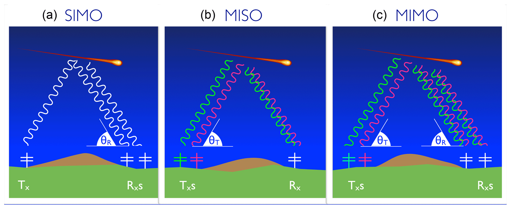
Figure 1A sketch representing three types of SMR systems: (a) the classic system of using a single transmitter and interferometer on reception (Rxs) (SIMO), (b) a proposed system using multiple transmitter (Txs) in interferometer mode at transmission and a single receiver (MISO), and (c) similar to (b) but with interferometry on reception (MIMO). In the case of MISO and MIMO, the transmitter waves forms are indicated with different colors, representing different diversity (different codes in our case). Note that elevation angles are measured with respect to the transmitter (θT, AOD) and/or receiver (θR, AOA).
For a deterministic target, an estimate of ρ(mnp) given by is obtained from the correlation of the complex voltages at receivers m and n due to transmitter p, vmp, and vnp, respectively. For stochastic targets, ensemble averages of this correlation are used (e.g., Urco et al., 2018, Eq. 2). At least two noncollinear pairs are needed to find the kr vectors (or AOAs).
Currently, the most common configuration in standard SMRs is the so-called five-antenna Jones interferometer (Jones et al., 1998). This configuration allows the possibility of resolving a short baseline for unambiguous determination and longer baselines for improving precision in two orthogonal directions. The typical antenna separations are 2.0λ and 2.5λ. These pairs of antennas allow a simple algebraic solution to the AOA estimation by working with the phase information of Eq. (1) (e.g., Hocking et al., 2001; Holdsworth et al., 2004a). However, for improved estimation and for logistical purposes, other configurations have been used and suggested (e.g., Younger and Reid, 2017). In such cases, e.g., a pentagon configuration or antennas not necessarily located on a plane, these simple algebraic solutions are no longer applicable. In such configurations, Younger and Reid (2017) have proposed the used of pre-calculated phases, while Vaudrin et al. (2018) has proposed a complex fitting approach with the inclusion of an uncertainty estimation of the resulting AOAs.
The phase difference between receivers m and n needs to be removed before the AOAs are estimated. Either they are measured using common feeding lines or echoes from targets with well-known locations, or they are empirically estimated using the expected distribution of underdense specular meteor echoes (e.g., Valentic et al., 1997; Hocking et al., 2001; Holdsworth et al., 2004b; Lau et al., 2006; Chau et al., 2008; Chau and Clahsen, 2019).
A simple way to understand the benefits of coherent MIMO configurations is by presenting the interferometric expression of a MISO configuration, i.e., multiple input (transmitters) single output (receivers). The MISO configuration is depicted in Fig. 1b. In this case the spatial coherence of a target located at (θT, ϕT) (elevation and azimuth) in the far-field with respect to the transmitter interferometer, illuminated by transmitters p and q located at rp and rq, respectively, and received by a single receiver m at rm is given by the following equation:
where kT is the transmitting wavenumber vector with , is the separation between the transmitters p and q, and Δϕpq indicates the instrumental phase difference between the transmitting pair (p, q). Therefore, the signal direction with respect to the transmitter kT (AOD) can be obtained from the cross correlation of received signals at antenna m, corresponding to transmitters p and q.
By combining the SIMO and MISO configurations, i.e., Eqs. (1) and (2), respectively, the spatial coherence expression for a coherent MIMO configuration is given by the following equation:
Following the notation of Stober and Chau (2015), the distance of the meteor echo to the transmitter and receiver are denoted by Ri and Rs, respectively.
A sketch of the MIMO configuration is given in Fig. 1c. In the case of MISO and MIMO, the diversity of transmissions is represented in Fig. 1 using two different colors. Recall that such diversity, depending on the target and the system, could be in time, polarization, or code. In the case of specular meteor echoes, polarization diversity is not an option since the different modes (ordinary or extraordinary) will suffer different amounts of group retardation (e.g, Elford, 2004). Based on the advantages described above, we find CW coding the most suitable diversity for our multi-static application. Below we discuss other possibilities using time diversity.
The above expressions are general for both monostatic and bistatic configurations. In the case of monostatic, the receiving (AOA) and transmitting (AOD) interferometric angles are the same for kR=kT, and the distances are also the same (Ri=Rs). Note that the expressions are given for far-field conditions with respect to each interferometer, i.e., the separation between interferometer antennas is much smaller than the distance to the meteor echo, and for the receiver and transmitter interferometers, respectively. In other words, MIMO provides the ability to “steer” the transmit beam on reception (in software), therefore providing the ability to maximize the transmit power incident on each meteor trail present in the field of view.
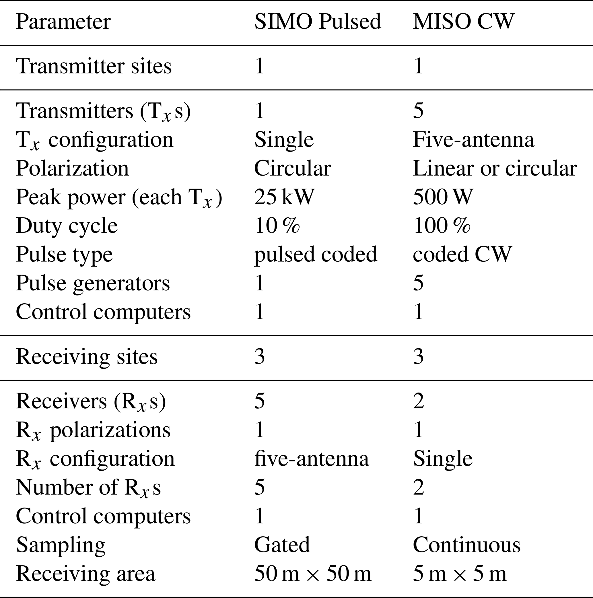
To implement our two multi-static multiple transmitter systems, we have used a transmitter array in Kühlungsborn and a receiver array in Neustrelitz (located ∼123 km from Kühlungsborn). At transmission a five-antenna 2.45λ equilateral pentagon configuration using a linear polarization was used. Different simultaneous orthogonal pseudorandom coded CW sequences were used on each transmitting antenna. The sequence was repeated every 10 ms. On reception, we used a five-antenna Jones configuration using circularly polarized antennas. Instead of the traditional 2.0λ and 2.5λ spacings, 1.0λ and 1.5λ spacings were used. Such a configuration has been successfully implemented at the Alta SMR in northern Norway. In the first implementation we used all five transmitting antennas and only one receiving antenna (MISO-CW). In the second implementation we use all five receiving antennas (MIMO-CW).
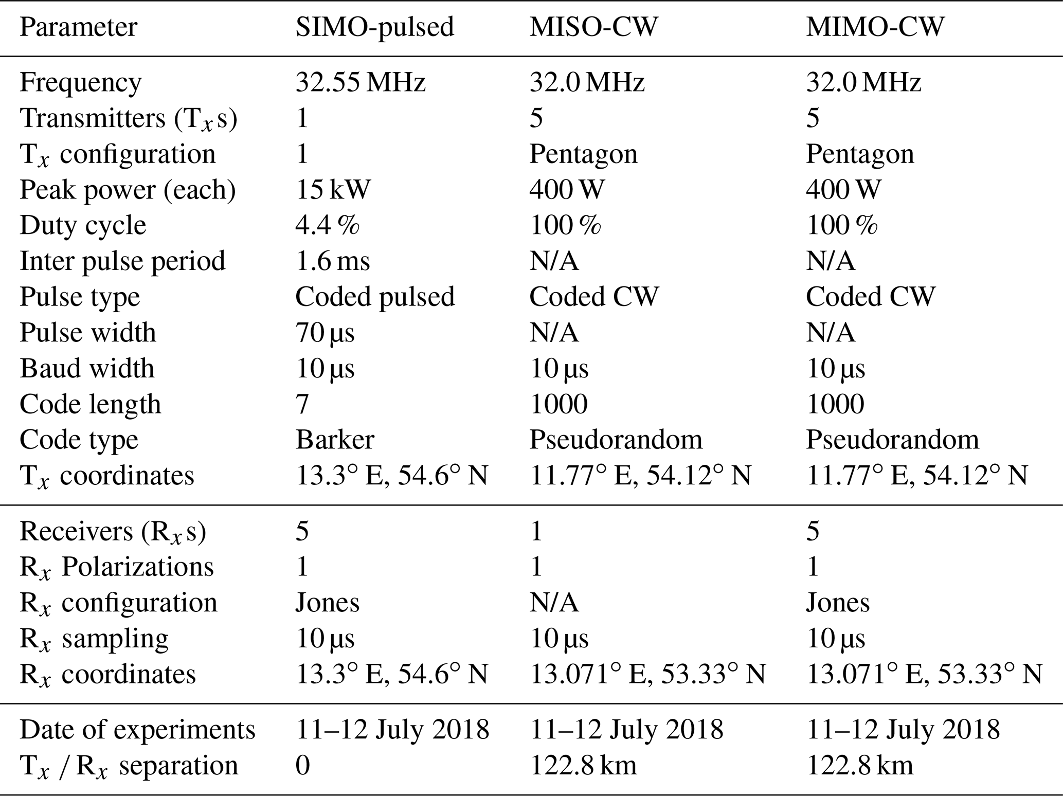
The main experimental parameters of each system can be found in Table 1. For completeness, we are also including the parameters of the monostatic system located in Juliusruh that is used below as a reference. Note that all multiple transmitter experiments have been performed with customized transmitter and receiver hardware and software developed and integrated at IAP in collaboration with colleagues from MIT Haystack Observatory and the UiT Arctic University of Norway. At transmission, five CW Hilberling linear transmitters were used, and the wave forms generated on a PC and communicated to the transmitters by USRP-N200 units. On reception, multiple USRP-N200 units were also used. All the units were independently synchronized to the global reference clock using a Trimble Thunderbolt GPS disciplined oscillator (GPSDO). Currently, none of these coded CW experiments could be implemented by existing commercially available SMR systems.
In the next section, we present the preliminary results of each system and some details of the decoding process. The specific details of the applied decoding processes in this work and those that are currently being improved will be given in a separate paper.
The data quality of our proposed systems is compared qualitatively and quantitatively (when relevant) to observations made with a standard monostatic SMR located in Juliusruh in northern Germany (54.63∘ N, 13.37∘ E). The main operational parameters of the Juliusruh radar are shown in Table 1. Following the nomenclature above, these observations are labeled SIMO-pulsed.
Table 2Summary of SMR implementations. Only detections with zenith angle with respect to the reference that are smaller than 60∘ are included under “selected counts”.
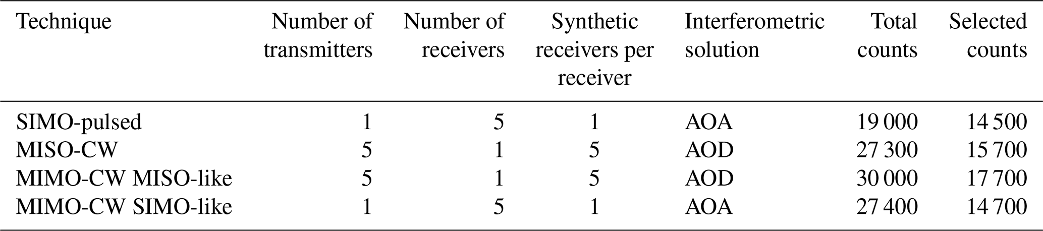

Figure 2MLT observations with a monostatic SMR system at Juliusruh on 11 July 2018. The first row shows a (a) time histogram, (b) 2-D histogram of altitude vs. inverse decay time (log scale) color-coded in linear scale, (c) altitude histogram, (d) 2-D histogram of latitude vs. longitude (linear scale). The zonal and meridional winds in bins of 1 h and 2 km are presented in the second and third rows, respectively. Note that the region of fewer counts in (d) is over the radar site.
Figure 2 shows selected measurements of basic parameters obtained on 11–12 July 2018 for the Juliusruh SMR: (a) time histogram, (b) 2-D histogram of altitude vs. inverse of meteor decay time (in linear scale), (c) altitude histogram, and (d) 2-D histogram of latitude vs. longitude (in linear scale). The total number of good counts are indicated in the time histogram plot in blue, while the number of detections with zenith angles less than 60∘ is indicated in black. In this particular campaign, close to 19 000 useful detections were obtained. In previous years for similar days, close to 24 000 meteors were observed using 30 kW peak power. In addition, zonal and meridional winds in 1 h and 2 km bins are shown in the second and third rows, respectively. These winds have been obtained with those detections within the white circle in Fig. 2d (i.e., with zenith angles less than 60∘). These observations are typical of the midlatitude mesosphere during summer months (e.g., Hoffmann et al., 2010).
The latitude vs. longitude 2-D histogram are plotted over a geographic map. The locations of the transmitter and receiver sites are indicated with white solid circles, in this case the same location. Note that Juliusruh is located 118 and 146 km from Kühlungsborn and Neustrelitz sites, respectively.
4.1 MISO-CW results
In this section we present the results of the MISO-CW system that were obtained using the transmitter pentagon configuration described above and one circularly polarized receiving antenna. The decoding process was done on signals from one receiving antenna using a compressed sensing approach on the complex raw voltages. Following a more common radar terminology, our procedure combines a matched filter estimator (MFE) and a maximum likelihood estimator (MLE). The MLE is used to detect the strong echoes, whose signals are then removed from the complex voltages. After this initial identification and removal, an MFE is applied to go after the remaining medium to weak echoes. In both cases, the time and range location of the echoes is obtained. Finally a minimum least-squares-error estimator is used to estimate the complex voltages of echoes at the pre-detected positions (time and range). In the case of a single transmitter, the MLE results could be equivalent to the results of an inverse filter, depending on the code selected. Our implementation is a modified version of the Generalized Orthogonal Matching Pursuit algorithm (Wang et al., 2012). Note that as a result of this processing, five different complex signals corresponding to each transmitting antenna are obtained for each detected meteor. More details and discussion of the techniques implemented here and those being developed will be given in a separate paper.
Figure 3 shows an example of range time intensity (RTI) from a MISO-CW system obtained on 12 July at 05:09 UT. The decoded signals of five synthetic receivers corresponding to all five transmitters and one physical receiving antenna have been incoherently integrated. Note that more than 30 specular meteor echoes are observable with the naked eye, along with echoes from an airplane.
An identification process based on the works of Hocking et al. (2001) and Holdsworth et al. (2004a) was applied to the complex voltages of the detected events. In this process we determine, among other parameters, total range detection, Doppler frequency, AODs, correlation time, detection time, etc., of each meteor echo. Namely, the AOD is obtained from the cross correlation of the complex voltages corresponding to different transmitting antennas, while the Doppler and correlation times are obtained from the averaged autocorrelation. The AOD estimation was done using a combination of beam forming and a complex fitting approach (e.g., Vaudrin et al., 2018; Chau and Clahsen, 2019). Given the relatively long baselines of the pentagon configuration, the altitude information was also used to remove angular ambiguities on low-elevation echoes.
Based on the AODs, the detection range, the location of the transmitter and receiver sites, the Bragg vectors, and incident and scattering ranges were calculated (e.g., Stober and Chau, 2015, Eq. 1). AODs were obtained using Eq. (2). Furthermore, the zonal and meridional winds were estimated for the same bins used for the standard Juliusruh system shown in Fig. 2 after calculating Bragg vectors and the Doppler shifts (e.g., Chau et al., 2017, Eq. 1).
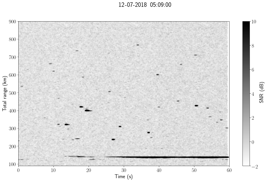
Figure 3An example of a range–time intensity plot obtained on 12 July 2018 at 05:09 UT with MISO-CW. More than 30 specular meteor echoes can be observed, in addition to airplane detection. Note that total range is used, i.e., the range from the transmitter to the echo plus the range from the echo to the receiver.
The resulting parameters of the MISO-CW system are shown in Fig. 4 in a similar manner to Fig. 2. The salient features of these results are (a) the wind, time, and altitude histograms are in excellent qualitative agreement with the corresponding Juliusruh results (i.e., Fig. 2); (b) the number of detected meteors is about 27 000 total with about 15 500 selected with zenith angles less than 60∘; and (c) the 2-D latitude vs. longitude histograms show the expected elliptical distribution has its foci at the receiver and transmitter sites, indicated with small white circles. The 2-D altitude vs. inverse decay histograms are also in good qualitative agreement with the SIMO-pulsed results, and the expected, small differences can be attributed to the small phase offsets and the different Bragg wavelengths that were excited. Note that the circle in Fig. 4d denotes the area of detection with zenith angles that are smaller than 60∘ with respect to the transmitter, which were used to estimate the zonal and meridional winds.
4.2 MIMO-CW results
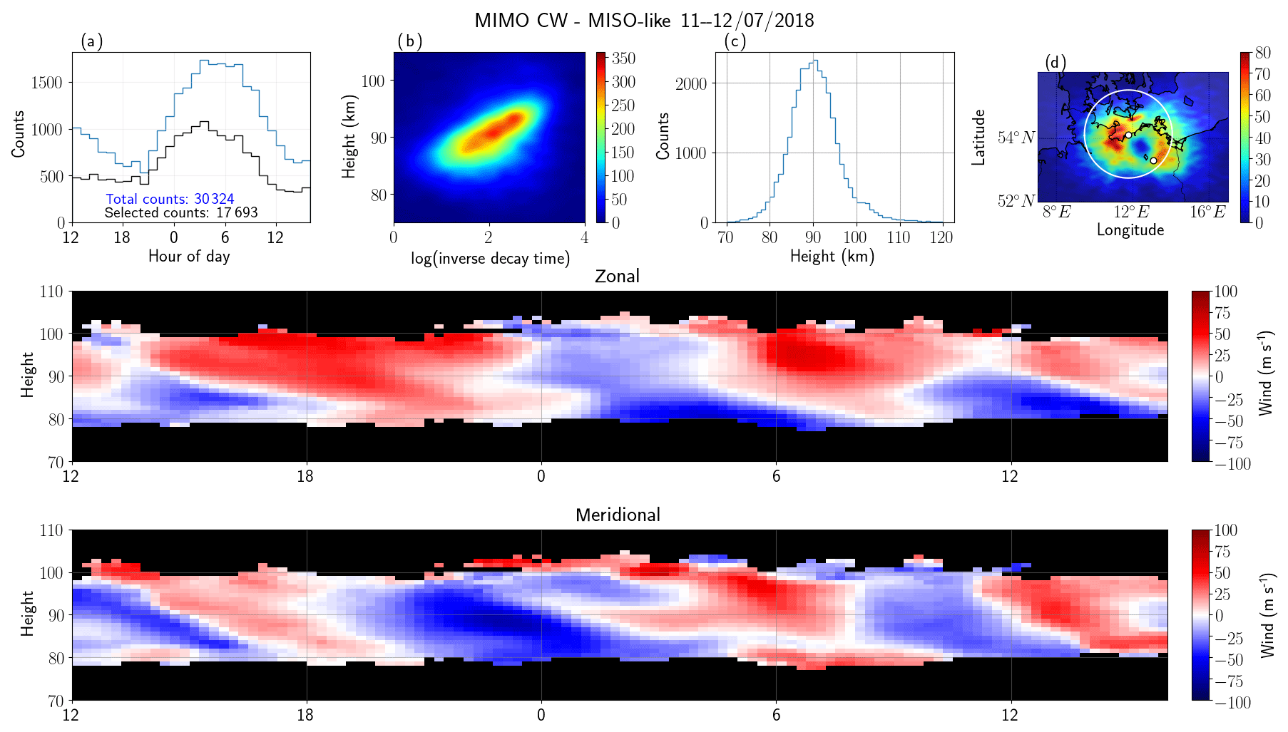
Now we present the results for the MIMO-CW system using five linearly polarized transmitters at Kühlungsborn and five circularly polarized receivers at Neustrelitz. After applying the same decoding process used in the MISO-CW system above for each transmit–receive pair, 25 synthetic receiving channels are obtained. Recall that for each receiving antenna the complex voltages corresponding to each transmitting antenna is obtained. Figure 5 shows the RTI obtained after incoherently integrating the signals of all 25 synthetic receiver channels for the same time used in Fig. 3. Given that more independent receiver signals are used, the noise variance is reduced, allowing us to observe more specular meteor echoes (more than 45).
At this point we could have proceeded by solving the location of the meteor echoes using all 25 antennas at the same time, i.e., using Eq. (). In principle, this is doable and it would require converting all the measurements to a common reference (e.g., the center of the Earth) and performing beam forming from two different observing centers. To simplify the presentation of the MIMO results, we process subsets of the 25 synthetic receivers in MISO-like and SIMO-like configurations; i.e., interferometric solutions with respect to the transmitter and receiver using Eqs. (2) and (1), respectively. We are leaving the use of all 25 receiving signals simultaneously, i.e., Eq. (), for a future effort.
Figure 6 shows the results of the MIMO-CW system but processed in a MISO configuration (MIMO-CW MISO-like), using the information of the five transmitters in only one physical receiving antenna to obtain the AODs, Doppler shift, total range, and diffusion time. The results are in excellent qualitative agreement with the results of MISO-CW, as expected since they used practically the same information. The main difference is the increased number of detections (∼30 000 and 17 700 instead of ∼27 300 and 15 700 for the total and selected counts, respectively). This increased number is expected due to the increased number of synthetic receivers used for detection (25), which in turn reduces the noise variance.
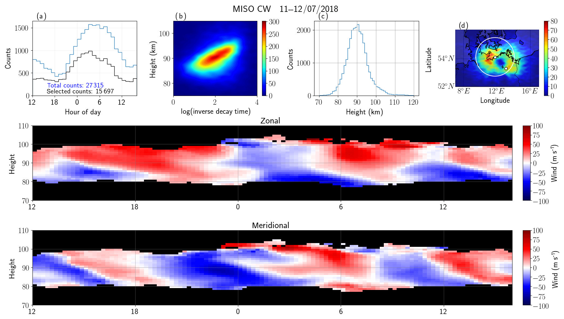
Figure 4Similar to Fig. 2 but for the MISO-CW system, i.e., the signals of five synthetic receivers have been incoherently integrated. The transmitter and receiver sites are indicated with small white circles in (d). Note that the region of fewer counts in (d) is over the midpoint of the receiver and transmitter sites.
The results of MIMO-CW processed in a SIMO configuration (MIMO-CW SIMO-like), using the information of only one transmitter in all five physical receiving antennas, are shown in Fig. 7. Qualitatively, these results also compare very well to the Juliusruh results (Fig. 2). However, given that only one transmitter is used, the number of counts is slightly fewer than MIMO-CW MISO-like: ∼27 000 to 14 700 instead of ∼30 000 to 17 700 for the total and selected counts, respectively. Other salient differences with respect to MIMO-CW MISO-like are (a) the observed specular meteor echoes close to 70 km and above 110 km and (b) the different shape of the 2-D latitude–longitude histogram. The former might be due to small remaining phase calibration issues or small imperfections in the geometry of the receiving antennas, while the latter is related to the different interferometric configuration and location. For example, at Kühlungsborn there are some small hills to the south, causing different transmit and receive propagation paths, particularly at very low elevation angles.
In order to have a quantitative comparison, in Fig. 8 we present scatterplots of the zonal and meridional wind components using SIMO-pulsed (i.e., SIMO JRUH32) as a reference for MISO-CW (first column), MIMO-CW MISO-like (second column), and MIMO-CW SIMO-like (third-column). Despite the different sampling volumes, the winds from all three configurations are highly correlated with the Juliusruh winds, presenting Pearson correlation coefficients between 0.72 and 0.82. In the case of the other parameters, e.g., altitude distribution or altitude vs. inverse decay time distributions, we have not done a quantitative comparison since the effective Bragg wavelengths are different between the monostatic and multi-static links. Again, by looking at panels (b) and (d) in Figs. 2, 4, 6, and 7 the resulting distributions are in excellent qualitative agreement.
In Fig. 9, we compare the echo location obtained with MIMO-CW MISO-like and MIMO-CW SIMO-like analyses. The left panel shows the simultaneous meteor locations taken from both systems and color-coded with altitude differences. The larger (smaller) circles represent the loci of 60∘ (30∘) zenith angles with respect to each station. Figure 9c shows a 2-D histogram (in linear scale) for latitude difference vs. longitude difference. In general, both approaches provide practically the same horizontal position. The observed variances in longitude and latitude are mainly due to statistical uncertainties of the AODs and AOAs that are dependent on their corresponding interferometer configuration, signal-to-noise ratio, and elevation angle (e.g., Holdsworth, 2005; Vaudrin et al., 2018).
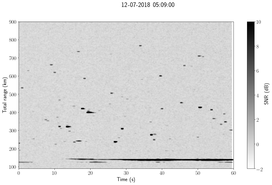
Figure 5Similar to Fig. 3 but for MIMO-CW system, i.e., the signals of 25 synthetic receivers have been incoherently integrated. More than 45 specular meteor echoes can be observed, in addition to an airplane detection.
The altitude difference for common detections is shown in Fig. 9c for (1) all common detections (blue), (2) for MISO detections lower than 60∘ at zenith and SIMO detections greater than 60∘ at zenith (yellow), and (3) for SIMO detections less than 60∘ zenith and MISO detections greater than 60∘ zenith (green). The y axis on the left corresponds to the blue curve, while the right axis corresponds to the yellow and green results.
In the case of altitude, the majority of echoes present a relatively narrow distribution. The larger altitude variances are due to a mix of statistical uncertainties, small imperfections in the antenna geometries, and effective phase calibration variations at low elevations. Note that larger altitude differences in Fig. 9c are shown for echoes occurring further from Neustrelitz and closer to Kühlungsborn (yellow curve in Fig. 9c) than from echoes closer to Neustrelitz and further from Kühlungsborn (green curve). This difference results from the Jones configuration used in Neustrelitz that has smaller baselines than the pentagon configuration used in Kühlungsborn. As mentioned above, combining all 25 synthetic receivers would provide one single solution as long as the MIMO system is well phase calibrated in both transmission and reception and the antenna locations are well known with respect to a single reference, e.g., the Earth's center.

A summary of the basic parameters for the different implementations presented in this work, including number of transmitters, number of receivers, number of synthetic receivers per physical receiver, and counts, is shown in Table 2. Our preliminary results confirm that our novel SMR MIMO systems are suitable solutions to study the MLT atmospheric dynamics with multi-static geometries, e.g., meteor counts using one transmitter station can be increased by adding multiple single-antenna receiver stations. However, the SMR MIMO systems are not without their challenges.
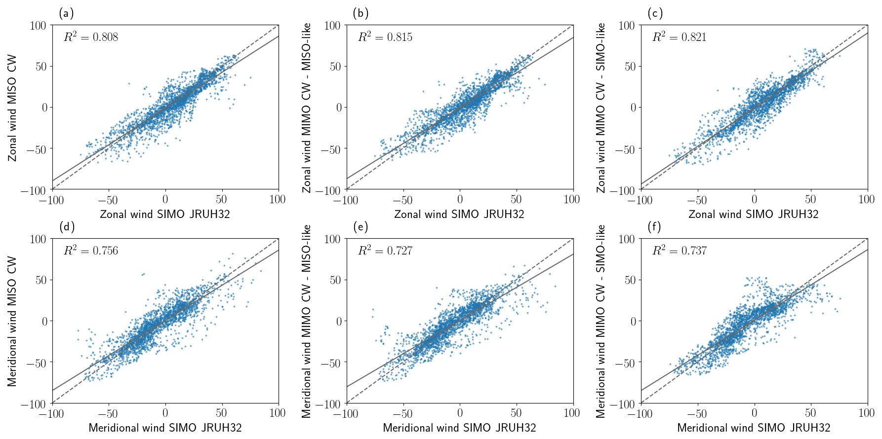
Figure 8Scatterplots of zonal and meridional wind components using the monostatic values as a reference (SIMO-JRUH32) for MISO-CW (a, d), MIMO-CW MISO-like (b, e), and MIMO-CW SIMO-like (c, f). The Pearson correlation coefficients are indicated on each scatterplot.
5.1 Challenges
5.1.1 Implementation
As mentioned above, the implementation of our proposed systems, i.e., MIMO with coded CW diversity, are currently not possible with commercially available SMR systems, either due to hardware or software limitations. Therefore, the realization and implementation of what we propose would require major upgrades to existing systems or in-house implementation of software-defined radar procedures like those implemented in this work, accompanied with some developments in hardware (e.g., very-high-frequency (VHF) CW transmitters or a pulsed transmitter with large duty cycles). Use of multiple sequences of pseudorandom large codes at transmission and the corresponding continuous sampling on reception are a couple of challenges with currently commercially available SMRs.
We have decided to test the MIMO concept using coded CW, which in practice is a form of spread spectrum, given the advantages described in the introduction and in Vierinen et al. (2016). However, MIMO implementations using time diversity in pulsed systems might be possible, particularly if the separation between pulses is relative small. For example, a sequence of pulses of a few microseconds wide and with a few microseconds of separation between them, i.e., staggered pulses, might also work. Such a scheme can be considered a subset of our proposed coded CW, where the code consists of −1, 0, and 1 values instead of just −1 and 1. Other groups might try to implement this or other options if they find MIMO attractive to their studies.
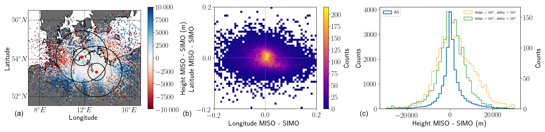
Figure 9Comparisons of MIMO-CW MISO-like and MIMO-CW SIMO-like: (a) latitude and longitude distributions color-coded with altitude differences, (b) 2-D histograms of differences in latitude and differences in longitude color-coded on a linear scale, and (c) histograms of altitude difference using all common detections (using left y axis). In (c) we also show the altitude difference histograms for MISO zenith angles lower than 60∘ and SIMO zenith angles greater than 60∘ (yellow), as well as for MISO zenith angles greater than 60∘ and SIMO zenith angles less than 60∘ (green) using the right y axis. The loci of 30∘ and 60∘ zenith angles, with respect to each site, are indicated with black circles in the left panel.
In the case of multi-static systems, time synchronization, frequency coherence, and time stability are key to the performance of the proposed systems. In our case we have selected code sequences that are repeated every 10 ms, and by using the one pulse per second from GPS receiver units, time synchronization between systems is possible within a few tens of nanoseconds precision.
5.1.2 Computation
The filtering and decoding required to process many channels of CW-coded links is not a trivial operation and can be computationally demanding. However, the implementation can be done nowadays on personal computers and be run much faster than the acquisition time. In the end, the problem is reduced to a statistical inverse problem, and as such, depending on the application and the environment, different optimal procedures are possible. For example, one can employ a maximum likelihood estimator, zero forcing, minimum mean-square error, or compressed sensing, to name a few possibilities (e.g., Vierinen et al., 2016; Klein et al., 1996; Jiang et al., 2011; Strohmer and Friedlander, 2009; Gao et al., 2017). In this work we have used a compressed sensing approach, given the natural sparsity of specular meteor echoes.
5.1.3 Self noise
In terms of signal-to-noise ratio (SNR), from the fact that we are transmitting different codes on the same frequency bandwidth, one would expect a degradation of SNR, particularly if conventional codes and decoding are used. However, the selection of nearly orthogonal pseudorandom codes, combined with advanced signal processing and statistical inverse problems theory, make such expected SNR degradation manageable. Increasing the code length to a maximum within signal coherence and time resolution constraints allows maximization of the SNR when analyzing links individually. In that case, it is most crucial to ensure that the codes sent by each transmitter are uncorrelated at zero lag because meteors will always appear with zero relative lag between links from the same transmission site. Given the sparse nature of SMR echoes, it is also possible to analyze all of the links collectively using compressed sensing approaches and minimize the effect of cross talk even further. More details on these arguments will be presented in a separate paper.
5.1.4 Cost
To facilitate the discussion about costs, we compare two multi-static systems: one using SIMO and one using MISO. The SIMO system would consist of a single transmitter system with 25 kW peak power and 10 % duty cycle and three receiving stations, each with five-antenna interferometry capability. The MISO system would consist of a single transmitter station with five 500 W CW transmitters with the same interferometer geometry as the receivers in SIMO and three single cross-polarized antenna located at the same places as the receivers in SIMO. In terms of transmitter costs, given that the average power is similar, the costs are expected to be similar. In the case of SIMO, one pulse generator will be needed, while for MISO five pulse generators are needed. On reception, the amount of hardware and space is significantly reduced for MISO compared to SIMO, one antenna, two receiving channels, and 5 m × 5 m of area instead of five antennas, five receiving channels, and 50 m × 50 m, respectively. Taken together, we expect the costs to be roughly similar, although if more links are desired, the incremental cost of MISO is much lower than SIMO. A summary of these values is shown in Table 3. Note that in this simple analysis, research and development costs are not included.
5.2 Advantages
In general, we think that these challenges are worth the benefits that they enable. The field of telecommunications also faced similar challenges, but in the end the advantages of MIMO techniques (e.g., amount of information on improved channels) were much greater than the implementation costs and small losses in SNR (e.g., Telatar, 1999; Zheng and Tse, 2003). As mentioned in the introduction, the proposed MIMO systems arose from the difficulty of building out a multi-static SMR network with multiple transmitter sites and multiple interferometric receiving stations. The original idea of adding receiving antennas with interferometry capability to existing transmitter sites (Stober and Chau, 2015), although much cheaper than a single monostatic SMR station, in practice has not been easy to implement, mainly due to logistical problems (area, fence, security, etc.). Our second parallel approach was to add single antenna coded CW transmitters to existing receiving arrays. The main challenge here has been dealing with societal perception of the dangers associated with a VHF transmitter near an occupied area. After a couple of years of experience exploring different options to realize the benefits of spatial information and additional counts from applying multi-static SMR approaches, we have come to strongly believe that the MISO-CW and MIMO-CW configurations provide the best path forward to implement multi-static SMR networks.
5.2.1 MISO-CW
In the case of the MISO-CW, once the transmitter with interferometer capability is installed, adding more multi-static links is relatively trivial. Each receiving station only requires a small area, and does not need permission to receive. The phase calibration is only necessary at one station: the transmitter site. Another scientific potential of MISO-CW is the possibility of receiving orthogonal linear (or circular) polarizations, thereby adding the ability to study polarization issues in meteor trails due to background electron density, Earth's magnetic field, and geometry. Although we are still at the testing stages, such systems could be installed in many places (e.g., in schools), and if efforts are placed to reduce the costs of hardware, deployment of receiving sites could even be extended to the general public to promote citizen science. Each receiver station, aside from providing data to a given network, could integrate an engaging display of real-time MLT winds and meteor detection maps, which would be particularly attractive to the general public during meteor showers.
5.2.2 MIMO-CW
Our second proposed system, MIMO-CW, would be the equivalent of a luxury model in a commercial line of products. In terms of costs, it would be the most expensive since we would not have the same benefit of having simple receiver stations, as is the case with MISO-CW. However, in terms of performance (number of detections, uncertainties in estimates, quality of measured parameters, separation between sites, etc.) it would be the best of the two options for the same geometry. Just from the detection point of view, one increases the number of incoherent integrations from 5 to 25, allowing the detection of weaker echoes. In terms of meteor location, AODs can be independently measured with respect to the transmitters, and AOAs with respect to the receiver sites, by using the information of one receiver and all the transmitters (MISO-like) and by using the information of one transmitter and all the receivers (SIMO-like), respectively, as we have done in this work. For relatively long links, detections have a larger elevation angle with respect to one of the sites than the other; therefore, AOA and AOD estimates will have less uncertainty (e.g., Hocking, 2018) with a MIMO system than with either a MISO or SIMO system. As far as we know, this is the first time such simultaneous independent measurements have been done with SMRs.
Larger uncertainties in altitude are expected for low elevation angle detections (e.g., Hocking, 2018; Holdsworth, 2005; Vaudrin et al., 2018). Moreover, larger uncertainties are expected for configurations with shorter antenna baselines (e.g., Holdsworth, 2005; Younger and Reid, 2017; Vaudrin et al., 2018). Therefore, the altitude differences of common detections in Fig. 9 are expected. Besides the statistical uncertainties, we have found that the differences are also sensitive to the precision of the interferometer geometry. These types of uncertainty are also expected in conventional SMR pulsed systems. AOA and AOD uncertainties for relatively low elevation angles could be reduced by employing larger baselines and more receiving antennas (e.g., Holdsworth, 2005) and/or by adding antennas with a significant distance in the vertical direction, e.g., an elevated antenna in the center of a pentagon (e.g., Younger and Reid, 2017). In general, having a good estimate of the AOA uncertainties can be useful in the derivation of atmospheric parameters even when using low-elevation meteor detections, as long as such uncertainties are properly propagated and included in the inversion processes.
As mentioned above, a more robust processing approach than division into MISO-like and SIMO-like configurations should provide a single meteor location, taking into account the geometry and interferometric configurations involved and the expected statistical uncertainties of AOAs and AODs. As shown by Vaudrin et al. (2018), AOA statistical uncertainties are not constant and depend on SNR, diffusion time, and zenith angle. For example, low-elevation high SNR detections can have a small AOA uncertainty, and therefore also have a small altitude uncertainty, which could be smaller in that case than for detections with a high elevation angle and lower SNR. The same arguments apply to AODs. Additionally, a complete Earth geometry should be integrated into the full solution when combining all 25 effective channels. In terms of receiver pairs, the full solution (instead of five effective channels at a time) would increase the number of pairs from 10 to 300, 30 times more. Although a MIMO-CW implementation might not be attractive for planning from scratch in terms of logistics, it might be attractive when built on top of existing receiving systems as in our case. In future efforts, we plan to implement variants of the approach proposed by Vaudrin et al. (2018) to real data, i.e., by using a complex fitting approach, to obtain uncertainties not only in Doppler and correlation time but also in direction cosines and, therefore, in location.
5.3 Comparison to monostatic
Recently Hocking (2018) has used near-worst-case values of uncertainties and simple geometrical arguments to stress the potential limitations of bistatic SMR systems. Our comparison of MIMO-CW MISO-like and MIMO-CW SIMO-like corroborates some of the warnings stressed, namely the large uncertainties in AOAs experienced at low elevation angles. However, instead of seeing limitations, we would like to stress the opportunities of such systems. For example, with conservative use of detections only at high elevation angles, as is done in existing monostatic systems, multi-static systems deployed at relative short distances (between 60 and 200 km, as suggested in previous works) provide a significant region of additional meteor counts with diverse observing geometries. Based on the arguments above, different interferometer configurations could be used to decrease the AOA uncertainties at low elevation angles and further increase the region of low-altitude uncertainty detections. Specifically, Holdsworth (2005) have suggested adding a fourth antenna to each Jones arm with a baseline of 20λ, and Younger and Reid (2017) have suggested adding a center antenna to a pentagon configuration with an altitude of 2.2λ. The combination of these options with our proposed MISO-CW systems would significantly increase the useful area, even when conservative approaches are used. More sophisticated and aggressive approaches would require a rigorous uncertainty propagation.
Table 3Comparisons between a SIMO and a MISO multi-static system.
An additional potential limitation of bistatic systems described by Hocking (2018) is the use of velocity estimation in certain areas, particularly the midpoint between receiver and transmitter site. As pointed out by Stober et al. (2018), a bistatic system can be interpreted as an equivalent monostatic system where the center is the midpoint between receiver and transmitter; instead of a circle, the loci of zero radial velocity are ellipses with foci at the receiver and transmitter sites; and instead of a constant Bragg wavelength equal to λ∕2, the bistatic Bragg wavelength depends on the geometry with the largest values at the midpoint. Therefore, in monostatic systems there are also regions of zero radial velocity, regions of small projected velocities (close to overhead), and, of course, detections at low-elevation AOAs with relatively large AOA uncertainties. We agree that bistatic geometries add relative complications depending on the separation of the transmitter and receiver sites, but we want to stress that they are relative depending on the implementation, the approach used, and the application.
Finally, we also think the MIMO ideas could be applied to pulsed systems and monostatic configurations. Besides the time diversity suggested above, relatively long codes with suitable diversity (orthogonality) could be used. For example, a monostatic MIMO-pulsed configuration using code diversity has been used successfully for EEJ imaging at Jicamarca by Urco et al. (2018). This option might be attractive for existing systems. In terms of hardware, one would need to use the receiving antennas as transmitters, upgrade the number and type of transmitters to allow pseudorandom coding and a relatively long duty cycle, and reduce the number of receivers to one or two. Once the decoding is implemented, the rest of the software, including detection, identification, wind analysis, etc., would still be useful. Subsequently, adding a multi-static capability would be much simpler and would allow additional counts, different viewing angles, and the spatial information of atmospheric winds.
We have introduced and tested novel SMR systems using multiple transmitters in an interferometric configuration. Such systems are shown to be good options to study the MLT region, particularly if they are used in networks with multi-static configurations. Our first system, MISO-CW, allows multi-static observations with interferometry (AODs) by having only one antenna at each receiving site. In the case of the MIMO-CW, interferometry is accomplished at both the transmitter (AODs) and receiver sites (AOAs).
In both cases the main atmospheric parameters, including the zonal and meridional winds, are in very good qualitative and quantitative agreement with measurements conducted with a standard monostatic SMR located in Juliusruh. Small differences can be attributed to the slightly different observing volumes and the different Bragg wavelengths that were scattered.
We have also presented for the first time two independent measurements of the same meteors, as their angular locations are resolved from both the transmitter (MISO-like, AODs) and receiver (SIMO-like, AOAs) sites independently. We have shown that the mean differences in horizontal distance are relatively small (a standard deviation of a few hundred meters). The major differences are observed in altitude, although any observed large altitude differences are within the statistical uncertainties of the AOAs and AODs and are known and shown to be larger at low elevation angles. Moreover, larger uncertainties are obtained with respect to the receiver site, where the interferometer used consists of smaller baselines than those used at the transmitter site.
The realization of our proposed and tested implementation required modern hardware practices (e.g., coded-CW) and advanced signal processing for decoding and detection. After detection, processes used in standard systems are applicable, including identification, AOAs and AODs estimation, wind estimation, etc.
We expect to collaborate with academic and industrial groups that are interested on our proposed systems so that the benefits that we envision are implemented and exploited by other groups. By doing so, we expect that studies of the MLT region, e.g., MLT gravity waves and turbulence at scales from few kilometers to a few hundred kilometers, can be significantly improved over different parts of the world.
The parameters of the identified files for the MISO, MIMO SIMO-like, and MIMO MISO-like systems are written in HDF5 format with their respective metadata. In the case of Juliusruh SIMO data, the files are written in ASCII, selfexplanatory, format with extension “mpd”. All the files can be found at ftp://ftp.iap-kborn.de/data-in-publications/ChauAMT2019.
JLC and JMU conceived the idea and wrote most of the paper. JMU, JPV, and RAV worked on the detection of the meteors using compressed sensing and contribute with parts of the writing. MC worked on the identification and processing of the detected meteors as well as in the generation of most of the figures. NP and JT designed and implemented the hardware and software needed for the systems employed, and supported the operations.
The authors declare that they have no conflict of interest.
This work was partially supported by the Deutsche Forschungsgemeinschaft (DFG,
German Research Foundation) under SPP 1788 (CoSIP)-CH1482/3-1 and by the
WATILA Project (SAW-2015-IAP-1). The authors gratefully acknowledge the
support of an international team from the International Space Science Institute
(ISSI-Bern) and discussions within the ISSI Team 410. Some hardware,
software, and analysis work at the MIT Haystack Observatory was supported by NSF
Major Research Infrastructure grant AGS-1626041. Jorge Luis Chau thanks David Holdsworth for the
suggestions that improved this paper. We also thank Claudia and
Fred Bauske for letting us run the first proof of concept at their house and
Kiara Chau for sketching our proposed systems in Fig. 1.
The publication of this article was funded by the
Open Access Fund of the Leibniz Association.
This paper was edited by Markus Rapp and reviewed by two anonymous referees.
Chau, J. L. and Clahsen, M.: Empirical phase calibration for multi-static specular meteor radars using a beam-forming approach, Radio Sci., https://doi.org/10.1029/2018RS006741, 2019. a, b
Chau, J. L., Hysell, D. L., Kuyeng, K. M., and Galindo, F. R.: Phase calibration approaches for radar interferometry and imaging configurations: Equatorial Spread F results, Ann. Geophys, 26, 2333–2343, 2008. a
Chau, J. L., Stober, G., Hall, C. M., Tsutsumi, M., Laskar, F. I., and Hoffmann, P.: Polar mesospheric horizontal divergence and relative vorticity measurements using multiple specular meteor radars, Radio Sci., 52, 811–828, https://doi.org/10.1002/2016RS006225, 2016RS006225, 2017. a, b
Elford, W. G.: Radar observations of meteor trails, and their interpretation using Fresnel holography: a new tool in meteor science, Atmos. Chem. Phys., 4, 911–921, https://doi.org/10.5194/acp-4-911-2004, 2004. a
Foschini, G. J. and Gans, M. J.: On limits of wireless communications in a fading environment when using multiple antennas, Kluw. Commun., 6, 311–335, 1998. a
Frazer, G. J., Johnson, B. A., and Abramovich, Y. I.: Orthogonal waveform support in MIMO HF OTH radars, in: 2007 International Waveform Diversity and Design Conference, 423–427, https://doi.org/10.1109/WDDC.2007.4339454, 2007. a
Gao, Z., Dai, L., Qi, C., Yuen, C., and Wang, Z.: Near-Optimal Signal Detector Based on Structured Compressive Sensing for Massive SM-MIMO, IEEE T. Veh. Technol., 66, 1860–1865, https://doi.org/10.1109/TVT.2016.2557625, 2017. a
Hocking, W. K.: A new approach to momentum flux determinations using SKiYMET meteor radars, Ann. Geophys., 23, 2433–2439, https://doi.org/10.5194/angeo-23-2433-2005, 2005. a
Hocking, W. K.: Spatial distribution of errors associated with multistatic meteor radar, Earth Planets Space, 70, 1–13, https://doi.org/10.1186/s40623-018-0860-2, 2018. a, b, c, d
Hocking, W. K., Fuller, B., and Vandepeer, B.: Real-time determination of meteor-related parameters utilizing modern digital technology, J. Atmos. Sol.-Terr. Phy., 63, 155–169, 2001. a, b, c, d, e
Hoffmann, P., Becker, E., Singer, W., and Placke, M.: Seasonal variation of mesospheric waves at northern middle and high latitudes, J. Atmos. Sol.-Terr. Phy., 72, 1068–1079, https://doi.org/10.1016/j.jastp.2010.07.002, 2010. a
Holdsworth, D. A.: Angle of arrival estimation for all-sky interferometric meteor radar systems, Radio Sci., 40, RS6010, https://doi.org/10.1029/2005RS003245, 2005. a, b, c, d, e
Holdsworth, D. A., Reid, I. M., and Cervera, M. A.: Buckland Park all-sky interferometric meteor radar, Radio Sci., 39, RS5009, https://doi.org/10.1029/2003RS003014, 2004a. a, b, c, d
Holdsworth, D. A., Tsutsumi, M., Reid, I. M., Nakamura, T., and Tsuda, T.: Interferometric meteor radar phase calibration using meteor echoes, Radio Sci., 39, RS5012, https://doi.org/10.1029/2003RS003026, 2004b. a
Huang, Y., Brennan, P. V., Patrick, D., Weller, I., Roberts, P., and Hughes, K.: FMCW based MIMO imaging radar for maritime navigation, Prog. Electromagn. Res., 115, 327–342, 2011. a
Hysell, D. L. and Chau, J. L.: Optimal aperture synthesis radar imaging, Radio Sci., 41, RS2003, https://doi.org/10.1029/2005RS003383, 2006. a
Jiang, Y., Varanasi, M. K., and Li, J.: Performance Analysis of ZF and MMSE Equalizers for MIMO Systems: An In-Depth Study of the High SNR Regime, IEEE T. Veh. Technol., 57, 2008–2026, https://doi.org/10.1109/TIT.2011.2112070, 2011. a
Jones, J., Webster, A. W., and Hocking, W. K.: An improved interferometer design for use with meteor radars, Radio Sci., 33, 55–66, 1998. a, b
Klein, A., Kaleh, G. K., and Baier, P. W.: Zero forcing and minimum mean-square-error equalization for multiuser detection in code-division multiple-access channels, IEEE T. Veh. Technol., 45, 276–287, https://doi.org/10.1109/25.492851, 1996. a
Lau, E. M., Avery, S. K., Avery, J. P., Janches, D., Palo, S. E., Schafer, R., and Makarov, N. A.: Statistical characterization of the meteor trail distribution at the South Pole as seen by a VHF interferometric meteor radar, Radio Sci., 41, RS4007, https://doi.org/10.1029/2005RS003247, 2006. a
Stober, G. and Chau, J. L.: A multistatic and multifrequency novel approach for specular meteor radars to improve wind measurements in the MLT region, Radio Sci., 50, 431–442, https://doi.org/10.1002/2014RS005591, 2014RS005591, 2015. a, b, c, d, e
Stober, G., Matthias, V., Brown, P., and Chau, J. L.: Neutral density variation from specular meteor echo observations spanning one solar cycle, Geophys. Res. Lett., 41, 6919–6925, https://doi.org/10.1002/2014GL061273, 2014. a
Stober, G., Chau, J. L., Vierinen, J., Jacobi, C., and Wilhelm, S.: Retrieving horizontally resolved wind fields using multi-static meteor radar observations, Atmos. Meas. Tech., 11, 4891–4907, https://doi.org/10.5194/amt-11-4891-2018, 2018. a, b
Strohmer, T. and Friedlander, B.: Compressed sensing for MIMO radar – algorithms and performance, in: 2009 Conference Record of the Forty-Third Asilomar Conference on Signals, Sys. Comput. Jpn., 464–468, https://doi.org/10.1109/ACSSC.2009.5469862, 2009. a
Telatar, E.: Capacity of multi-antenna Gaussian channels, Eur. T. Telecommun., 10, 585–595, https://doi.org/10.1002/ett.4460100604, 1999. a, b
Urco, J. M., Chau, J. L., Milla, M. A., Vierinen, J. P., and Weber, T.: Coherent MIMO to Improve Aperture Synthesis Radar Imaging of Field-Aligned Irregularities: First Results at Jicamarca, IEEE T. Geosci. Remote, 56, 1–11, https://doi.org/10.1109/TGRS.2017.2788425, 2018. a, b, c, d
Urco, J. M., Chau, J. L., Weber, T., and Latteck, R.: Enhancing the spatiotemporal features of polar mesosphere summer echoes using coherent MIMO and radar imaging at MAARSY, Atmos. Meas. Tech., 12, 955–969, https://doi.org/10.5194/amt-12-955-2019, 2019. a
Valentic, T. A., Avery, J. P., Avery, S. K., and Livingston, R. C.: Self-survey calibration of meteor radar antenna arrays, IEEE T. Geosci. Remote, 35, 524–531, 1997. a, b
Vaudrin, C. V., Palo, S. E., and Chau, J. L.: Complex Plane Specular Meteor Radar Interferometry, Radio Sci., 53, 112–128, https://doi.org/10.1002/2017RS006317, 2018. a, b, c, d, e, f, g
Vierinen, J., Chau, J. L., Pfeffer, N., Clahsen, M., and Stober, G.: Coded continuous wave meteor radar, Atmos. Meas. Tech., 9, 829–839, https://doi.org/10.5194/amt-9-829-2016, 2016. a, b, c, d
Wang, J., Kwon, S., and Shim, B.: Generalized Orthogonal Matching Pursuit, IEEE T. Signal Proces., 60, 6202–6216, https://doi.org/10.1109/TSP.2012.2218810, 2012. a
Younger, J. P. and Reid, I. M.: Interferometer angle-of-arrival determination using precalculated phases, Radio Sci., 52, 1058–1066, https://doi.org/10.1002/2017RS006284, 2017. a, b, c, d, e
Younger, J. P., Reid, I. M., Vincent, R. A., and Murphy, D. J.: A method for estimating the height of a mesospheric density level using meteor radar, Geophys. Res. Lett., 42, 6106–6111, https://doi.org/10.1002/2015GL065066, 2015. a
Zheng, L. and Tse, D. N. C.: Diversity and Multiplexing: A Fundamental Tradeoff in Multiple-Antenna Channels, IEEE T. Inform. Theory, 49, 2003. a