the Creative Commons Attribution 4.0 License.
the Creative Commons Attribution 4.0 License.
 | 14 May 2019
A portable dual-smog-chamber system for atmospheric aerosol field studies
Christos Kaltsonoudis
Spiro D. Jorga
Evangelos Louvaris
Kalliopi Florou
Spyros N. Pandis
Smog chamber experiments using ambient air as a starting point can improve our understanding of the evolution of atmospheric particulate matter at timescales longer than those achieved by traditional laboratory experiments. These types of studies can take place under more realistic environmental conditions addressing the interactions among multiple pollutants. The use of two identical smog chambers, with the first serving as the baseline chamber and the second as the perturbation chamber (in which addition or removal of pollutants, addition of oxidants, change in the relative humidity, etc.), can facilitate the interpretation of the results in such inherently complex experiments. The differences of the measurements in the two chambers can be used as the basis for the analysis of the corresponding chemical or physical processes of ambient air.
A portable dual-smog-chamber system was developed using two identical pillow-shaped smog chambers (1.5 m3 each). The two chambers are surrounded by UV lamps in a hexagonal arrangement yielding a total of 0.1 min−1. The system can be easily disassembled and transported, enabling the study of various atmospheric environments. Moreover, it can be used with natural sunlight. The results of test experiments using ambient air as the starting point are discussed as examples of applications of this system.
- Article
(6468 KB) - Full-text XML
-
Supplement
(731 KB) - BibTeX
- EndNote


Teflon reactors, known as smog or atmospheric simulation chambers, have been valuable research tools for the study of the complex chemical interactions that take place in the atmosphere. Studies using such reactors date back to the 1950s (Finlayson and Pitts, 1976). The use of these chambers eliminates many of the uncertainties resulting from the analysis of ambient observations where several variables, such as weather conditions, pollutant emission rates, dilution, and transport, all contribute to the observed changes (Kim et al., 2009). Typically, these reactors are made of Teflon, though there are some chambers that are made of metal or glass (Cocker et al., 2001a; Paulsen et al., 2005; Kim et al., 2009). The volume of these chambers varies from a few hundred liters up to hundreds of cubic meters, with the larger configurations having lower surface-to-volume ratio, thus minimizing the wall effects (Cocker et al., 2001a).
Chambers are placed either indoors or outdoors with the former having the advantage of a well-controlled environment with constant temperature, light intensity, etc. and the latter being able to use natural sunlight (Laity, 1971; Jeffries et al., 1976; Leone et al., 1985; Carter et al., 2005). For the indoor chambers, a variety of UV light sources can be used including black light lamps (Laity, 1971), xenon, and argon arc lamps (Warren et al., 2008). The in indoor atmospheric simulation chambers covers a wide range from zero (several metal chambers do not have lights) to as much as around 1 min−1 (Kim et al., 2009). Some chamber facilities include two identical smog chambers in order to use the first chamber as a reference (Kim et al., 2009). This practice can enhance the quality of the results since numerous variables can have an effect on the outcome of each experiment.
Different groups around the world have conducted thousands of smog chamber experiments in order to simulate the behavior of pollutants in ambient air. These smog chambers have been used to study, for example, secondary organic aerosol and its dependence on temperature, relative humidity, UV intensity, NOx levels, etc. (Cocker et al., 2001b; Halquist et al., 2009; Tritscher et al., 2011). Other studies have focused on the characterization and evolution of primary emissions from selected sources (Weitkamp et al., 2007; Kostenidou et al., 2013; Platt et al., 2013).
There have been a number of studies that used ambient air as the starting point of the experiment. Roberts and Friedlander (1976) added SO2, 1-heptene, and NOx to a 96 m3 outdoor chamber filled with ambient air to study the aerosol formation. Heisler and Friedlander (1977) used ambient air to fill an outdoor 80 m3 Teflon chamber to study the growth rate of the particles. Pitts et al. (1977) concluded that the addition of N,N'-diethylhydroxylamine in ambient air enhances the formation of ozone, peroxyacetyl nitrate, and light-scattering particles. Kelly (1987) used a 0.5 m3 chamber to investigate the HNO3 formation in ambient air. Kelly and Gunst (1990) studied the ozone dependence on hydrocarbons and nitrogen oxide using ambient air. Lee et al. (2010) investigated the correlations between light intensity and ozone formation for ambient air in Seoul. The potential organic aerosol (OA) enhancement or sink due to aging of ambient air has been also studied in the field by the use of oxidation flow reactors (OFRs) in various ambient environments (Tkacik et al., 2014; Ortega et al., 2016). The OFR uses high OH levels, thus simulating atmospheric oxidation on timescales of several days to weeks. Conversely, typical experiments in atmospheric simulation chambers take place at close to ambient OH levels and simulate hours to a few days of aging.
There have been a few efforts to use portable smog chamber facilities for different applications. For example, Shibuya and Nagashima (1981) used a portable 4.5 m3 smog chamber, installed in a vehicle, to study the ozone formation in ambient air. Hennigan et al. (2011) and Stockwell et al. (2014) developed portable twin-chamber systems with UV lights to monitor the aging of combustion emissions. A portable smog chamber facility was also developed by Platt et al. (2013) featuring a 9 m3 Teflon reactor that can be mounted on a trailer.
The interactions of the walls of the chamber with the pollutants inside it represent a major experimental challenge and have been the topic of several studies. Gas-phase pollutants (e.g., ozone) are lost to the walls and increased relative humidity tends to increase the decay rates measured (Akimoto et al., 1979). The walls can also serve as a source of OH mainly outgassing nitrous acid (HONO) (Jeffries et al., 1976; Akimoto et al., 1979; Carter et al., 1982; Sakamaki et al., 1983; Pitts et al., 1984; Jenkin et al., 1988; Glasson and Dunker, 1989; Killus and Whitten, 1990; Finlayson-Pitts et al., 2003). In most cases OH production increases with temperature, humidity, and NO2 concentration (Sakamaki et al., 1983; Pitts et al., 1984; Kleffmann et al., 1998; Svensson et al., 1987; Jenkin et al., 1988). Akimoto et al. (1987) and Sakamaki and Akimoto (1988) reported higher HONO concentrations at higher light intensity. Auxiliary mechanisms have been developed to describe the background reactivity of smog chambers (Bloss et al., 2005; Carter et al., 2005; Hynes et al., 2005; Rohrer et al., 2005; Metzger et al., 2008; Wang et al., 2011, 2014). In these mechanisms, the role of the chamber walls as sinks and sources of gas-phase pollutants is parameterized and these reactions are added to the actual gas-phase chemistry model used to interpret the measurements in the chamber.
Typically, smog chamber experiments isolate a pollutant or a mixture of pollutants emitted by a source and focus on its chemistry. In most cases, clean air is used as the starting point of the experiment. While the corresponding results are clearly valuable, these experiments might miss the potentially important interactions of the examined chemical system with other pollutants existing in ambient air. To close this major gap between the laboratory studies and the ambient atmosphere, a portable dual-smog-chamber system with UV lights is designed and tested in this study. The chamber has been developed to use ambient air rather than clean air as its starting point. Having the advantage of being portable enhances the opportunities to study several environmental scenarios and simulate the processes occurring in previously out-of-reach chemical regimes (e.g., very aged air masses). The preliminary tests of the operation of this system are presented.
2.1 Smog chambers
Relatively small Teflon reactors were selected for this system so that they can be filled in a matter of minutes, while having a volume adequate to support a 4 h batch experiment, losing less than a third of their volume based on the standard instrumentation sampling flow rates. A set of two identical smog chambers was constructed from Teflon (PTFE) film (DuPont PTFE 2 mil, 0.5 m wide; 1 mil = 25.4 µm). Each chamber has a nominal volume of 1.5 m3. The two chambers are pillow-shaped and are permanently mounted on a metal frames (Fig. 1a). The relatively small volume of the chambers along with the fixed frame enables their easy and safe transport without having to disassemble them or to remove the sampling ports. Relative humidity (RH) and temperature sensors are also fixed on the chambers. The frame dimensions are m. Two sampling ports (one per chamber) with multiple lines and a temperature and RH sensor were installed on the reactors.
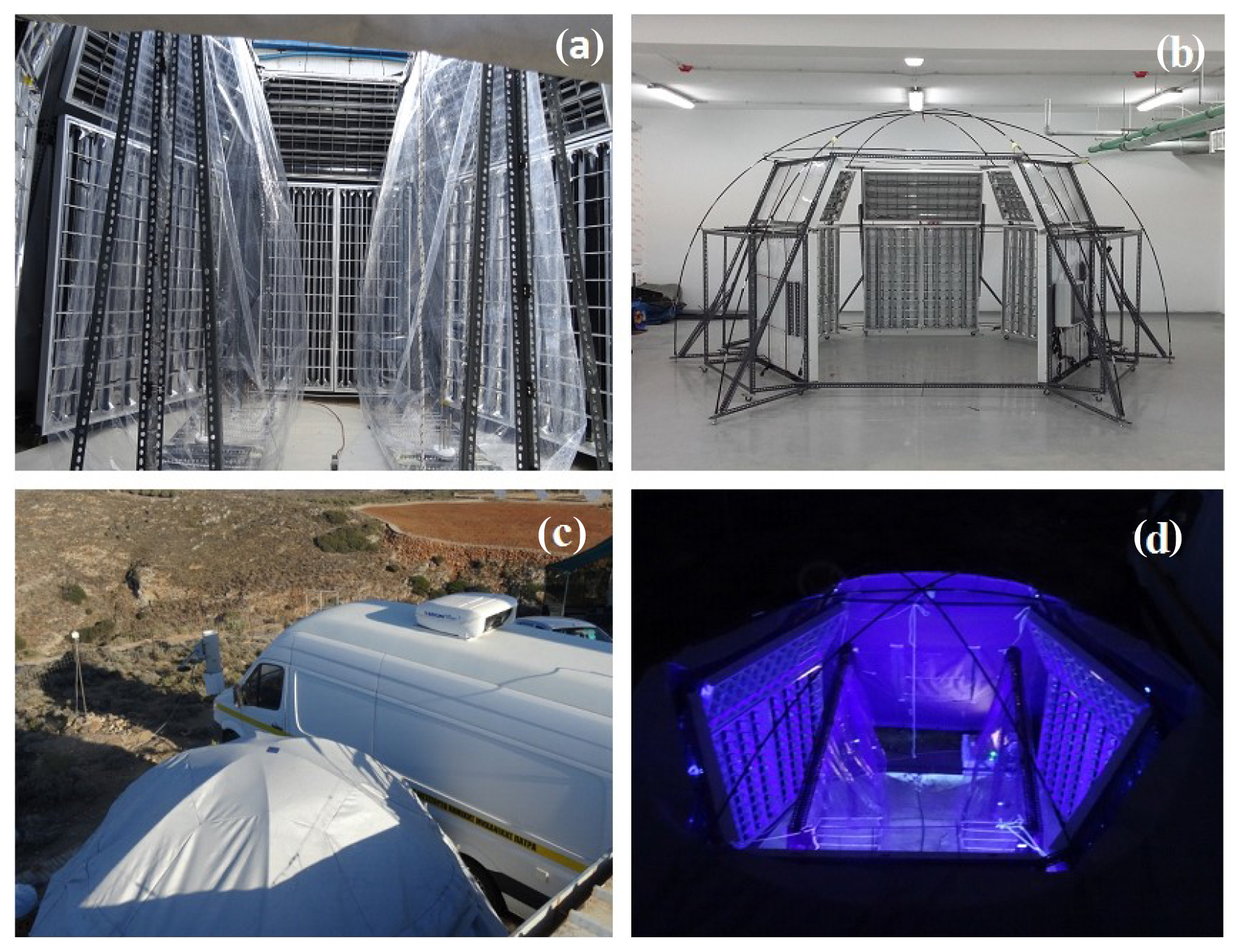
Figure 1Pictures of the portable dual-chamber system: (a) the dual chambers; (b) UV light assembly; (c) field deployment during the FAME 16 study; (d) system configuration with the UV lights on and the top cover open.
We constructed the chambers in our laboratory in Patras. The reactors were thoroughly cleaned and conditioned before the first characterization experiment. The cleaning procedure involved first introduction of high O3 concentrations with the UV lights on and heating to approximately 50 ∘C. Clean air was then passed through the chambers for several hours. Blank experiments were performed periodically in both the lab (during the characterization phase) and the field. The particle wall losses are measured after each field experiment. We did not observe any evolution of the wall chemical behavior in these initial tests.
Sampling is alternated between the two chambers every 3 min by an automated three-way valve synchronized with the operation of the corresponding instrumentation. This allows a total duration of the experiments of more than 4 h without the addition of makeup air. In order to eliminate interferences and memory effects due to this periodical alteration of the sampling lines, adequate time (30 s) is allowed within the 3 min sampling cycle for the lines to be flushed with the sample air from the next chamber. This is achieved by synchronizing the line flushing with the measuring instrumentation and discarding the data collected during this 30 s period.
2.2 Portable UV lighting system
A hemispheric design was selected with sixty 36 W UV light lamps (Osram, L36W/73) in a hexagonal arrangement. The lamps were mounted on five metal frames (12 per frame) creating five substructures (Fig. 1b) that can be easily disassembled and transported. Once assembled the UV light support structure had a footprint of 4.5 m×4.5 m and a height of 2.5 m. Figure 1b shows the UV light assembly without the covering material. Flexible tent poles were used to create a dome that can be partially or fully covered protecting the chambers from the weather elements (Fig. 1c and d). The sixth side does not include lights and is used as an entrance for chamber maintenance. The lights can be remotely operated at 20 %, 40 %, 60 %, 80 %, and 100 % levels. The light fixtures include aluminum mirrors in order to direct the light towards the center of the dome, thus maximizing the light intensity delivered to the chambers. When all lights are on, the corresponding is 0.1 min−1. The spectrum of the lights peaks in the 350–400 nm region (Fig. S1 in the Supplement). The two chambers are placed inside this dome having at least a 0.5 m clearance from the UV lights when full. This design also allows the use of a single 10 m3 chamber if so desired.
2.3 Subsystems
A dual-head metal bellows pump (model MB-602) is used to fill the chambers with ambient air delivering 80 L min−1 per pump head. Both chambers can be filled in around 20 min. Manual two-way valves were installed prior to the chamber inlets for isolation and selective filling purposes. Prior to any experiment with ambient air, both chambers are flushed with ambient air with the metal bellows pump until the NOx and O3 levels matched the ambient concentrations. To ensure chamber similarity the chambers are used alternatively in experiments as a perturbation/reference chamber.
If required clean particle-free air can be introduced in the chambers. Dry air is generated by an oilless compressor (Bambi VT200D) and further purified by activated carbon (carbon cap, Whatman), HEPA filters (HEPA capsule, Pall), and silica gel (silica gel rubin, Sigma-Aldrich). The compressor and air cleaning system are not used for the actual experiments. In these experiments the chambers are filled with ambient air without the use of cleaning devices. The compressor and cleaning system are used for the cleaning of the chambers between experiments and for blank or other chamber characterization experiments. Typically, the concentrations of ozone, NOx, and larger volatile organic compounds (VOCs) are below or close to the detection limit in the chambers when they are filled with clean air from our system. The scrubbers were replaced regularly and the residence time inside them was kept as high as possible (maintaining the corresponding flow rates as low as possible). The concentrations of some of the small oxygenated VOCs such as acetone, acetic acid, and methanol were slightly elevated compared to the cylinder zero air.
A subunit including the above systems (except for the filling pump and the compressor) was added to one of the metal frames of the system. This subunit also includes a syringe pump, an atomizer (TSI model 3076), and a silica gel diffusion drier (silica gel rubin, Sigma-Aldrich) for seed generation. Additionally, a bubbler subsystem for HONO introduction and an ozone generator (Azcozon, model HTU-500) were used. The concentration of OH when HONO was added was estimated in all experiments by the decay of d-butanol over time. The estimated levels of added HONO were of the order of 100 ppb. Two temperature and RH sensors (Omega, model RH-USB) and a personal computer with LabVIEW control for the sampling selection valve are also part of this system.
2.4 Instrumentation
The set of instruments selected for the use with the chamber system include a high-resolution time-of-flight mass spectrometer (HR-ToF-AMS, Aerodyne Research Inc.), a proton-transfer-reaction mass spectrometer (PTR-MS, Ionicon Analytik), a scanning mobility particle sizer (SMPS, classifier model 3080, DMA model 3081, CPC model 3787, TSI), an ozone monitor (API Teledyne, model 400E), and a NOx monitor (API Teledyne, model T201). These instruments are located inside the FORTH mobile laboratory (Fig. 1c) next to the chambers. Details on the instrumentation used can be found elsewhere (Kostenidou et al., 2013; Kaltsonoudis et al., 2017). With this configuration, a total sampling flow rate of 2.5–3 L min−1 is used that removes less than 0.1 m3 from each chamber per hour.
2.5 Experimental procedure
The instrumentation is first used to characterize the ambient conditions for at least a couple of hours. After filling of the chambers is completed, sampling is switched from ambient measurements to the chambers and an initial characterization of the sampled air inside the chambers takes place. Then a perturbation (addition of oxidant or pollutant) is implemented in one of the chambers, while the other is used as a reference. Following the completion of the experiment, ammonium sulfate seeds are introduced into both chambers to measure their loss rate on the walls over time. In this step, the chambers may be refilled with particle-free air. This last stage is used to quantify the particle-size-dependent wall loss rate constants in order to make corrections to the rest of the measurements. Finally, the instrumentation is switched back to ambient observations and the chambers are flushed with either ambient air and/or clean air in preparation for the next experiment.
The system was developed and evaluated in Patras, Greece, and also during the Finokalia Aerosol Measurement Experiment (FAME 16) campaign. Finokalia is a remote site in Crete, Greece (Kouvarakis et al., 2000). The field campaign took place during May–June 2016. Additional tests aimed at improving the performance of the setup were performed indoors at Carnegie Mellon University in Pittsburgh, United States. The present work is based on the results of 51 chamber characterization experiments and seven field test experiments. The characterization experiments include 15 blank or contamination-related experiments, 14 experiments characterizing wall losses, six experiments quantifying the ambient air sampling efficiency, three experiments for the measurement of , nine experiments related to RH and UV variations, and four VOC loss experiments. The list of these experiments and some additional information can be found in Table S1 in the Supplement.
3.1 Contamination tests
Tests were conducted in the field in order to assess the potential contamination of the chambers by ambient air. The chambers were filled with clean (particle free) air and the particle concentration inside the chambers was monitored by an SMPS. Figure 2 shows the total number concentrations in the two chambers. The particle number concentrations remained below 10 cm−3 in both chambers for several hours. The aerosol mass concentration (not shown) was less than 0.01 µg m−3. This suggests that clean conditions can be maintained for both chambers for the duration of a typical field experiment.
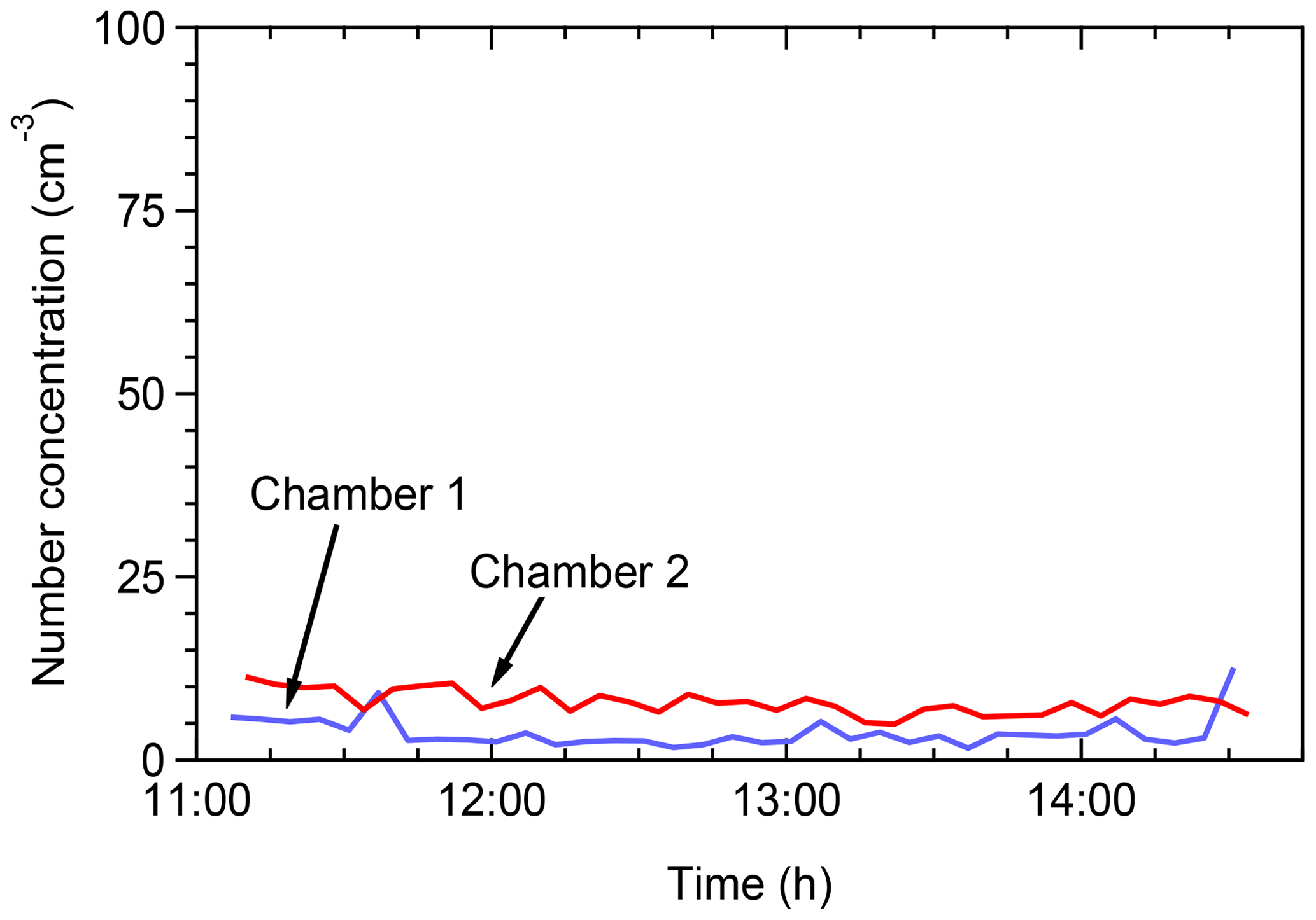
Figure 2Total particle number concentrations as a function of time when the chambers were filled with clear air in the field for leak check of the chambers.
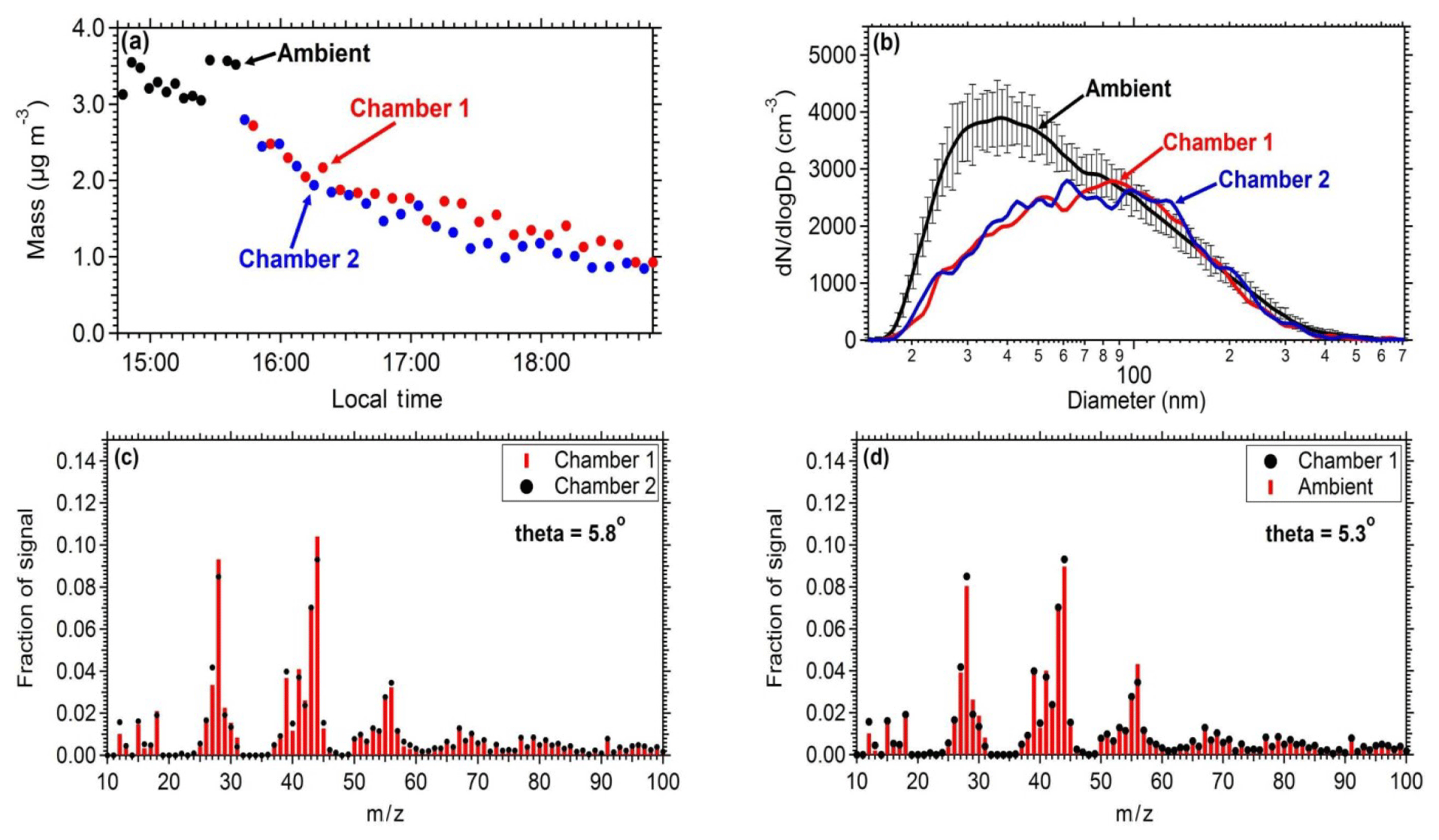
Figure 3Comparison of the measurements between the two chambers and between ambient measurements: (a) mass concentration (PM0.7) as measured by the SMPS in both the chambers and the ambient air. (b) Number distributions inside the chambers and in the ambient air (the error bar represents 1 standard deviation). (c) Average aerosol mass spectra of chamber 1 and chamber 2 filled with ambient air. (d) Average aerosol mass spectra of ambient air and chamber 1.
3.2 Chamber similarity
Similar results should be obtained when identical experiments take place in the two chambers in order to safely use one of them as reference. To establish this, ambient air was introduced in both chambers and the evolution of the concentrations and composition of the particulate matter and gas pollutants was measured. An SMPS measured the size distribution and an AMS the particulate composition. The measured chamber and ambient mass concentrations (Fig. 3a) and the AMS spectra (Fig. 3c and d) were in good agreement between the two chambers and the ambient air. The particle mass concentration in the chambers was approximately 85 % of the ambient levels. The theta angle (Kostenidou et al., 2009) between the organic aerosol spectra in the two chambers and the ambient air was in the range of 2.5–6∘, suggesting that identical results can be obtained when filling these chambers with ambient air and that the filling process does not contaminate the air sample. The theta angle is a measure of the similarity of the OA spectra (similar to the often used R2). Each mass spectrum is treated as a vector (each m∕z is an element of the vector) and theta is the angle between two such vectors. We prefer to use the theta angle for AMS spectra comparisons because it can better distinguish small differences in spectra that the coefficient of determination cannot.
Pump and tubing losses during the filling procedure were evaluated in order to establish the difference between ambient concentrations and the ones obtained in the chambers. The same number distributions are achieved in both chambers after filling them with ambient air. The penetration efficiency through the tubing and the pump for particles with diameter larger than 80 nm is close to 100 %, while for smaller particles due to higher diffusional deposition the penetration efficiency is 45 %. The length of the tubing is approximately 1 m (with a 0.5 in diameter). The estimated losses for this tube for the flow rates used and for particles in the 20–80 nm size range are 1 %–3 %. Therefore, most of the losses occur in the pump.
3.3 Particle wall losses
Loss of particles to the walls is one of the processes that complicates the analysis of smog chamber experiments. The use of smaller reactors with lower surface-to-volume ratios can accelerate these losses. Disturbances of the Teflon reactors tend to increase the wall loss rates due to the buildup of static charges on the chamber walls. Transporting and installing the reactors also results in higher wall loss rate constants (Wang et al., 2018).

Figure 4Coagulation-corrected particle wall loss rate constant as a function of particle size for the two chambers (a) in the laboratory and (b) in the field. The particle wall loss rate constant as a function of particle size during 3 consecutive days for the field deployment. Panel (c) corresponds to chamber 1 and (d) to chamber 2.
In order to assess the wall loss behavior of the system, experiments were conducted in both the laboratory and the field. In all cases, ammonium sulfate seeds were added to the chambers and their decay with time was measured. Typically, the chambers were first filled with clean (particle-free) air and then ammonium sulfate seeds were introduced. A solution of 5 g L−1 ammonium sulfate was used for the atomizer and a flow rate of 2 L min−1. The decay of the particles was monitored by an SMPS. Size-dependent wall loss rate constants were calculated correcting for coagulation (Wang et al., 2018). Figure 4a represents the average size-dependent profiles for the loss rate constant Kc of the two chambers for the laboratory experiments. On the field, higher rate loss constants were measured (Fig. 4b). For example, loss rate constants of 0.2 h−1 were measured for the 350 nm particles in the lab, while for the same size range, a value of approximately 0.5 h−1 was measured in the field. Figure 4c and d show the wall loss profiles of the two chambers when deployed in the Finokalia campaign over 3 d of measurements. In both chambers the wall loss rate constants decreased over time. During the field deployment of the chambers their handling and the corresponding induced friction resulted in higher charges on the chamber walls and thus higher particle wall losses. These higher losses had also a stronger size dependence. Conversely, when the chambers were inside the lab, there was no buildup of charges and the losses were lower and less size-dependent. A detailed analysis of the losses of particles in Teflon chambers (both in the laboratory and the field) has been presented by Wang et al. (2018). For this reason, the particle wall loss rates are measured after each experiment, by the addition of ammonium sulfate seeds. The chambers in the laboratory underwent minimum handling during each experiment and thus achieved low loss rate constants for a wide range of particle sizes.
In order to assess if it is possible to minimize such charges, a test was conducted in the Teflon reactors in the lab. The chambers were moved in a different location inside the building where the lab is located. The two reactors were handled in exactly the same way simulating the handling during a field deployment. One of the chambers was inflated with air to almost half full while the other was empty. The particle wall losses were measured before and after the movement. Figure 5 represents the loss rate constants in the two chambers because of the movement. The loss rate did not change in the partially inflated chamber. The other chamber, though, experienced an increase in the loss rate constants, almost doubling for the particles in the range 50–200 nm, due to stronger friction of the Teflon walls with each other and thus building static charge. No significant change was noticed for particles larger than 250 nm.

Figure 5Coagulation-corrected particle wall loss rate constant as a function of particle size for the two chambers after the movement (a) in the partially inflated chamber and (b) in the deflated chamber. The error bars represent 1 standard deviation.
The high particle wall losses introduce uncertainty in the results because the wall loss corrections dominate the corrected concentration values. If the losses are very high, the maximum duration of such experiments may be limited. We have been working on developing methods to minimize these effects. Moving the chambers to the field site either fully or at least partially inflated inside our mobile laboratory clearly helps.
3.4 VOC concentrations
Concentrations of the VOCs measured by the PTR-MS were within a few percent of their ambient levels. In most cases, no noticeable differences were seen. Tests indicated that there was no detectable contamination due to the metal bellows pump during the filling process of the two chambers. Vapor loss experiments were also performed for a few selected VOCs. The measured wall loss rates were quite low (less than 1 % h−1) for toluene and α-pinene. Their concentrations remained for all practical purposes stable during the experiment.
3.5 NOx, O3, and OH interactions with the walls
A series of experiments were performed to quantify the loss rates of NOx and O3 to the Teflon walls of the chambers and the OH production rates. These can be used for the development of an auxiliary mechanism. The experiments were carried out for two light intensities ( of 0.03 and 0.1 min−1) and for two RH values (RH <10 % and 50±15 %). The OH levels in the chamber were estimated based on the decay of d-butanol. HONO off-gassing from the chamber walls was not measured directly, but was estimated based on the OH levels. Effective OH production rates were estimated using a pseudo-steady-state assumption. The OH production rates were practically negligible at low RH, but increased at 50 % RH and depended on light intensity. The results of these measurements can be found in the Supplement. These measurements indicate that the HONO injections were the dominant source of OH in our perturbation experiments. However, the contribution of the walls can be non-negligible under some conditions for the baseline chamber. To minimize complications, d-butanol was injected in all experiments, allowing the direct estimation of the OH concentration in both chambers. As a result the reported OH exposure takes into account the wall sources as well.
The performance of the system was tested in experiments that took place indoors at Carnegie Mellon University (Center for Atmospheric Particle Studies). The potential aging of urban background air masses in Pittsburgh, PA, by OH radicals was used as a pilot study for the system evaluation. Fewer UV lights were used in this test, resulting in a equal to 0.03 min−1.
4.1 Experimental procedure
Prior to the experiment, both chambers were flushed with particle-free air overnight under UV illumination to remove any residual particles and gas-phase organics. Both chambers were filled with ambient air using the metal bellows pump. During the filling procedure, the instruments measured ambient conditions. After the addition of ambient air in the chambers, d-butanol (60 ppb) was added to both of them as an OH tracer (Barmet et al., 2012). The OH levels can be estimated by the decay in the d-butanol concentration measured by the PTR-MS system at m∕z 66. The reaction constant for the butanol reaction with OH is 3.4×1012 cm3 molecules−1 s−1. HONO was injected only into the perturbation chamber for about 3 min to produce OH upon UV illumination. The UV lights were then turned on to illuminate both chambers. After the completion of the perturbation experiment, a seed wall loss experiment was conducted to quantify the particle wall loss rate constants for the two chambers as described in Sect. 3.3.
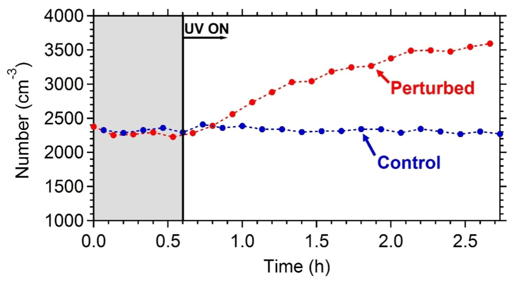
Figure 6The wall-loss-corrected SMPS-measured aerosol number concentration. HONO was added only in the perturbed chamber at t=0.4 h to produce OH under UV illumination. The shaded area indicates that the chambers were dark.
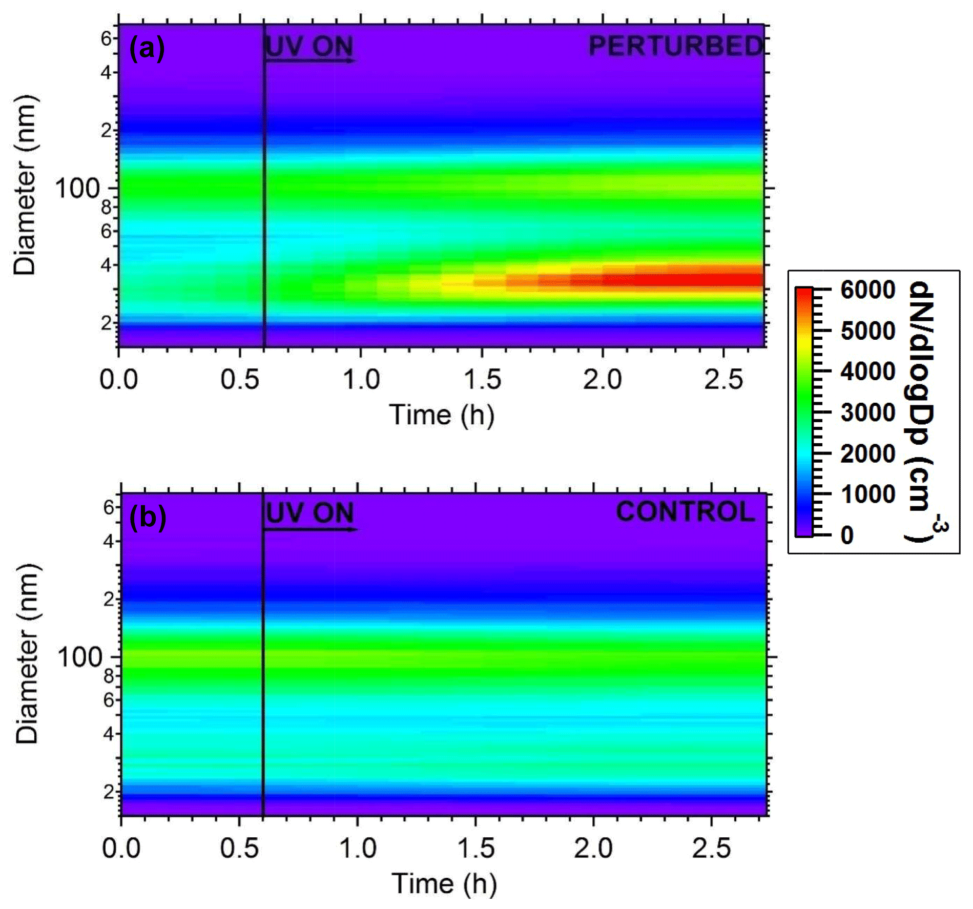
Figure 7Plots of the evolution of particle number distributions during the HONO perturbation experiment in Pittsburgh. (a) Perturbed chamber and (b) control chamber.
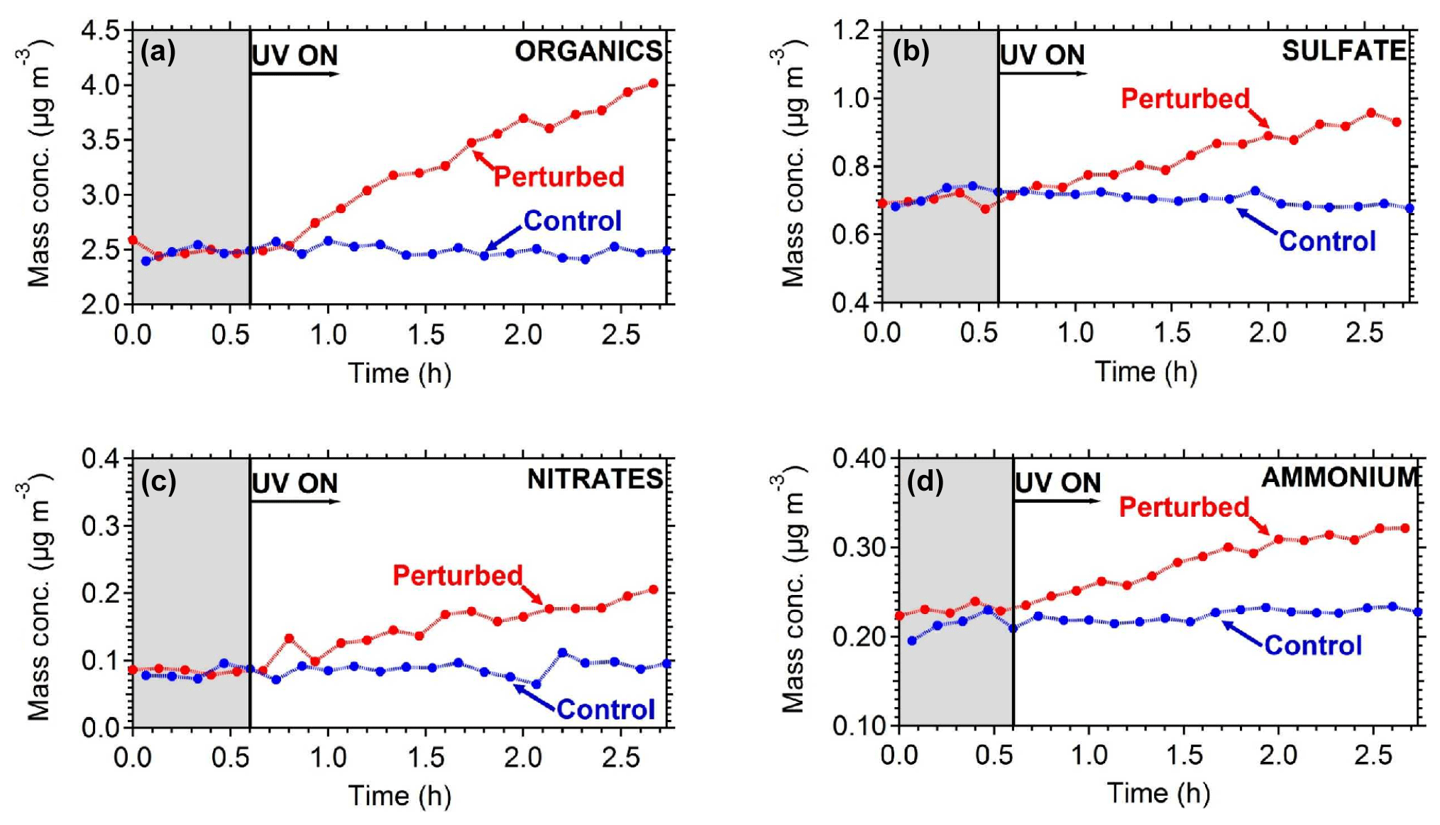
Figure 8The particle wall-loss-corrected concentrations of the major PM1 components measured by the AMS (a) organics, (b) sulfate, (c) nitrates, and (d) ammonium. The shaded area indicates that the chambers were dark. Data have been corrected for the collection efficiency (CE = 0.6).
4.2 Results and discussion
The wall-loss-corrected total particle number concentration as measured by the SMPS is shown in Fig. 6. The instruments measured ambient conditions during the filling process. The average ambient number concentration was around 2500 cm−3. HONO was injected in the perturbed chamber at t=0.4 h. After turning on the UV lights (t=0.6 h) an increase in the total particle number and volume in the perturbed chamber was observed while no change in the control chamber was noticed. The increase in the perturbed chamber is due to the formation of new particles (Fig. 7).
Based on the AMS measurements, the ambient air used to fill the chambers contained on average 3.6 µg m−3 of non-refractory PM1 with organics accounting for 75 %, sulfate 17 %, ammonium 6 %, and nitrate 2 %. The collection efficiency of the AMS measurements was found to be 0.6 based on the algorithm of Kostenidou et al. (2007), while the estimated OA density was 1.2 g cm−3. The calculated theta angle (Kostenidou et al., 2009) between the ambient and the chamber organic mass spectra vectors was around 5∘, indicating that the aerosol composition inside the chamber was essentially the same as in the ambient air.
To quantify the secondary aerosol formation, data were corrected for both the collection efficiency and for particle wall losses. Figure 8 shows the concentrations of the major PM1 components in the two chambers. An increase in concentration was observed in the perturbed chamber. After 2.5 h of exposure to OH an additional 1.5 µg m−3 of organics, 0.2 µg m−3 of sulfates, 0.1 µg m−3 of nitrates, and 0.1 µg m−3 of ammonium were formed. The average OH concentration in the perturbed chambers was 8.0×10⁶ molecules cm−3 corresponding to approximately 11 h of equivalent exposure to an ambient molecules cm−3. The OH concentration in the control chamber was an order of magnitude less 8×10⁵ molecules cm−3. The organic spectra of the additional formed secondary organic aerosol (SOA) and the initial OA in the perturbed chamber were relatively similar; their theta angle was 10∘ (Fig. 9). The mass spectrum of the processed OA was characterized by lower fractional contributions at m∕z 43 and 44.

Figure 9The organic mass spectra after filling and after 2 h of UV illumination in the perturbed chamber.
The evolution of the oxygen-to-carbon ratio of the organic aerosol in the two chambers is shown in Fig. 10. The O : C of the ambient organic aerosol and of the initial OA in the two chambers was 0.44. After the OH introduction and the SOA production in the perturbed chamber, the O : C decreased slightly to 0.40. The O : C in the control chamber remained approximately the same. The decrease in the O : C in the perturbed chamber indicates that the additional formed SOA had smaller O : C than the ambient air. The average O : C ratio in other ambient experiments conducted in Pittsburgh was around 0.5, indicating an already moderately oxidized aerosol population. For comparison, the average O : C ratio in the FAME 2008 and FAME 2009 campaigns was 0.8 and 0.5, respectively (Hildebrandt et al., 2010). The results of such ambient air experiments with detailed analysis of the formed aerosol and comparison with ambient and laboratory measurements are included in a forthcoming publication.
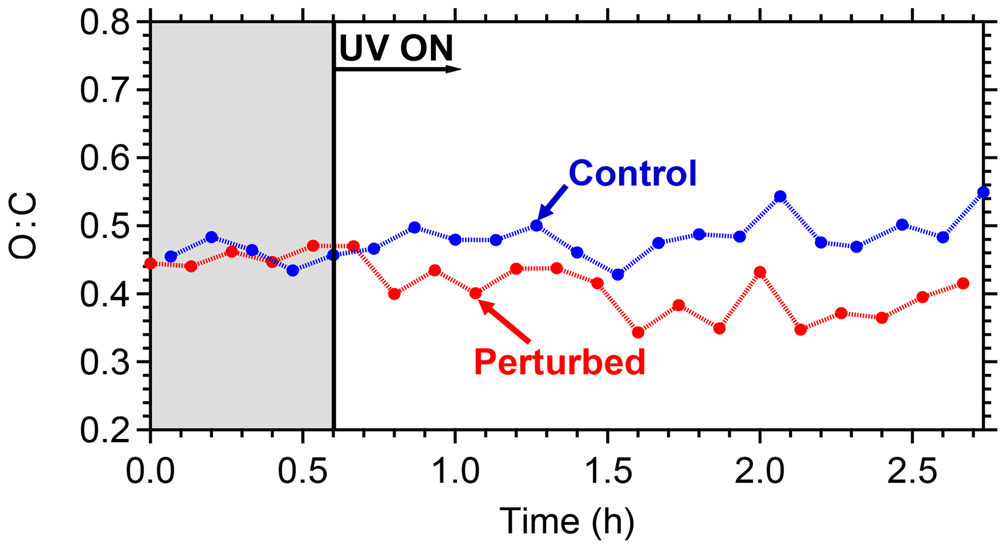
Figure 10The O : C ratio evolution for the control and the perturbed chamber. The shaded area indicates that the chambers were in the dark.
A portable dual-chamber system has been developed for field studies using ambient air as a starting point. The system has been evaluated and no contamination was observed during a typical experiment. The concentrations in the two chambers when filled with ambient air are within a few percent of each other. Particle losses during filling were less than 20 %. No noticeable losses or cross-contamination was observed for the measured VOC species.
Higher wall loss rates were observed when the chambers were deployed in the field, compared to the lower and stable rates observed when the chambers were inside the laboratory, due to higher electrostatic charges induced during their movement. A reduction in the wall loss rates with time was observed when the chambers were deployed in the field, suggesting that they should be measured after each experiment. The losses can be reduced if the chambers are transported partially inflated. Initial laboratory experiments show promising results with respect to potential aging properties of urban background air in Pittsburgh. An additional 1.5 µg m−3 of SOA was formed after 12 h of equivalent OH exposure with a moderate decrease in the O : C ratio. Implementing the system in the field will enable the study of complex systems that were previously out of reach with traditional stationary chamber facilities.
The data in the study are available from the authors upon request (spyros@chemeng.upatras.gr).
The supplement related to this article is available online at: https://doi.org/10.5194/amt-12-2733-2019-supplement.
CK constructed the facility, participated in the experiments, and wrote the paper. SDJ conducted and analyzed the wall loss and test experiments and contributed to the writing of the paper. EL and KF helped in the construction of the facility and assisted in the experiments. SNP was responsible for the design of the study and the synthesis of the results and contributed to the writing of the paper.
The authors declare that they have no conflict of interest.
This article is part of the special issue “Simulation chambers as tools in atmospheric research (AMT/ACP/GMD inter-journal SI)”. It is not associated with a conference.
This research was supported by the European Research Council Project ATMOPACS (Atmospheric Organic Particulate Matter, Air Quality and Climate Change Studies) (grant agreement 267099). This work has also received funding from the European Union's Horizon 2020 research and innovation program through the EUROCHAMP-2020 Infrastructure Activity under grant agreement no. 730997.
This paper was edited by Hartmut Herrmann and reviewed by two anonymous referees.
Akimoto, H., Hishino, M., Inoue, G., Sakaaki, F., Washida, N., and Okuda, M.: Design and characterization of the evacuable and bankable photochemical smog chamber, Environ. Sci. Technol., 13, 471–475, 1979.
Akimoto, H., Takagi, H., and Sakamaki, F.: Photo enhancement of nitrous acid formation in the surface reaction of nitrogen dioxide and water vapor: Extra radicals source in smog chamber experiments, Int. J. Chem. Kinet., 19, 539–551, 1987.
Barmet, P., Dommen, J., DeCarlo, P. F., Tritscher, T., Praplan, A. P., Platt, S. M., Prévôt, A. S. H., Donahue, N. M., and Baltensperger, U.: OH clock determination by proton transfer reaction mass spectrometry at an environmental chamber, Atmos. Meas. Tech., 5, 647–656, https://doi.org/10.5194/amt-5-647-2012, 2012.
Bloss, C., Wagner, V., Bonzanini, A., Jenkin, M. E., Wirtz, K., Martin-Reviejo, M., and Pilling, M. J.: Evaluation of detailed aromatic mechanisms (MCMv3 and MCMv3.1) against environmental chamber data, Atmos. Chem. Phys., 5, 623–639, https://doi.org/10.5194/acp-5-623-2005, 2005.
Carter, W. P. L., Atkinson, R., Winer, A. M., and Pitts Jr., J. N.: Experimental investigation of chamber dependent radical sources, Int. J. Chem. Kinet., 14, 1071–1103, 1982.
Carter, W. P. L., Cocker, D. R., Fitz, D. R., Malkina, I. L., Bumiller, K., Sauer, C. G., Pisano, J. T., Bufalino, C., and Song, C.: A new environmental chamber for evaluation of gas-phase chemical mechanisms and secondary aerosol formation, Atmos. Environ., 39, 7768–7788, 2005.
Cocker, D. R., Flagan, R. C., and Seinfeld, J. H.: State-of-the-art chamber facility for studying atmospheric aerosol chemistry, Environ. Sci. Technol., 35, 2594–2601, 2001a.
Cocker D. R., Clegg, S. L., Flagan, R. C., and Seinfeld, J. H.: The effect of water on gas–particle partitioning of secondary organic aerosol. Part I: α-pinene/ozone system, Atmos. Environ., 35, 6049–6072, 2001b.
Finlayson, B. and Pitts, J. N.: Photochemistry of the polluted troposphere, Science, 192, 111–119, 1976.
Finlayson-Pitts, B. J., Wingen, L. M., Summer, A. L., Syomin, D., and Ramazan, K. A.: The heterogeneous hydrolysis of NO2 in laboratory systems and in outdoor and indoor atmospheres: An integrated mechanism, Phys. Chem. Chem. Phys., 5, 223–242, 2003.
Glasson, W. A. and Dunker, A. M.: Investigation of background radical sources in Teflon-film irradiation chamber, Environ. Sci. Technol., 23, 970–978, 1989.
Hallquist, M., Wenger, J. C., Baltensperger, U., Rudich, Y., Simpson, D., Claeys, M., Dommen, J., Donahue, N. M., George, C., Goldstein, A. H., Hamilton, J. F., Herrmann, H., Hoffmann, T., Iinuma, Y., Jang, M., Jenkin, M. E., Jimenez, J. L., Kiendler-Scharr, A., Maenhaut, W., McFiggans, G., Mentel, Th. F., Monod, A., Prévôt, A. S. H., Seinfeld, J. H., Surratt, J. D., Szmigielski, R., and Wildt, J.: The formation, properties and impact of secondary organic aerosol: current and emerging issues, Atmos. Chem. Phys., 9, 5155–5236, https://doi.org/10.5194/acp-9-5155-2009, 2009.
Heisler, S. L. and Friedlander, S. K.: Gas to particle conversion in photochemical smog: Aerosol growth laws and mechanisms for organics, Atmos. Environ., 11, 157–168, 1977.
Hennigan, C. J., Miracolo, M. A., Engelhart, G. J., May, A. A., Presto, A. A., Lee, T., Sullivan, A. P., McMeeking, G. R., Coe, H., Wold, C. E., Hao, W.-M., Gilman, J. B., Kuster, W. C., de Gouw, J., Schichtel, B. A., Collett Jr., J. L., Kreidenweis, S. M., and Robinson, A. L.: Chemical and physical transformations of organic aerosol from the photo-oxidation of open biomass burning emissions in an environmental chamber, Atmos. Chem. Phys., 11, 7669–7686, https://doi.org/10.5194/acp-11-7669-2011, 2011.
Hildebrandt, L., Kostenidou, E., Mihalopoulos, N., Worsnop, D. R., Donahue, N. M., and Pandis, S. N.: Formation of highly oxygenated organic aerosol in the atmosphere: Insights from the Finokalia Aerosol Measurement Experiments, Geophys. Res. Lett.,37, L23801, https://doi.org/10.1029/2010GL045193, 2010.
Hynes, R. G., Angove, D. E., Saunders, S. M., Haverd, V., and Azzi, M.: Evaluation of two MCM v3.1 alkene mechanisms using indoor environmental chamber data, Atmos. Environ., 39, 7251–7262, 2005.
Jeffries, H., Fox, D., and Kamens, R.: Outdoor smog chamber studies: light effects relative to indoor chambers, Environ. Sci. Technol., 10, 1006–1011, 1976.
Jenkin, M. E., Cox, R. A., and Williams, D. J.: Laboratory studies of the kinetics of formation of nitrous acid from the thermal reaction of nitrogen dioxide and water vapor, Atmos. Environ., 22, 487–498, 1988.
Kaltsonoudis, C., Kostenidou, E., Louvaris, E., Psichoudaki, M., Tsiligiannis, E., Florou, K., Liangou, A., and Pandis, S. N.: Characterization of fresh and aged organic aerosol emissions from meat charbroiling, Atmos. Chem. Phys., 17, 7143–7155, https://doi.org/10.5194/acp-17-7143-2017, 2017.
Kelly, N. A.: The photochemical formation and fate of nitric acid in the metropolitan Detroit area: Ambient, captive-air irradiation and modeling results, Atmos. Environ., 21, 2163–2177, 1987.
Kelly, N. A. and Gunst, R. F.: Response of ozone to changes in hydrocarbon and nitrogen oxide concentrations in outdoor smog chambers filled with Los Angeles air, Atmos. Environ., 24, 2991–3005, 1990.
Killus, J. P. and Whitten, G. Z.: Background reactivity in smog chambers, Int. J. Chem. Kinet., 22, 547–575, 1990.
Kim, Y. J., Platt, U., Gu, M. B., and Iwahashi, H.: Atmospheric and biological environmental monitoring, Springer, Dordrecht, the Netherlands, 2009.
Kleffmann, J., Becker, K. H., and Wiesen, P.: Heterogeneous NO2 conversion processes on acid surfaces: Possible atmospheric implications, Atmos. Environ., 32, 2721–2729, 1998.
Kostenidou, E., Pathak, R. K., and Pandis, S. N.: An algorithm for the calculation of secondary organic aerosol density combining AMS and SMPS data, Aerosol Sci. Tech., 41, 1002–1010, 2007.
Kostenidou, E., Lee, B. H., Engelhart, G. J., Pierce, J. R., and Pandis, S. N.: Mass spectra deconvolution of low, medium and high volatility biogenic secondary organic aerosol, Environ. Sci. Technol., 43, 4884–4889, 2009.
Kostenidou, E., Kaltsonoudis, C., Tsiflikiotou, M., Louvaris, E., Russell, L. M., and Pandis, S. N.: Burning of olive tree branches: a major organic aerosol source in the Mediterranean, Atmos. Chem. Phys., 13, 8797–8811, https://doi.org/10.5194/acp-13-8797-2013, 2013.
Kouvarakis, G., Tsigaridis, K., Kanakidou, M., and Mihalopoulos, N.: Temporal variations of surface background ozone over Crete island in the southeast Mediterranean, J. Geophys. Res., 105, 4399–4407, 2000.
Laity, J.: A smog chamber study comparing black light fluorescent lamps with natural sunlight, Environ. Sci. Technol., 5, 1218–1220, 1971.
Lee, B. S., Bae, G. N., Moon, K. C., and Choi, M.: Correlation between light Intensity and ozone formation for photochemical smog in urban air of Seoul, Aerosol Air Qual. Res., 10, 540–549, 2010.
Leone, J. A., Flagan, R. C., Grosjean, D., and Seinfeld, J. H.: An outdoor smog chamber and modeling study of toluene–NOx photooxidation, Int. J. Chem. Kinetics, 17, 177–216, 1985.
Metzger, A., Dommen, J., Gaeggeler, K., Duplissy, J., Prevot, A. S. H., Kleffmann, J., Elshorbany, Y., Wisthaler, A., and Baltensperger, U.: Evaluation of 1,3,5 trimethylbenzene degradation in the detailed tropospheric chemistry mechanism, MCMv3.1, using environmental chamber data, Atmos. Chem. Phys., 8, 6453–6468, https://doi.org/10.5194/acp-8-6453-2008, 2008.
Ortega, A. M., Hayes, P. L., Peng, Z., Palm, B. B., Hu, W., Day, D. A., Li, R., Cubison, M. J., Brune, W. H., Graus, M., Warneke, C., Gilman, J. B., Kuster, W. C., de Gouw, J., Gutiérrez-Montes, C., and Jimenez, J. L.: Real-time measurements of secondary organic aerosol formation and aging from ambient air in an oxidation flow reactor in the Los Angeles area, Atmos. Chem. Phys., 16, 7411–7433, https://doi.org/10.5194/acp-16-7411-2016, 2016.
Paulsen, D., Dommen, J., Kalberer, M., Prevot, A. S. H., Richter R., Sax, M., Steinbacher, M., Weingartner, E., and Baltensperger, U.: Secondary organic aerosol formation by irradiation of 1,3,5-trimethylbenzene-NOx-H2O in a new reaction chamber for atmospheric chemistry and physics, Environ. Sci. Technol., 39, 2668–2678, 2005.
Pitts, J. N., Smith, J. P., Fitz, D. R., and Grosjean, D.: Enhancement of photochemical smog by N,N-diethylhydroxylamine in polluted ambient air, Science, 197, 255–257, 1977.
Pitts, J. N., Sanhueza, E., Atkinson, R., Carter, W. P. L., Winer, A. M., Harris, G. W., and Plum, C. N.: An investigation of nitrous acid in environmental chambers, Int. J. Chem. Kinet., 16, 919–939, 1984.
Platt, S. M., El Haddad, I., Zardini, A. A., Clairotte, M., Astorga, C., Wolf, R., Slowik, J. G., Temime-Roussel, B., Marchand, N., Ježek, I., Drinovec, L., Mocnik, G., Möhler, O., Richter, R., Barmet, P., Bianchi, F., Baltensperger, U., and Prévôt, A. S. H.: Secondary organic aerosol formation from gasoline vehicle emissions in a new mobile environmental reaction chamber, Atmos. Chem. Phys., 13, 9141–9158, https://doi.org/10.5194/acp-13-9141-2013, 2013.
Roberts, P. T. and Friedlander, S. K.: Photochemical aerosol formation. SO2, 1-heptene, and NO, in ambient air, Environ. Sci. Technol., 10, 573–580, 1976.
Rohrer, F., Bohn, B., Brauers, T., Brüning, D., Johnen, F.-J., Wahner, A., and Kleffmann, J.: Characterisation of the photolytic HONO-source in the atmosphere simulation chamber SAPHIR, Atmos. Chem. Phys., 5, 2189–2201, https://doi.org/10.5194/acp-5-2189-2005, 2005.
Sakamaki, F. and Akimoto, H.: HONO formation as unknown radical source in photochemical smog chamber, Int. J. Chem. Kinet., 20, 111–116, 1988.
Sakamaki, F., Hatakeyama, S., and Akimoto, H.: Formations of nitrous acid and nitric oxide in the heterogeneous reaction of nitrogen dioxide and water vapor in a smog chamber, Int. J. Chem. Kinet., 15, 1013–1029, 1983.
Shibuya, K. and Nagashima, T.: Photochemical ozone formation in the irradiation of ambient air samples by using a mobile smog chamber, Environ. Sci. Technol., 6, 661–665, 1981.
Stockwell, C. E., Yokelson, R. J., Kreidenweis, S. M., Robinson, A. L., DeMott, P. J., Sullivan, R. C., Reardon, J., Ryan, K. C., Griffith, D. W. T., and Stevens, L.: Trace gas emissions from combustion of peat, crop residue, domestic biofuels, grasses, and other fuels: configuration and Fourier transform infrared (FTIR) component of the fourth Fire Lab at Missoula Experiment (FLAME-4), Atmos. Chem. Phys., 14, 9727–9754, https://doi.org/10.5194/acp-14-9727-2014, 2014.
Svensson, R., Ljungstrom, E., and Lindqvist, O.: Kinetics of the reaction between nitrogen dioxide and water, Atmos. Environ., 21, 1529–1539, 1987.
Tkacik, D. S., Lambe, A. T., Jathar, S., Li, X., Presto, A. A., Zhao, Y., Blake, D. R., Meinardi, S., Jayne, J. T., Croteau, P. L., and Robinson, A. L.: Secondary organic aerosol formation from in-use motor vehicle emissions using a potential aerosol mass reactor, Environ. Sci. Technol., 48, 11235–11242, 2014.
Tritscher, T., Dommen, J., DeCarlo, P. F., Gysel, M., Barmet, P. B., Praplan, A. P., Weingartner, E., Prévôt, A. S. H., Riipinen, I., Donahue, N. M., and Baltensperger, U.: Volatility and hygroscopicity of aging secondary organic aerosol in a smog chamber, Atmos. Chem. Phys., 11, 11477–11496, https://doi.org/10.5194/acp-11-11477-2011, 2011.
Wang, J., Doussin, J. F., Perrier, S., Perraudin, E., Katrib, Y., Pangui, E., and Picquet-Varrault, B.: Design of a new multi-phase experimental simulation chamber for atmospheric photosmog, aerosol and cloud chemistry research, Atmos. Meas. Tech., 4, 2465–2494, https://doi.org/10.5194/amt-4-2465-2011, 2011.
Wang, N., Jorga, S. D., Pierce, J. R., Donahue, N. M., and Pandis, S. N.: Particle wall-loss correction methods in smog chamber experiments, Atmos. Meas. Tech., 11, 6577–6588, https://doi.org/10.5194/amt-11-6577-2018, 2018.
Wang, X., Liu, T., Bernard, F., Ding, X., Wen, S., Zhang, Y., Zhang, Z., He, Q., Lü, S., Chen, J., Saunders, S., and Yu, J.: Design and characterization of a smog chamber for studying gas-phase chemical mechanisms and aerosol formation, Atmos. Meas. Tech., 7, 301–313, https://doi.org/10.5194/amt-7-301-2014, 2014.
Warren, B., Song, C., and Cocker, D. R.: Light intensity and light source influence on secondary organic aerosol formation for the m-xylene/NOx photooxidation system, Environ. Sci. Technol., 42, 5461–5466, 2008.
Weitkamp, E. A., Sage, A. M., Pierce, J. R., Donahue, N. M., and Robinson, A. L.: Organic aerosol formation from photochemical oxidation of diesel exhaust in a smog chamber, Environ. Sci. Technol., 410, 6969–6975, 2007.