the Creative Commons Attribution 4.0 License.
the Creative Commons Attribution 4.0 License.
 | 12 Oct 2022
The realization of autonomous, aircraft-based, real-time aerosol mass spectrometry in the upper troposphere and lower stratosphere
Sergej Molleker
Oliver Appel
Andreas Hünig
Thomas Böttger
Markus Hermann
Frank Drewnick
Johannes Schneider
Ralf Weigel
Stephan Borrmann
We report on the developments that enabled the field deployment of a fully automated aerosol mass spectrometer, especially designed for high-altitude measurements on unpressurized aircraft. The merits of the two main categories of real-time aerosol mass spectrometry, i.e. (a) single-particle laser desorption and ionization and (b) continuous thermal desorption and electron impact ionization of aerosols, have been integrated into one compact apparatus with the aim to perform in situ real-time analysis of aerosol chemical composition. The demonstrated instrument, named the ERICA (European Research Council Instrument for Chemical composition of Aerosols), operated successfully aboard the high-altitude research aircraft M-55 Geophysica at altitudes up to 20 km while being exposed to ambient conditions of very low atmospheric pressure and temperature. A primary goal of those field deployments was the in situ study of the Asian tropopause aerosol layer (ATAL). During 11 research flights, the instrument operated for more than 49 h and collected chemical composition information of more than 150 000 single particles combined with quantitative chemical composition analysis of aerosol particle ensembles. This paper presents in detail the technical characteristics of the main constituent parts of the instrument, as well as the design considerations for its integration into the aircraft and its autonomous operation in the upper troposphere and lower stratosphere (UTLS). Additionally, system performance data from the first field deployments of the instrument are presented and discussed, together with exemplary mass spectrometry data collected during those flights.
- Article
(5417 KB) - Full-text XML
- Companion paper
-
Supplement
(1502 KB) - BibTeX
- EndNote


The in situ analysis of the chemical composition of aerosols at high altitudes is of great importance for understanding the complex physicochemical processes taking place in the upper troposphere and lower stratosphere (UTLS). In situ measurements can be combined with remote sensing data collected from aircraft-based instruments and satellites (Höpfner et al., 2019). These combined measurements provide robust scientific evidence which can be compared with and confirm the predictions of simulation models, as well as further improve them by tuning their parameters.
In situ aerosol measurements in the UTLS can be performed by high-altitude capable platforms such as balloons and special-purpose aircraft. The operation of scientific instruments on such platforms has inherent requirements and limitations. Noteworthily, all the available stratospheric research aircraft, capable of reaching and exceeding an altitude of 20 km, are fitted with either one or two pilot seats and they have no provision for scientific crew on board; thus, the autonomous operation of the scientific instrumentation on these platforms is imperative. Additionally, the absence of heated and pressurized instrument compartments on those aircraft exposes the instruments to ambient conditions, imposing additional design challenges. Furthermore, restrictions in payload weight and its electrical power consumption necessitate the use of light and energy-efficient equipment. Last, the high speed of the aircraft calls for a special design of the aerosol sampling system; this is due to the complex fluid mechanics involved during a flight.
In terms of methodology, aerosol mass spectrometry is a real-time chemical composition analysis method which exhibits several advantages over offline, i.e. discrete sample collection, methods, especially when deployed on fast-moving platforms. Overall, the aerosol mass spectrometry instruments can be classified into two categories with respect to the method of particle ionization and analysis: (a) single-particle mass spectrometers (SP-MSs), which are designed to ionize and analyse discrete particles, and (b) aerosol mass spectrometers, which employ methods of continuous particle vaporization and ionization, providing averaged measurements for a larger number of particles present within a sampled aerosol volume.
Most of the instruments of the latter category employ thermal desorption followed by electron impact ionization (TD-EI) techniques to vaporize and ionize the sampled aerosol particles. The main advantage of this approach, stemming from the separation of the vaporization and ionization processes, is the ability to provide quantitative aerosol mass concentrations (Jayne et al., 2000; Allan et al., 2003; Drewnick et al., 2005). Also, especially designed modes of operation allow single-particle measurements with these instruments. Nevertheless, all the demonstrated particle analysis techniques that rely on continuous vaporization and ionization methods are unsuited for the analysis of refractory particle components due to the limitations imposed by the operational temperatures of their vaporizers.
On the other hand, SP-MSs based on laser desorption and ionization (LDI) are capable of analysing both refractory and non-refractory aerosol particles (Noble et al., 1994; Murphy and Thomson, 1995; Brands et al., 2011). However, SP-MSs exhibit different limitations and drawbacks. Firstly, the fact that the laser ablation and data acquisition are triggered by the optical detection of particles ultimately sets a size limit of detection; even with short detection laser wavelengths, ultrafine particles, with a diameter smaller than 100 nm, do not sufficiently scatter photons for their detection. Secondly, the pulsed laser units employed have a maximum pulse repetition rate, which inevitably constitutes a bottleneck when aerosols with high particle number concentrations are encountered. Focusing on aircraft-based measurements, at speeds of around 200 m s−1, an instrument with a 10 Hz laser pulse repetition rate is limited to a spatial resolution of one particle per 20 m. Most importantly, a number of studies have shown that the use of simultaneous vaporization and ionization, as it happens with LDI, results in strongly matrix-dependent ion signals, which constitutes the main reason why single-particle mass spectrometry does not intrinsically provide quantitative measurements (Reilly et al., 2000; Allen et al., 2000).
In summary, both categories of aerosol mass spectrometers come with different advantages but also fall short in different fields of analysis. In a very early proposal, Dahneke (1980) visualized an “ideal system” that could perform in either mode of operation, as it is safe to state that the merits of SP-MSs and continuous TD-EI aerosol mass spectrometers are complementary. Consequently, for a comprehensive in situ study of aerosols at high altitudes, both instruments must be installed on the same platform. Indeed, both techniques have recently been used simultaneously on the German High Altitude and Long Range Research Aircraft (HALO), probing aerosols found at altitudes up to 14 km (Voigt et al., 2016; Schulz et al., 2018; Schneider et al., 2021). However, before the development and deployment of the ERICA (European Research Council Instrument for Chemical composition of Aerosols), which has been the only demonstrated instrument that integrates these two methods into a single apparatus (Höpfner et al., 2019; Hünig et al., 2022; Appel et al., 2022), there had been no published reports on bipolar, i.e. capable of analysing both anions and cations; SP-MS; or continuous TD-EI instruments operating aboard aircraft at altitudes between 14 and 20 km. This altitude range is of extreme interest for the study of the UTLS, especially in sub-tropical and tropical latitudes, where the tropopause is normally located at altitudes around 17 km. However, it is worth mentioning that at least one bipolar SP-MS has been demonstrated to operate aboard an aircraft, albeit at much lower altitudes (Pratt et al., 2009).
A milestone for the aircraft-based, real-time aerosol mass spectrometry at altitudes above 15 km has been the operation of the Particle Analysis by Laser Mass Spectrometry (PALMS) instrument aboard a WB-57F aircraft (Murphy et al., 1998). Between 1998 and 2006, this SP-MS participated in a series of aircraft missions, during which it sampled and analysed aerosols in the UTLS and provided unipolar, i.e. either anion or cation, chemical composition analyses (Murphy et al., 2006; Froyd et al., 2009; Murphy et al., 2014). In addition, instruments employing the TD-EI technique have been used for high-altitude balloon-borne measurements (Voigt et al., 2000). Nevertheless, the lack of simultaneous bipolar chemical analysis of single particles and complementary quantitative information from continuous TD-EI methods constituted a significant drawback for high-altitude mass spectrometry measurements. This need has been addressed by the development of the ERICA and its consequent integration into a high-altitude platform.
Here, we present the design and implementation details that made possible the operation of the ERICA in the UTLS. We focus on the engineering aspects, the automation, and the unattended operation of the instrument on the high-altitude research aircraft M-55 Geophysica. Furthermore, the system performance during the first field deployments is presented and discussed, together with examples of the mass spectrometry findings of the instrument. Details on the instrument characterization and its performance are presented in a separate paper by Hünig et al. (2022). The first scientific results with respect to the Asian tropopause aerosol layer (ATAL) and stratospheric meteoric particulate material have been presented in Höpfner et al. (2019), Schneider et al. (2021), and Appel et al. (2022).
The ERICA is a recently developed instrument which constitutes the only demonstrated example of an instrument that combines a bipolar SP-MS based on LDI, hereafter referred to as the ERICA-LAMS, and a continuous-ionization aerosol particle time-of-flight mass spectrometer based on TD-EI, hereafter referred to as the ERICA-AMS. The two spectrometers share the same aerosol sampling system and vacuum system; they are assembled in series with respect to the particle beam path. The aerosol sampling system is described in Sect. 4.2. A drawing of the instrument, which is also presented in Hünig et al. (2022), can be found in the Supplement. An overview of the structure and operation of the instrument is given in this section.
Downstream of the aerosol sampling system, the aerosol particles are admitted into a differentially pumped vacuum system, which consists of an aerodynamic lens and six skimmer-separated vacuum chambers with an equal number of successive turbomolecular pumping stages. The turbomolecular pumps (TMPs) are backed by two membrane pumps connected in parallel. As the collimated particle beam exits the aerodynamic lens, it is directed into the second and third vacuum chambers wherein the two optical detection units of the ERICA-LAMS are located.
2.1 ERICA-LAMS
The optical detection units are used for the sensing of the flyby of single particles. Each unit comprises (a) an ellipsoidal reflector with two pairs of cut-outs that allow the passing of the aerosol particles and the detection laser through the reflector, (b) a bi-alkali photomultiplier tube (PMT; H10721-2-0, Hamamatsu Photonics K.K., Japan), and (c) a continuous-wave (CW) 405 nm laser diode mounted on a two-dimensional translation stage. The laser beam axis is perpendicular to the axis of the particle beam; the two axes intersect each other exactly at the focal point inside the mirror. Passing particles scatter photons of the laser beam, which are consequently picked up by the PMT that is positioned at the second focal point of the reflector. The induced current spikes at the output of each PMT are sampled by a bespoke electronic unit.
As the distances between the two detection stages and the ion extraction region are well defined, the electronics can calculate the speed of the incoming particles and trigger a frequency-quadrupled Nd:YAG laser (with an output wavelength of 266 nm) so that it fires precisely when a particle is found in the centre of the ion extraction region. Additionally, the measurement of the particles' time of flight provides aerodynamic sizing information. An instrument that utilizes a very similar detection and triggering technique as the one described here is the Aircraft-Based Laser Ablation Mass Spectrometer (ALABAMA; Brands et al., 2011).
The Nd:YAG laser unit (Quantel Ultra 50) includes a Q-switch and a frequency-quadrupling head that generates laser pulses at a wavelength of 266 nm with a nominal pulse energy of 10 mJ and a maximum effective pulse repetition rate of 10 Hz with a pulse duration of 6 ns. The laser beam is shone through a window on an axis perpendicular to that of the particle flight path and parallel to those of the two detection lasers. A mirror that is fixed upon a three-dimensional translation stage and a lens are employed to focus the beam onto the ion extraction region; the focused laser spot diameter is approximately 250 µm. The aerosol particles are hit by the focused laser beam and become ablated, yielding both positive and negative ions.
Both anions and cations are electrostatically separated and extracted into the two opposing sections of a dual, symmetrical time-of-flight mass spectrometer (ToF-MS) that employs one reflectron for each polarity. The dimensions of the mass spectrometer are mm, where the longest dimension (667 mm) is equally distributed between the positive and negative ion-flight chambers. This bipolar ToF-MS (B-ToF) was manufactured by Tofwerk AG, and its design is identical to the one developed and commercialized by Aeromegt GmbH for the laser-ablation aerosol particle time-of-flight mass spectrometer (LAAPToF) (Gemayel et al., 2016; Shen et al., 2018). The ions impinge on two microchannel plate (MCP) detectors, one for each polarity. Both detectors (for anions and cations) are identical and decoupled from the ground using one high-voltage (HV) capacitor (100 pF, 7 kV) each. The output signals of the MCP detectors are conditioned by two preamplifiers whose outputs are read out by an oscilloscope (Pico Technology, Picoscope 6404C). The preamplifiers are manufactured by Tofwerk AG; they are AC-coupled; their bandwidth is 3 kHz to 1.8 GHz, and their gain is 21 dB. Detailed information on the voltage settings of the ERICA-LAMS can be found in Hünig et al. (2022).
2.2 ERICA-AMS
The ERICA-AMS is placed downstream of the ERICA-LAMS. This mass spectrometer augments the overall sampling efficiency of the ERICA by the analysis of all non-refractory particles, which remain intact from their passing through the ERICA-LAMS. These particles enter an intermediate chamber, which bridges the bipolar ToF chamber with the second part of the instrument. This small chamber incorporates a rotary shutter that either permits or obstructs the passing of particles. Due to the proximity of the shutter to the ionization region of the ERICA-AMS and to avoid contamination, a servomotor has been installed outside the vacuum chamber and connected to the shutter via a magnetically coupled feedthrough rated for ultra-high vacuum. The permitted particles enter the ion extraction region of the ERICA-AMS.
At the end of their flight path, they impinge on an inverse-cone-shaped element, made of tungsten, which is heated to a temperature of roughly 700 ∘C. The vapours, generated from the evaporation of non-refractory particle species, expand and become ionized by the impact of incident electrons (70 eV) emitted by a heated tungsten filament. The heater and filament units were obtained from Aerodyne and are identical to those used in commercial aerosol mass spectrometer (AMS) instruments (Jayne et al., 2000; Canagaratna et al., 2007).
The cations produced by TD-EI are electrostatically extracted in bunches thanks to a pulsating electrostatic field. The typical extraction frequency used for most measurements is 50 kHz. As the cations leave the ion extraction region, they enter a compact ToF-MS (C-ToF-MS) chamber manufactured by Tofwerk AG; this is a commercially available unit that has previously been used for the development of other instruments (Steiner et al., 2001). The dimensions of the ERICA-AMS mass spectrometer (including the ionization chamber) are mm. The presence of a reflectron enhances the resolution of the mass spectrometer as the ions inside the C-ToF-MS are forced to follow a V-shaped trajectory before impinging on an MCP detector. Detailed information on the voltage settings of the ERICA-AMS is presented in Hünig (2021).
A similar combination of an Aerodyne heater/filament with a Tofwerk C-ToF-MS is employed in the ToF-AMS instrument (Drewnick et al., 2005). On the contrary, a noteworthy dissimilarity between the two instruments is the fact that by employing a simple shutter instead of a chopper unit, the ERICA does not provide an averaged particle ToF (P-ToF) mode, which serves for intrinsic particle sizing. However, aerodynamic sizing information can be extracted from the optical detection system of the ERICA-LAMS, as described above.
The platform used for the delivery of stratospheric measurements was the M-55 Geophysica high-altitude research aircraft. The unit employed remains the only airworthy subsonic aircraft in Europe and Russia capable of performing research flights at altitudes up to 21 km (Borrmann, 2005; Stefanutti, 2000). Since 1996, it has served for several research missions in the Arctic, the Antarctic, the mid-latitudes, and the tropics (Borrmann et al., 2010; Weigel et al., 2011; von Hobe et al., 2013; Molleker et al., 2014; Weigel et al., 2014; Frey et al., 2014).
The M-55 Geophysica is a single-seater twin jet with a twin-boom fuselage. It has a wingspan of 37.5 m and a length of 22.9 m. In a standard research flight configuration, the aircraft weighs 24 500 kg at takeoff, including 7600 kg of fuel and 1500 kg of scientific payload, mechanical interfaces, sampling tubes, and other auxiliary equipment. Its typical cruise speed range is 165–200 m s−1, and its maximum endurance with full payload can exceed 4 h at 17 km cruise altitude, which corresponds to a range over 3000 km. The total electrical power of 60 kV A is provided by two generators.
The fuselage and the wings of the aircraft have been extensively modified to accommodate scientific instrumentation. Instruments can either be installed inside cowling-covered bays on the fuselage or be mounted on underwing pods. The ERICA was allocated Bay II, the largest compartment at the bottom of the fuselage, located forward of the front landing gear and exactly under the cockpit, as shown in Fig. 1. This bay is covered by a removable fibreglass cowling and is capable of carrying a load of up to 430 kg. None of the instrument bays is either pressurized or heated.
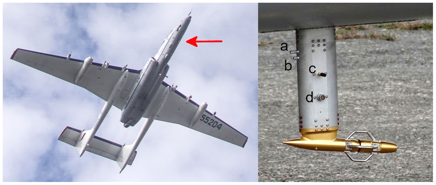
Figure 1Left: the M-55 Geophysica shortly after takeoff from Tribhuvan International Airport in August 2017. The red arrow points to the sampling inlet of the ERICA. Right: the sampling inlet of the ERICA installed on the aircraft, where (a) is the backing-line exhaust port, (b) the inlet bypass exhaust port, (c) the wireless LAN (local area network) antenna, and (d) the communication connector.
Information from the sensors of the aircraft is provided from the unit for connection with scientific equipment (UCSE) to the scientific instrumentation over a dedicated serial communication bus. This data stream contains the GPS time and coordinates, altitude, pressure, temperature, wind velocity and direction, and all relevant flight angles (i.e. the drift, roll, pitch, and slip angles; the true heading; and the angle of attack).
The design and development of the ERICA followed a top-down approach, starting with the analysis of the anticipated conditions in the UTLS. The aerosol concentration and size distribution in this region, together with the wide ambient temperature range from +40 to −90 ∘C, the very low (down to 50 hPa) ambient pressure at high altitude, the high speed (up to 200 m s−1) of the platform, and the absence of an operator on board, require extensive design considerations. Moreover, the technical specifications and limitations of the aircraft were taken into consideration; such parameters are the lack of pressurized instrument compartments, the absence of an instrument operator on board, the electrical supply limitations, and the high speed of the platform. Several aspects of the technical developments for the integration and the successful fully automated operation of the instrument on the aircraft are discussed in the following sections.
4.1 Mechanical adaptation, pressure and temperature control
Despite the very low temperatures in the UTLS, the very low density of gas molecules at high altitudes results in inefficient convective cooling for any operating mechanical or electronic device. Overheating in electronics can induce various problems, from thermal noise-related artefacts to component malfunction that can lead to a complete system failure. Additionally, low ambient pressures can cause mechanical deformation and, ultimately, damage of enclosed electronic components such as electrolytic capacitors. Moreover, the alignment of the aerosol particle beam and that of the optics of the laser systems are very sensitive to thermal stress. The complexity of the instrument, in conjunction with the need for the use of off-the-shelf components, qualified the option of enclosing the entire instrument inside a pressurized container as the most efficient and reliable.
A specialized pressure vessel (PV) was manufactured by the operator of the aircraft. The PV is designed to be installed inside the allocated bay of the aircraft, where it is mounted on four pods at the bottom of the fuselage via an adapter with coiled-wire vibration isolators. The PV resembles an aluminium cylinder and has a length of 1.5 m and an outer diameter of about 0.8 m. Its internal design provides a pair of rails which run along the lower half of its round cross-section and facilitate the insertion and removal of the ERICA by sliding it in and out. Consecutively, a mating frame was built to house the instrument. The equipment is distributed inside the removable frame, while most of the power supply units are mounted to the bottom of the PV so that the heat generated by them is directly conducted to the PV wall. Multiple cables connect the power supply units and other sub-systems of the PV with those inside the frame. The total mass, including the instrument, the PV, and the adapter, is 360 kg, approximately. Photographs of the instrument and the PV can be found in the Supplement.
Two round lids with a diameter of 0.8 m, featuring rubber O-rings, seal the PV at its two edges. Pressurization tests confirmed that the PV can withstand a positive differential pressure (pinternal−pambient) of 1600 hPa exhibiting minor pressure loss over several hours. Before each flight operation, the PV is sealed, filled with nitrogen, and pressurized to 1150 hPa (absolute pressure). The dry nitrogen atmosphere prevents problems associated with water vapour condensation in the electronics and the high-voltage systems of the mass spectrometers while it constitutes a means of fire protection. An additional nitrogen refill system was implemented to compensate for the potential pressure loss anticipated during a flight. This system consists of a 2 L gas cylinder containing pressurized nitrogen at 70 bar and a customized mechanical pressure regulation system which releases additional nitrogen when the pressure inside the PV drops below 850 hPa. The pressure inside the PV and the reserve nitrogen pressure are continuously monitored during the flights. A safety interlock system switches off sensitive sub-systems in the case of extreme depressurization (pinternal<700 hPa).
Inside the PV, multiple fans force the nitrogen into a circular flow in order to distribute the generated heat and equalize the temperature. A large number of sensors (more than 40) monitor the temperature of most system components and that of the circulated nitrogen at several different locations inside the PV. Additional cooling can be provided by a heat exchanger that circulates silicone oil through tubes that are routed outside the PV and into the strut of the aerosol sampling system, which is exposed to the airstream during a flight. This cooling feature is similar to that used in other instruments which have operated on the same aircraft (Weigel et al., 2009). Finally, a custom electrical heating system, with a power of 1600 W, can warm up the circulated nitrogen inside the PV if necessary. All cooling and heating systems are controlled by a dedicated unit described in Sect. 4.4.1.
The enclosure of the entire instrument inside a sealed vessel, with the vessel itself installed in a closed fuselage compartment, necessitates the cooling of the system, especially during ground operation. Laboratory tests performed under the anticipated power consumption conditions showed that a steady-state difference between the PV's inner air and outer room air temperature reaches 20–25 K (at sea level pressure). The fact that this temperature difference would rise even higher with the PV enclosed in Bay II called for powerful ventilation of this compartment. On the ground and at ambient temperatures higher than 10–15 ∘C, an air-conditioning unit is required during the operation of the ERICA. Consequently, a port for a cooling hose was made on the starboard side of the Bay II cowling. A hatch on the port side of the cowling and a gap around the strut of the aerosol inlet (see Sect. 4.2) serve as exhausts for the cooling air. The forced-air cooling by the air-conditioning unit has to be applied for as long as possible during the flight preparations in the hangar or at the apron. To bridge the time period without cooling, i.e. between the disconnection of the air-conditioning unit (“hands-off”) and takeoff, the instrument is kept in a power-saving non-sampling mode (Sect. 4.5). Due to the high thermal capacity of this 360 kg heavy instrument (mostly consisting of aluminium), periods of about 45–60 min between the disconnection of the air-conditioning unit and takeoff are manageable, as this may result in a maximum temperature increase of about 10 K inside the PV, which is swiftly compensated for by the fast ascent of the aircraft into colder air. For flights at the maximum cruise altitude of about 20 km where very low ambient pressures (down to 55 hPa) are experienced, heat dissipation only by radiative cooling has been calculated as a worst-case estimate. The area of the PV's wall at a temperature of 20–25 ∘C can radiate all the generated heat of the instrument, provided that the temperature of the adjacent cowling wall is sufficiently cold (−50 ∘C or colder). The latter condition was expected for most flight profiles of the M-55 Geophysica. Moreover, additional cooling is provided by cold air flowing inside Bay II through a gap around the aerosol inlet strut. Overall, the cooling power proved to be sufficient during all accomplished flights, as discussed in Sect. 5.2.
4.2 Aerosol sampling system
There are no permanently installed measurement air inlets on the M-55 Geophysica aircraft, and thus, the design and development of a new aerosol inlet were necessary for the integration of the ERICA. To sample outside the boundary layer of the aircraft and to minimize the protrusion of the sampling inlet from the fuselage, a position close to the nose of the aircraft was selected. The inlet strut positions the point of air sampling at about 30 cm away from the fuselage and thus well outside the aircraft boundary layer, which can be estimated with about 6 cm at the inlet mounting position (Krämer et al., 2013). For simplicity, the inlet system was kept together with the instrument and installed at Bay II (see Fig. 2). To keep the sampling line short and minimize particle losses in the sampling line, the mass spectrometer was placed inside the PV with its inlet side facing forward. A downward orientation of the inlet strut had several advantages as compared to a sideward horizontal or any other orientation. First, sampling of undisturbed air is possible during sideslip of the aircraft. Second, positioning an inlet on the side of the fuselage would require much stricter structural considerations as, in this case, it would be in front of the engine intake. Last, the adopted vertical inlet orientation simplified the mounting procedure of the Bay II cowling and its modification.

Figure 2Top: drawing of the aircraft with the ERICA installed. Bottom left: a close-up of the pressure vessel showing the inlet sampling and bypass lines. Bottom right: a cross-section of the ERICA inlet head. All dimensions are in millimetres.
To limit cowling modifications, the inlet was mechanically mounted on the PV rather than the cowling or the fuselage. For this solution, a central and relatively small rectangular opening in the single-piece cowling was manufactured in such a way that the complete cowling could be mounted from below, after the installation of the instrument in Bay II. Additionally, two small plates were fabricated to minimize the surface of the opening around the inlet strut, allowing a narrow gap of about 2–3 cm, which allows for the movement of the PV (suspended by coiled-wire vibration isolators). This gap permitted ambient airflow into Bay II during flight according to the heat management considerations described in Sect. 4.1. In this configuration, the aerosol inlet head (see Fig. 2) is designed for simple and quick installation, which takes place during the pre-flight procedure. This practice minimizes the risk of damage caused during cowling installation and removal or by tow bar handling while the aircraft is towed from the hangar to the apron. Moreover, the inlet strut itself does not protrude into the space, in which it may interfere with the tow bar; this is indicated in Fig. 2 with a straight line from the front wheel to the sideslip sensor located at the nose dome.
The angle of attack of the inlet head with respect to the strut was chosen taking the most probable angle of attack of the aircraft during flight into account, with a focus on stratospheric sampling. Based on the analysis of the aircraft data from research flights of M-55 Geophysica, a value of 7∘ has been selected as a representative average from a range of possible angles between 4 and 10∘. The remaining misalignment of the ambient airflow with respect to the inlet's centre line is further reduced with a so-called shroud, an aerodynamically shaped tube mounted upstream of the inlet, which aligns the airflow with the centre line of the downstream inlet (see Fig. 2).
Downstream of the shroud, the airstream is decelerated by two diffusers. Before the sampled air enters the sampling line, its speed reduction substantially reduces particle losses and self-contamination. Moreover, while the material used for the fabrication of the aerosol inlet strut and head is aluminium (EN AW 7075) and the sampling tubes are made of stainless steel (1.4404), the shroud and both diffusers are made of gold-plated aluminium. This technique has been used in order to detect possible self-contamination issues, which are discussed in Sect. 5.3. Only the inner walls of the sampling line can be considered a source of contamination; however, such probability is greatly reduced thanks to the much lower flow speed (<5 m s−1) at that point. The results demonstrating the effectiveness of this gold coating are presented in Sect. 5.3.
The design of the inlet head shape is very similar to that of the inlet of the CARIBIC (Civil Aircraft for the Regular Investigation of the atmosphere Based on an Instrumented Container) II project (Brenninkmeijer et al., 2007). The outer diffuser (4.0 mm intake to 18.6 mm diameter, Fig. 2) decelerates the air, nominally by a factor of 21.6. An inner diffuser, which is incorporated in the inlet tube (4.57 mm inner diameter), further reduces the air speed by a factor of about 1.8. Consequently, the speed of the airstream reaching the first bend of the sampling tube is reduced by a factor of about 39. The typical true air speed range of 165–200 m s−1 corresponds to approximately 4.5 L min−1 of isokinetic sample flow. Moreover, laminar flow conditions inside the sampling line are valid under all flight conditions. The results of computational fluid dynamics (CFD) calculations are presented in the Supplement. The dynamic pressure range of 12–15 hPa can be seen as the difference between ambient (static) and inlet pressures during a flight, as shown in the top-right part of Fig. 7.
For the configuration described above, the sampling tube comprises four bends (). The total length of the sampling line between the inner diffuser (3.4 mm aperture, Fig. 2) and the aerodynamic lens measures 0.9 m. Therein, downstream of the first part of 0.66 m in length, the flow is split to allow for an additional flow path, which is controlled by a diaphragm (bypass) pump, as shown in the bottom-left part of Fig. 2. In addition to the instrument's maximum sampling flow of about 1 L min−1 (ambient), the speed of the pump was set to a constant volumetric flow rate of 3.5 L min−1. This additional flow rate is set so that it creates a total inlet flow of 4.5 L min−1 with the aim to achieve nearly isokinetic sampling at low ambient pressure and high aircraft speed, as expected in the altitude range of interest. Such near-isokinetic conditions reduce the uncertainties associated with possible particle-size-dependent enhancements. At lower flight altitudes and, consequently, lower aircraft speeds, the inlet samples slightly super-isokinetically. The relatively short sampling line of the ERICA on the M-55 Geophysica translates into low diffusional particle losses and low sampling tube residence times: on average, a value below 0.3 s is estimated.
The overall sampling efficiency of the ERICA sampling system is given by the product of the aspiration efficiency of the aircraft inlet, the transmission efficiency through the inlet, and the transport efficiency through the sampling line. Considering the layout of the ERICA inlet, based on CFD modelling, and the application of a shroud, the aspiration efficiency for the majority of particles of interest here, i.e. the accumulation-mode particles, can be assumed to be 1. The similarity to the CARIBIC inlet allows us to estimate the inlet transmission efficiency to be higher than 95 % for the same particle size range. The losses for coarse-mode particles are definitely higher but are hard to quantify without laborious wind-tunnel experiments. The parameters of the sampling tube listed above (flow, length, diameter, bends, pressure, temperature) were used to estimate the sampling line transport efficiency during airborne sampling for three representative values of air pressure. The lowest ambient pressure experienced during a stratospheric flight with the M-55 can be as low as 54 hPa, as shown in Fig. 7. However, due to the forward-facing orientation of the inlet, which effectively exposes it to a higher dynamic pressure, a value of 65 hPa is considered the lowest-case condition for particle loss calculations. Indeed, a pressure sensor connected to the inlet tube recorded a minimum value of 68 hPa during one of the research flights wherein the aircraft reached 20 km altitude. Calculations were performed with the software tool “Particle Loss Calculator” (von der Weiden et al., 2009), and the results are plotted versus the relevant particle size range of the ERICA, as shown in Fig. 3. At the lower end, where a size of 60 nm is considered the sensitivity limit of the ERICA-AMS, the tube transport losses are below 5 %. At the upper end of about 2–3 µm, where the transmission of those larger particles is mainly affected by the aerodynamic lens, the worst-case (at 65 hPa) tube losses are in the range of 10 %–20 %. Associated with the deceleration in the two diffusers in the inlet is a ram heating of about 15 K. Calculations performed for the quite similar CARIBIC inlet system showed that most of the particulate water evaporates during the heating in the inlet system (including the sampling lines) but the majority of sulfuric acid for accumulation-mode particles remains on the particles (Hermann et al., 2016). Hence, results obtained by measurements downstream the ERICA inlet can be considered representative of dry ambient particles.
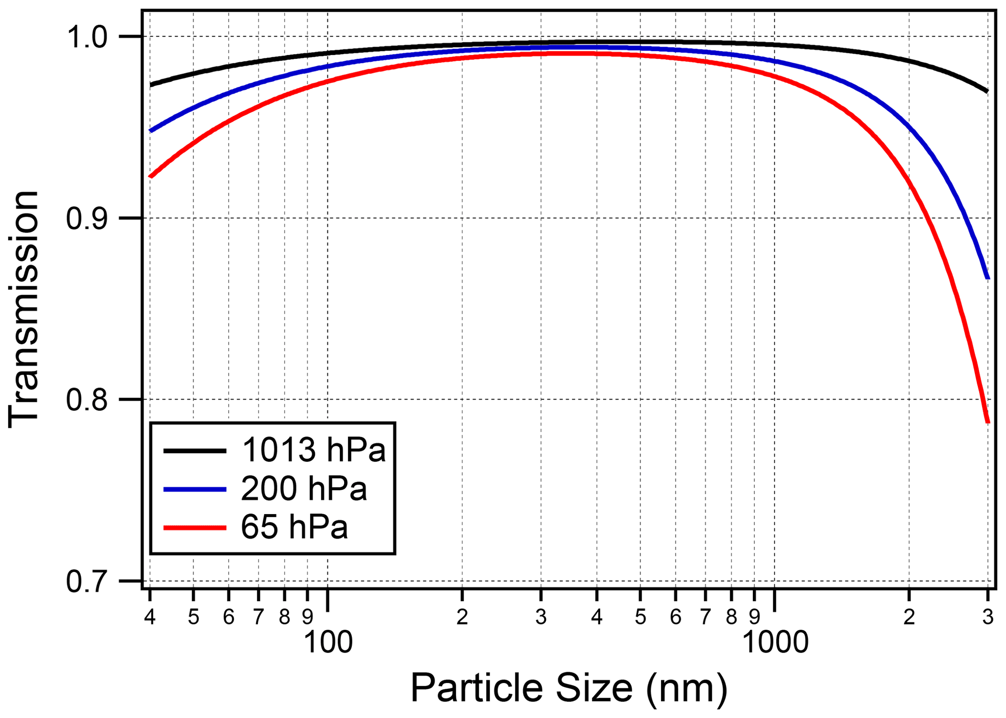
Figure 3Calculated particle transmission of the aerosol sampling line versus aerosol particle diameter, at three different pressures inside the line.
The final stage of the aerosol sampling system comprises an aerodynamic lens. Two aerodynamic lenses were tested during instrument development (Hünig et al., 2022). In the final design, the “intermediate pressure lens” (IPL; Peck et al., 2016) acquired from Aerodyne was used. For the aerodynamic lens to operate at its optimal pressure, a module called the constant-pressure inlet (CPI) was developed and installed upstream of the lens. The principle of operation of this system and its particle transmission performance with the ERICA are described by Molleker et al. (2020). Various mechanical parameters of the CPI system were optimized to improve particle transmission over the wide ambient pressure range encountered during the flights (54–1000 hPa).
Moreover, since the aerosol inlet is the only external part of the ERICA, it has been utilized for a number of auxiliary functions, which are indicated in Fig. 1: (a) and (b) exhaust tubes for the inlet bypass (additional flow) line, as well as for the backing vacuum pump on the rear side of the inlet strut; (c) a wireless LAN antenna for remote controlling the instrument during the hands-off phase of pre-flight operations at the apron; and (d) an electrical connector incorporating LAN and USB (universal serial bus) connectivity for remote control and data transfer.
Last, to prevent icing on parts which might affect sampling quality, four cartridge heaters, with a combined power of 120 W, were installed into the shroud and the main head/diffuser. Two resistance temperature detectors (RTDs) inside the inlet head were used to receive temperature feedback for the thermostatic control of the RTDs.
4.3 Electrical power distribution
The generators of the aircraft provide aviation-standard three-phase electrical power at 115 VAC, 400 Hz. A secondary distribution circuit supplies several instruments directly with 28 VDC. The ERICA is powered by two of the three AC phases, via two lines rated at 15 A each and from one 28 VDC line rated at 25 A. The AC and DC power lines are fed into the instrument through two separate vacuum-tight bulkhead connectors on the walls of the pressure vessel.
The current supply limitations of each power line and the power requirements of the multiple sub-systems of the instrument called for the design and development of a complex electric power conversion and distribution system. Low-pass filters are used on all three input power lines to cut off potential radio frequency (RF) noise present on the power lines and protect the systems of the ERICA.
On the first AC line, a 1000 V A (FCSS1000, RIPEnergy AG) frequency converter is employed for the supply of the two largest 230 VAC, 50 Hz consumers: (a) the Nd:YAG laser unit and (b) the high-voltage power supply of the bipolar ToF spectrometer. Additionally, two AC-to-DC converters comprising five separate DC power supply modules (VIPAC series, Vicor Corporation), with a combined output power of 1050 W, provide three 24 VDC and two 12 VDC output lines. These lines supply all vacuum pumps, the data acquisition units, and most of the peripheral control units. The second AC line is used exclusively for the supply of the heating system, which requires 1600 W at 115 VAC.
The 28 VDC line is used to supply the main computer and all critical sub-systems of the instrument. The line is backed by an uninterruptible power supply (UPS) unit (DCU20, nextys), which is supplemented by two sealed 12 V lead-acid batteries connected in series (24 V). The capacity of the batteries is 12 A h, which guarantees more than 1 h of continuous operation for all critical sub-systems. Additionally, due to the limited power ratings of the AC lines, an inverter is used for the conversion of 28 VDC to 230 VAC, 50 Hz, which supplies the high-voltage power supply unit of the C-ToF-AMS.
For maintenance-free and reliable autonomous operation, any wire fuses and thermal circuit breakers were eliminated from the power distribution system design. All power lines are protected by polymeric positive temperature coefficient (PPTC) resettable fuses, exclusively. In addition, important units are powered through relay switches that can be remotely controlled from the software for saving power or power cycling those units; the use of this feature under real flight conditions is discussed in Sect. 5.2.
The total power consumption of the instrument can exceed 1500 W at power-up. During normal operation without heating, the power consumption is 1200 W on average. When the instrument does not sample air, the power consumption can be reduced by 50 % to save energy and prevent overheating during the pre-flight operations.
4.4 Electronic hardware
The requirements for the electronics of the instrument led to a modular system design approach. The electronic hardware of the ERICA constitutes a diverse combination of commercial components, customized outsourced units, and microcontroller-based embedded systems, which were designed by our team and developed in our workshops. The system consists of a main computer and 16 sub-systems with specialized functionality which cover the needs for power control, vacuum system operation, temperature control, task sequencing and automation, error detection and fail-safe operation, precise timing and triggering of laser pulses, and data acquisition and logging, as well as telemetry and remote control over a satellite communication link.
All data logging is carried out by the main computer, which is a high-performance system built around a quad-core processor (i7-4790K, Intel), with 16 GB RAM and a 512 GB solid-state drive, running a Microsoft Windows 7 64-bit operating system. The computer communicates either directly or indirectly with all sub-systems over separate data connections of different protocols (Ethernet, USB, RS-232/RS-422/RS-485 and I2C). An overview of the electronic hardware structure is shown in Fig. 4. The sub-systems can be classified into three categories with respect to their functionality, which is discussed in the following sections.
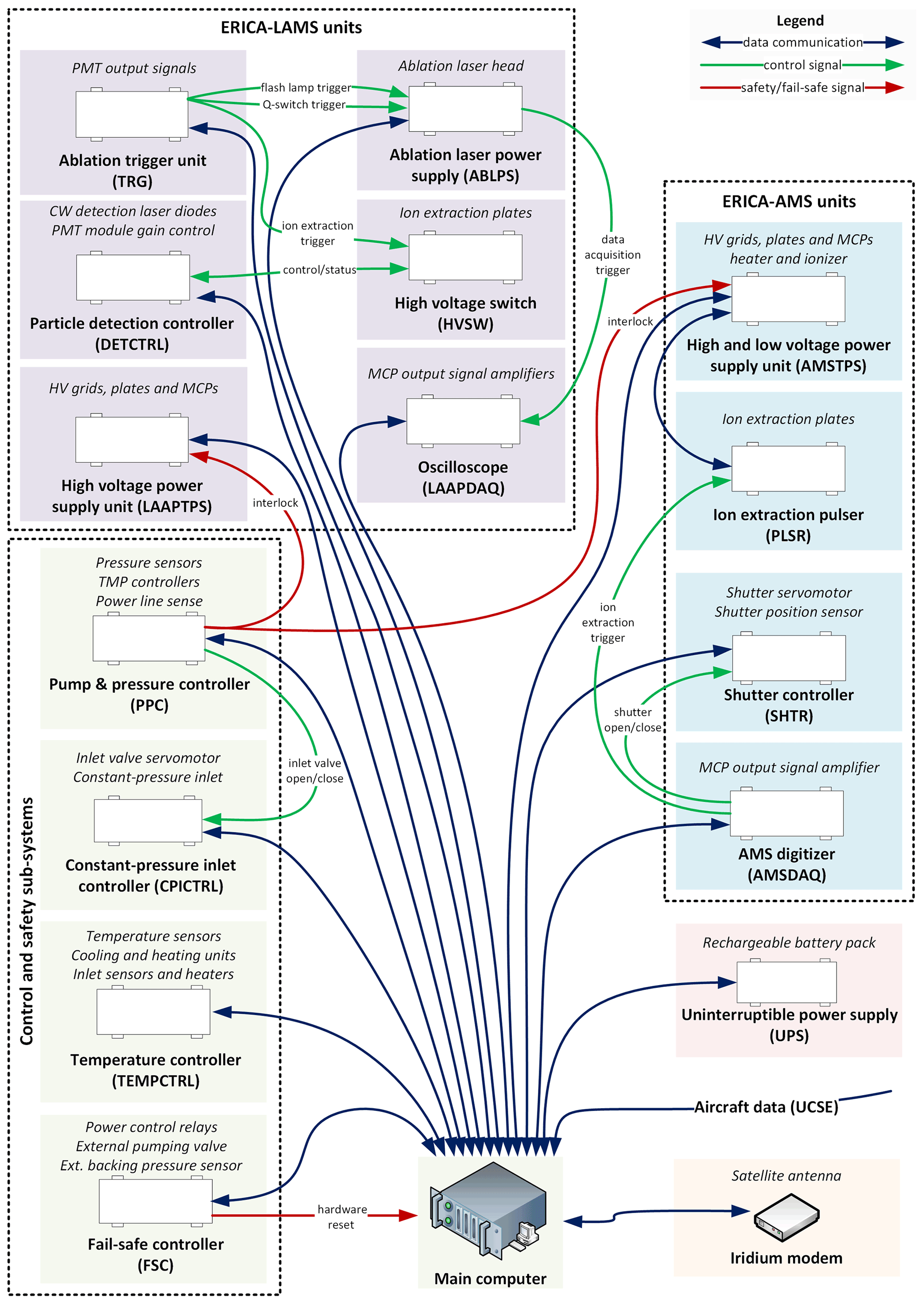
Figure 4Overview of the major electronic sub-systems of the ERICA. Text in italic names additional units connected to each sub-system.
4.4.1 Control and safety sub-systems
Critical operations, such as vacuum control and emergency interlocking, are performed by specialized stand-alone embedded systems that are backed by a UPS unit. Redundancy has been used in some of these sub-systems by duplicating important sensors and signal lines and employing error detection logic, while all of them include watchdog timers that guarantee an automatic restart in the case of software failure. These units are described in this section.
The pump and pressure controller (PPC) is a unit which controls the operation of the vacuum system. It can interface up to 13 analogue pressure sensors of various types, start and stop the three TMPs, and control the speed of the two backing pumps. It provides an interlock feature for switching off the high-voltage power supplies in the event of high pressure inside the vacuum chambers or low pressure inside the pressure vessel of the instrument due to excessive pressure loss during a flight. Additional features include the activation of the ERICA after a pre-set delay (takeoff countdown timer) or when a particular altitude is exceeded, the control of the opening and closing of the main inlet valve and the detection of source power disruptions. The PPC plays a key role in the automation of the instrument, which is described in Sect. 4.5.
The constant-pressure inlet controller (CPICTRL) employs a PID (proportional–integral–derivative) control system for the regulation of the sampled air pressure in front the aerodynamic lens. The operation of this system has been described by Molleker et al. (2020). Additionally, this unit drives the servomotor that opens and closes the main inlet valve when the respective commands from the PPC unit are received.
The temperature controller (TEMPCTRL) comprises the drive and readout electronics for the RTD sensors of the inlet and controls its de-icing heating elements, as discussed in Sect. 4.2. This unit also controls a network of up to 64 temperature-sensing modules, which are distributed in a three-dimensional virtual grid covering the entire PV and specific components of the instrument. The readings of selected sensors are continuously checked against programmable set points so that parts of the cooling and heating systems can be activated or deactivated.
The fail-safe controller (FSC) unit operates as a watchdog timer for the main computer; it can induce a hardware reboot in case the software running on the computer stops responding. Additionally, power relays controlled by the FSC are used for deactivating several units when the system operates in an energy-saving mode, which is described in Sect. 4.5.
4.4.2 Single-particle mass spectrometer electronics
The operation of the ERICA-LAMS is based upon six sub-systems that serve for the detection of single particles and the triggering of the ablation/ionization, the generation and control of the electrostatic fields that exert forces on the ions, and the data acquisition. These units are presented in this section.
The detection controller (DETCTRL) and ablation trigger unit (TRG) units are two complementary sub-systems designed for the operation of the optical detection of sampled particles. The former unit includes two separate programmable current sources which drive the CW laser diodes and two voltage sources that control the gain of the PMT modules. The latter unit samples the PMT output signals, calculates the time-of-flight of each detected particle, and triggers the ablation laser unit with a 40 ns precise timing.
The ablation laser power supply (ABLPS) is a part of the Quantel Ultra 50 system. The unit provides power to the ablation laser head and carries out its control, temperature monitoring, and cooling. The cooling action is performed by the circulation of coolant, which is typically distilled water mixed with ethylene glycol, through flexible tubes that connect the laser head with a heat exchanger, which is located inside the ABLPS unit. For precise timing of the particle ablation, the unit has two separate inputs for triggering the flash lamp and the Q-switch of the Nd:YAG laser. The Q-switch trigger output is connected to the ERICA-LAMS data acquisition trigger input so that the onset of data acquisition occurs exactly when the laser head shoots.
The ERICA-LAMS ion spectral data acquisition (LAAPDAQ) unit is a compact computer-based oscilloscope (Picoscope 6404C, Pico Technology) with four channels, 8-bit vertical resolution, and a total sampling performance of 5 GS s−1 (gigasamples per second). The current signals of the two MCP detectors (one for anions and one for cations) are first conditioned and then split and simultaneously sampled by two separate oscilloscope channels each (four channels in total). The channels have different input voltage ranges, a small scale, and an overlapping large scale for each polarity to effectively broaden the dynamic range of the ion detection. The shortest attainable temporal sample separation in this mode of operation is 0.8 ns. The acquisition trigger signal is provided by the trigger output of the ablation laser Q-switch. The raw spectral information for each ablated particle is temporarily stored in the buffer memory of the unit and then is streamed to the main computer over a USB 3.0 connection. More than 25 particles per second can be sampled with no need for data compression. This performance does not constitute a bottleneck for the overall sampling throughput, which is ultimately determined by the maximum shooting rate of the Nd:YAG laser unit, which is typically set to 10 Hz.
The ERICA-LAMS high-voltage power supply (LAAPTPS) is a commercial unit manufactured by Tofwerk AG. The unit provides multiple adjustable voltage outputs for the generation of the electrostatic fields that are required for the operation of the bipolar ToF-MS.
The high-voltage switch unit (HVSW) is built around two solid-state high-voltage MOSFET (metal-oxide semiconductor field-effect transistor) switches (HTS 61-03-C, Behlke), which are triggered by the TRG unit up to a few microseconds after each laser shot. When not triggered, these switches tie the extraction plates to ground. This technique, which has been previously reported and is referred to as delayed ion extraction (Brown and Lennon, 1995), practically eliminates the effective ion extraction forces that can deflect aerosol particles, which bear a charge, as they fly by the ion extraction region. Measurements with the ERICA-AMS have confirmed that a permanently applied field results in high particle losses, while the introduction of this unit substantially increases the particle mass detection efficiency (Hünig et al., 2022).
4.4.3 Continuous-ionization mass spectrometer electronics
The ERICA-AMS is based upon the C-ToF-MS design. Its high- and low-voltage supply unit (AMSTPS) is manufactured by Tofwerk AG. The AMSTPS unit generates the high voltages needed for the operation of the mass spectrometer, as well as low voltages that supply the vaporizer and ionizer components.
As with the operation of other instruments employing the C-ToF-MS, such as the Aerodyne ToF-AMS, while ion generation is continuous, the ion extraction is performed in bunches. The extraction is achieved by an additional unit, which is referred to as the pulser (PLSR). This unit energizes the extraction plates when it receives a trigger signal from the data acquisition unit, which is described below.
For the operation of the shutter, a dedicated control unit was developed. The shutter controller (SHTR) drives the servomotor of the shutter and monitors the position of its shaft by reading out a resistive position sensor. The movement of the shutter is controlled by a signal, which is sent by the data acquisition unit.
The data acquisition unit (AMSDAQ) is a commercial single-channel digitizer (ADQ1600, SP Devices). This device is capable of sampling at 1.6 GS s−1 with a high vertical resolution of 14 bits and features real-time waveform averaging at the hardware level. Additionally, the unit coordinates the measurement process by generating trigger pulses for the operation of the ion extraction pulser and by controlling the position of the shutter via a custom interface. The averaged spectra are streamed to the main computer over a USB 3.0 connection.
4.5 Operation, software development, and automation
The procedures for each scientific flight can be grouped into three phases. The first phase serves for the calibration and preparation of the instruments, which can be either installed or detached from the aircraft; this phase typically begins hours or even days before each takeoff. The second phase comprises the pre-flight operations, including the final tuning of the instruments, which typically take place at the airport apron during the last hours before takeoff. The last phase is the actual operation of the instrument during the aircraft taxiing, takeoff, flight, and landing. During the first and second phases, full software access to the instrument is possible with the use of remote-control techniques, which are described in Sect. 4.6. During the third phase, the instrument operation is completely stand-alone and fully relies on automation.
One of the peculiarities in the operation of scientific instrumentation on the M-55 Geophysica aircraft is the interruptible nature of the power supply. More specifically, it is a common practice to power some instruments directly from the mains during the pre-flight operations in the hangar before connecting them to the electrical power distribution system of the aircraft. Then, at the apron, the aircraft is initially supplied by a ground power unit (GPU) and, with the completion of the pre-flight operations, its electrical power distribution system is switched over to the on-board generators. During this power transfer, voltage dips are common and usually long enough (up to 1 s) to interrupt the normal operation of an instrument. Due to these conditions, it is necessary to protect and back up the critical sub-systems with a UPS unit (described in Sect. 4.3), and the detection of power outages and the automatic restart of the affected units must be provided for the reliable operation of the instrument.
Additional considerations have to be made for the safe operation of a mass spectrometer with respect to the pressure inside its vacuum system. The sensitivity of particular components, such as the TMPs and MCP detectors, necessitates the provision of safety interlocks and the design of appropriate task sequencing when the system starts up. A simplified description of the sequence of the tasks performed by the pressure control system of the ERICA is given in the left section of Fig. 5.
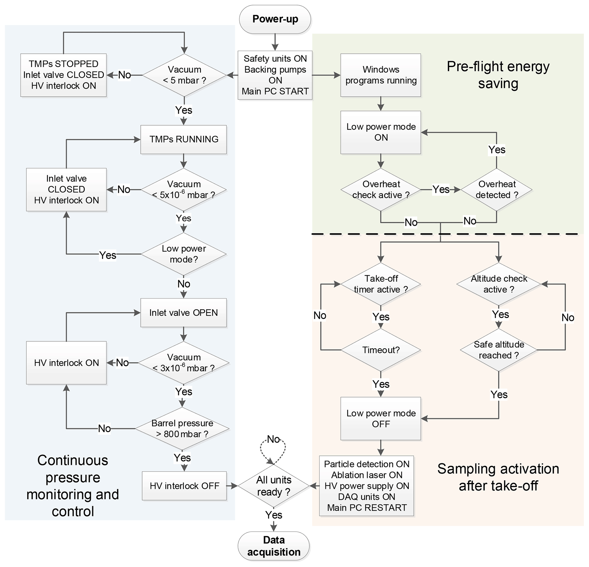
Figure 5Flow chart of the automation of the main tasks performed by the ERICA during start-up.
Moreover, the temperature control of the instrument is of vital importance. Many critical components of the instrument, such as the TMPs, must be kept within narrow operating temperature ranges. It is worth noting that the most strenuous heat stress is typically induced after the transition from the second flight operation phase to the third; this is when pre-flight preparations at the airport apron are completed and a hands-off command is given. At that stage, the air-conditioning units are disconnected from the aircraft while the instruments are running. On several occasions, the takeoff must be delayed and the pilot is asked to wait for an extended period of time while the aircraft is standing at the apron, the taxiway, or the runway.
To prevent the overheating of the instrument under those circumstances, a low-power mode (LPM) of operation was introduced and activated during the pre-flight operations. When operating in the LPM, the inlet valve of the instrument is closed and unnecessary units are switched off; these actions result in a total power consumption reduction of approximately 50 % compared to that during normal operation. The LPM is typically selected during the pre-flight operations, when no measurements need to be performed and while forced-air cooling by the air-conditioning unit is applied. The instrument automatically restarts and returns to the normal mode of operation when either a countdown timer reaches zero or a predefined altitude has been reached.
In addition, an optional overheating detection feature checks whether several units are below their maximum operating temperature, as defined by their specifications. This feature can automatically switch the instrument to LPM if any of the monitored units is overheated. However, considering that this option would stop the measurements, it is only used on the ground. Instead, during a flight, the detection of overheating only generates a warning indication which is relayed to the ground station, as discussed in Sect. 5.6; the measurements continue unabated unless the thermal protection system of an individual unit (for example, the main computer) switches it off. This risk was assessed and deliberately taken considering the importance of carrying out the measurements even while exposing the equipment to thermal stress. However, the temperature control performance of the ERICA prevented any overheating under real flight conditions, as discussed in Sect. 4.2.
A simplified overview of the automated tasks performed before and during flight is given in the right section of Fig. 5. The time delay and altitude set points are selected so that the instrument starts taking measurements during or shortly after takeoff. If necessary, especially in the case of a delayed takeoff, the instrument can remotely be commanded to remain in the LPM for longer time. In practice, this remote-control feature was exploited in most of the flights from the airport in Kathmandu in 2017 due to prolonged waiting times (up to 1 h) before takeoff, in conjunction with high ambient temperatures (up to 35 ∘C).
When the system returns to the normal mode of operation, all units are powered up and the main computer restarts. The computer software was developed using National Instruments LabVIEW language. Following a specific sequence, a series of computer programs are executed at start-up. Each of them communicates with its respective hardware sub-system and ensures that the associated units are correctly initialized. These programs also serve for the system parametrization and monitoring, as well as for the data acquisition, logging, and plotting. Additionally, a commercially available program (TofDAQRec), developed and optimized for the needs of the ERICA by Tofwerk AG, performs the ion spectral data acquisition of the ERICA-AMS.
Critical tasks, such as the vacuum control, the temperature control, power outage detection, and main computer failure detection, are performed by dedicated units. The basic operation of these units is stand-alone, and thus, it does not rely on software running on the main computer. Their hardware is built around microcontrollers, which are programmed with bespoke firmware written in the C language. Information that is crucial for the operation of these units, such as pressure and temperature set points, is stored in their on-board electrically erasable programmable read-only memory (EEPROM).
4.6 Telemetry and remote control
Apart from the automated and operatorless design of the ERICA, the option to monitor and control the instrument not only during the flights but also during pre-flight operations constituted one important design consideration. As a result, remote-control interfaces that serve this purpose were developed.
For the control and calibration of the instrument on the ground, an externally accessible communication connector was added to the inlet strut, shown in Fig. 1. This connector features galvanically isolated Ethernet and USB connections to the main computer, which enable the remote control of the instrument using commercial software, as well as the direct connection of calibration equipment, such as an external condensation particle counter (CPC). The communication connector is also used for downloading the measurement data after each flight with no need to remove the instrument from the aircraft.
Additionally, a compact 2.4 GHz antenna is installed on the inlet strut (see Fig. 1). The antenna is internally wired to an optically isolated wireless LAN adapter communicating with the main computer. When coupled with a directional antenna at the control side, the range of the wireless data link can reach 100 m. This feature enables the remote monitoring and control of the instrument at the apron position, typically during the pre-flight operations, providing full access even after hands-off and until the beginning of taxiing.
For the in-flight communication, an iridium short-burst data (SBD) satellite modem and antenna were installed in a compartment on the top of the aircraft, aft of the cockpit. To maintain its operating temperature within limits, the modem unit is heated by a resistor when the ambient temperature drops below 5 ∘C. The power supply of the modem unit and its communication with the instrument are achieved through a cable harness that is routed through the fuselage. Differential signalling is used for noise immunity due to the 20 m long wiring between the ERICA and the modem.
The SBD protocol provides bidirectional communication between the instrument and the ground control station. Binary information messages are composed by the communication software running on the main computer of the instrument, and they are transmitted at regular intervals of 1 to 3 min. Each message has a fixed length of 256 B and comprises all important housekeeping information, including all pressure and temperature sensor readings, counter values, and status bits for all sub-systems. All information is encoded for reduced data usage. More than 300 individual system parameters are continuously checked; if any is found to be outside its nominal limits, a respective fault or warning is logged and propagated to the ground station. All faults and warnings are grouped in order to facilitate the location of a problem and troubleshooting if needed.
The transmitted messages are downloaded by software running on the ground control station and are concatenated to form a single array of data. A graphical user interface (GUI) decodes the binary information and depicts the current system condition. Plots of several system parameters versus time, a flight chart, and troubleshooting reports can also be shown. A screenshot of the remote monitoring GUI is shown in the Supplement.
The optional remote control of the ERICA can be performed by means of encoded commands that are generated by software running of the ground control station. The remote command set covers all the meaningful operations that can be performed during a flight, such as overriding automated procedures, turning auxiliary units on and off, power-cycling malfunctioning sub-systems, restarting programs, or rebooting the main computer. These commands are sent from the ground control station as binary messages. These messages are relayed by the iridium constellation to the modem of the instrument. During each flight, the modem establishes a communication session with the satellite network and checks for new command messages every 1 min. If a new command message has been sent from the ground, it is downloaded to the main computer, wherein a program decodes it and executes the respective commands.
5.1 Field deployments
The ERICA was first deployed in a field campaign which took place at the air base of Kalamata (KLX), Greece, in August and September 2016. This mission constituted the first phase of StratoClim (Formenti et al., 2015), a collaborative research project funded by the European Commission. These flights served for testing newly developed scientific instruments, including the ERICA, under real conditions while performing atmospheric measurements in the eastern Mediterranean region and providing an opportunity to sample air masses from the outflow of the decaying Asian monsoon anticyclone (AMA). The ERICA operated continuously from the first takeoff of the M-55 Geophysica and during all three scientific flights (KLX 1–3), clocking up more than 12 flight hours. The instrument recorded important information about the chemical composition of aerosol particles found at true (barometric) altitudes up to 19.8 km with single-particle mass spectra containing both ion polarities by the ERICA-LAMS and concurrent measurements of particulate sulfate, nitrate, ammonia, chloride, and organics by the ERICA-AMS.
The second deployment of the instrument took place at the Tribhuvan International Airport of Kathmandu (KTM), Nepal, in July and August 2017. The ERICA was part of the scientific payload on all eight scientific flights (KTM 1–8). The flight paths spanned the geographical area with latitudes from 21 to 27∘ N and longitudes from 79 to 90∘ E. This field campaign constituted the main phase of the StratoClim aircraft operations and aimed at the direct study of the ATAL. The flight patterns included long stretches in the tropopause region and the lower stratosphere above Nepal, India, Bangladesh, and the Bay of Bengal, as well as portions with rapid ascends, steep dives, and steps of gradually increasing altitude, which serve for the extraction of vertical profiles. A table summarizing the flight data (flight duration, maximum altitude, minimum temperature, and ambient pressure) and maps with the flight paths of all 11 flights are provided in the Supplement.
Regarding the calibration procedures, the optical components of the ERICA-LAMS were aligned, adjusted, and characterized before and after each field campaign. The ERICA-AMS was calibrated every two to three flights by performing a single-ion-signal measurement and a total ionization efficiency calibration. Moreover, thanks to the telemetry system of the instrument, described in Sect. 4.6, continuous monitoring of all critical parameters of the system was carried out by ground operators during each flight, regardless of its autonomous operation.
5.2 Overall system performance and environmental endurance
The overall operation of the ERICA during StratoClim was successful as the instrument performed continuous measurements during all 11 flights. By the end of StratoClim flight missions, the ERICA had logged more than 49 flight hours of continuous measurements, operating at altitudes above 20 km and low ambient temperatures (down to −85.8 ∘C) and pressures (as low as 54.5 hPa). For most of the duration of these flights, the aircraft flew at altitudes above 16 km in order to investigate the UTLS. Figure 6 shows the total time spent in each altitude bin (range).
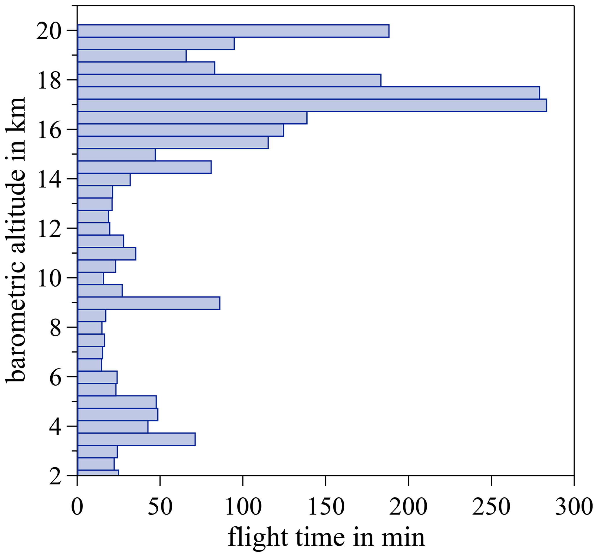
Figure 6Total sampling time of the ERICA in different bins of altitude during all StratoClim research flights in Kalamata, Greece, in 2016 and Kathmandu, Nepal, in 2017.
The environmental endurance of the instrument is demonstrated in Fig. 7, wherein the temperature and pressure profiles during all the operations for the KTM 4 flight, from Kathmandu on 2 August 2017, are shown. The massive increase in internal pressure (pinternal) to 1170 hPa, as illustrated by the solid red line, at approximately 05:45 (UTC), indicates the pressurization of the PV with dry nitrogen during the flight preparations in the hangar. The drop in pinternal during that flight was relatively small (Δpinternal<100 hPa) and partly due to the decrease in internal temperature (Tinternal; dark yellow line) of the PV. Thanks to this small drop in pinternal, the automatic nitrogen refill system (engaging at 850 hPa) was not activated; this was also the case for all flights performed in Nepal (KTM 1–8). The small increase in pinternal during the last minutes of the flight is attributed to a respective increase in Tinternal. The deactivation of the low-power mode (LPM) occurred at 08:15 (UTC). The onset of normal (sampling) operation was followed by an increase in all internal temperatures (brown, dark yellow, and dashed blue lines) by a maximum of 8 ∘C, which was succeeded by a gradual drop due to the exposure of the instrument to constantly low ambient temperatures. However, the temperature of the mass spectrometer block (brown line) was kept within a narrow range from 27 to 42 ∘C, while the ambient air temperature ranged from −82 to 34 ∘C. Most importantly, the harmonic generator (HG) crystal temperature (green line) stayed at a constant temperature of approximately 54 ∘C throughout the flight, ensuring stable and reliable operation of the ablation laser. Last, the performance of the inlet de-icing system is demonstrated by the difference between the temperature of ambient air and that of the inlet head (black and dashed red lines, respectively) during the flight.
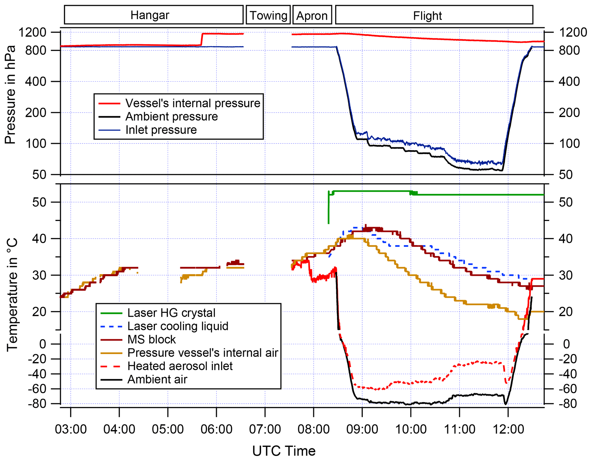
Figure 7Temperature and pressure information during KTM 4 flight operations in Nepal on 2 August 2017. The graph includes the flight preparation time in the hangar and at the apron. The ambient pressure information is provided by the aircraft sensors via the UCSE; all other data are sourced from the sensors of the ERICA. The gaps in the lines indicate times during which the respective units were powered down.
In all flights, the ERICA operated autonomously and according to its design specifications. Its telemetry systems worked continuously and provided real-time information to the ground station, where the instrument operators monitored all important parameters and assessed its performance. On a few occasions, some parameters were remotely tuned during the flight. Most importantly, on three occasions, remote actions had to be taken in order to recover specific sub-systems of the instrument. The first manual intervention occurred during the KLX 3 flight, from Kalamata on 6 September 2016. During this flight, one of the two temperature sensors of the heated inlet failed. This issue triggered a fail-safe function, which provides the deactivation of the de-icing heaters of the inlet due to the lack of a temperature measurement feedback. Even while icing conditions were unlikely in the region of operation, it was decided that the heaters must be turned on during the flight, and thus, they were manually activated from the ground. To protect the heating cartridges and the inlet shroud from overheating, the de-icing heaters were remotely switched off a few minutes before landing. The second incident occurred during the KTM 5 flight, from Kathmandu on 4 August 2017, when the data-acquisition hardware of the ERICA-LAMS stopped responding about 1 h into the flight. A main computer restart was commanded from the ground station, which immediately resolved the problem. Unavoidably, the restart of the main computer also caused a short disruption to the measurements of the ERICA-AMS. This unprecedented glitch led to further development of the remote-control capabilities immediately after that flight. A new feature was added to provide greater flexibility as it allowed for the termination and re-execution of individual Windows applications running on the main computer of the ERICA with no need to restart the entire system. The importance of this upgrade was proven during the KLX 7 flight, on 8 August 2017, when the ERICA-LAMS exhibited the same issue. By restarting the data acquisition software of the ERICA-LAMS only, the single-particle measurements resumed after a few minutes, whereas the ERICA-AMS measurements were totally unaffected.
5.3 Aerosol sampling properties and self-contamination artefacts
During the 49 flight hours of the StratoClim project, the ERICA recorded more than 150 000 bipolar spectra from single particles. Figure 8 shows the size (vacuum aerodynamic diameter – dva) distribution of the single particles sampled during the eight research flights in Nepal in 2017, as measured by the optical detection system of the ERICA-LAMS, described in Sect. 2. It is worth mentioning that there are four factors contributing to the overall size distribution of the particles which ultimately yield spectra. These factors are (a) the sampling line transmission, (b) the transmission of the constant-pressure inlet, (c) the optical detection efficiency, and (d) the so-called hit rate (HR) (i.e. ratio of recorded spectra to the number of ablation laser shots). From these factors, the prevalent and most size-dependent one is the HR, which typically ranges from 10 % to 30 %, and it can exceed 50 % for particle sizes around 250 nm. Overall, the smallest detected particle during those flights had a dva of 92 nm, whereas the dva of the largest one was 4186 nm. The mode of the distribution is found at 260 nm. This size distribution is comparable with the size distribution of a measurement of ambient urban aerosol (Hünig et al., 2022). For details on the size calibration, the conversion of particle velocity to diameter, and the detection and ablation laser characteristics, see Hünig et al. (2022). In addition, a figure demonstrating the linearity of the ERICA-LAMS is given in the Supplement.
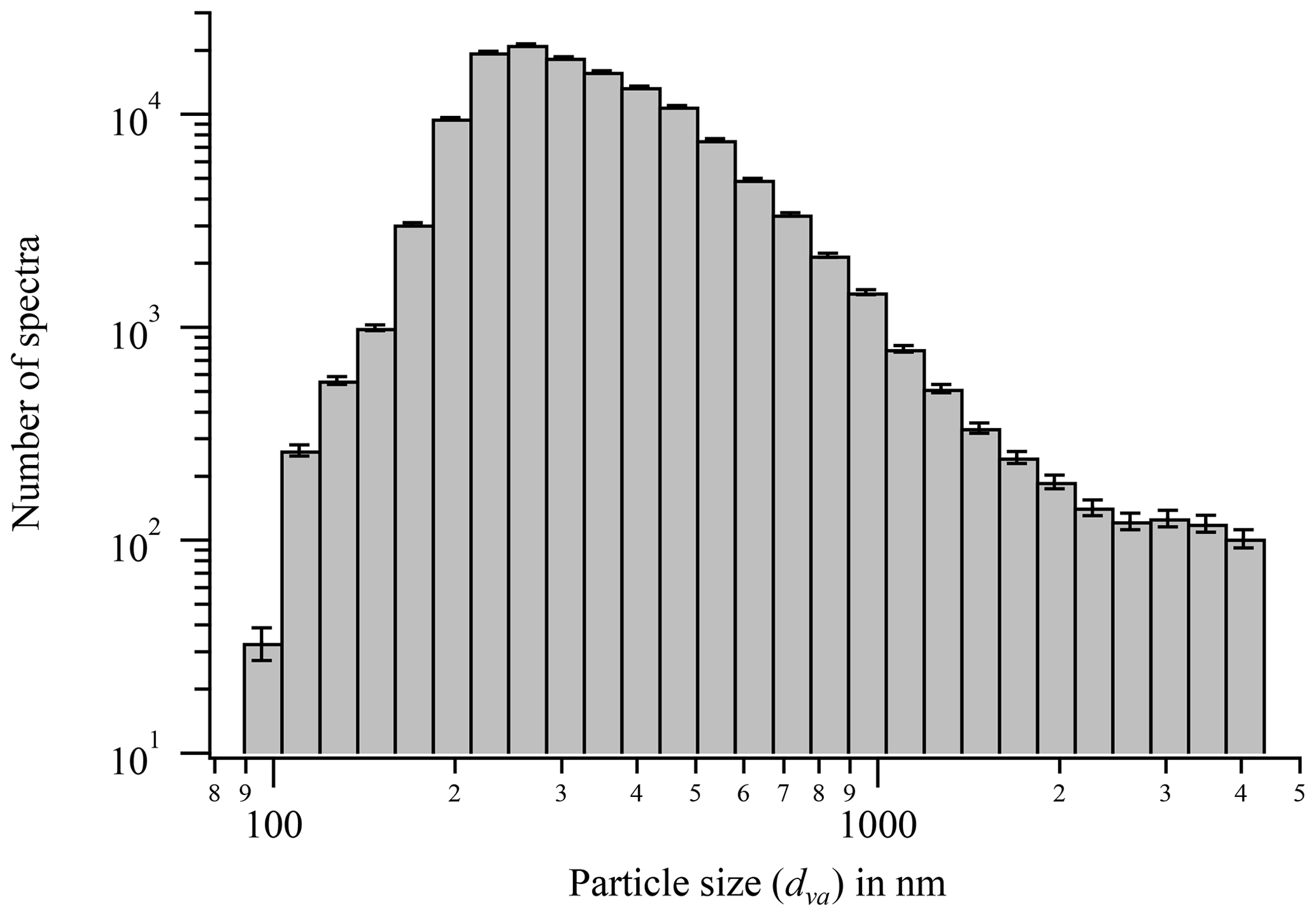
Figure 8Size (vacuum aerodynamic diameter – dva) distribution of single particles calculated by the optical detection system of the ERICA-LAMS during all StratoClim flights (KTM 1–8) performed in Nepal in 2017. This distribution covers particles from the boundary layer up to the stratosphere.
As discussed in Sect. 4.2, the design of the aerosol sampling system plays a key role in the efficiency and quality of aerosol sampling. Murphy et al. (2004) have demonstrated that ice crystals can ablate submicron metal fragments when they impact a sampling inlet during aircraft flights through ice clouds. For the quality control of collected data and the exclusion of artefacts caused by self-contamination during sampling, the surface of the inlet was plated with a chemically inert gold layer, as described in Sect. 4.2. Considering that the abundance of gold in the region of operation is virtually zero, any presence of gold-containing spectra in the recorded data constitutes a strong indication of self-contamination. For this reason and although the aerodynamic design of the inlet reduces the probability of such contamination to a minimum, the recorded data set of single-particle mass spectra was checked for relevant ion markers in order to identify the presence of gold-containing particles.
Gold has only one natural isotope. However, as a result of laser ablation and ionization, both Au+ and Au ions can be detected by the ERICA-LAMS; for detailed information, see the laboratory measurements in Hünig et al. (2022). After an calibration and the generation of unit-resolution mass spectra by means of the evaluation software CRISP (Concise Retrieval of Information from Single Particles; Klimach, 2012), the data set was checked for the Au ion markers +197 and +394. Details on the applied ion marker threshold method can be found in Köllner et al. (2017). The initial results distinguished only one single particle with the spectrum shown in Fig. 9. Apart from the ion markers of interest (Au+ and Au), the signals at +63 (63Cu+) and +65 (65Cu+), as well as −115 (Cu(CN)), −117 (65Cu(CN)), −204 (63Cu2(CN)), and −206 (63Cu65Cu(CN)3) indicate copper fragments as identified by the isotopic ratio. The latter four peaks and the peaks at +72 (Na2CN+), +88 (NaKCN+), −26 (CN−), and −42 (CNO−) indicate cyanide fragments, which occur together with the light metal fragments of sodium and potassium, +23 (Na+) and +39 (K+). Another light metal, Al, is identified by peaks at +27 (Al+), +43 (AlO+) −59 (AlO), and −75 (AlO). The peaks at −249, −339, and −341 are not identified. As a conclusion, it is very likely that these ions might have resulted from a particle that was spalled from the aircraft inlet. This assumption is made based on the fact that, during the electroplating process, the aluminium body of the aircraft inlet was first pickled in a basic zinc solution, then electroplated with a copper layer to enhance adhesion, and finally electroplated with a gold layer. During this process, alkali cyanide (NaCN and KCN) solutions were used.
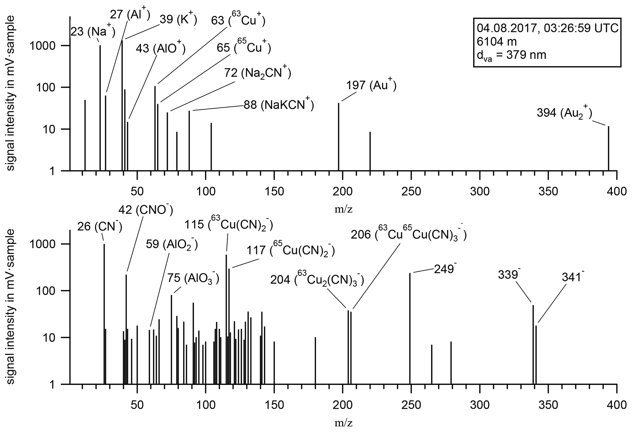
Figure 9Bipolar spectrum from a single particle sampled at a barometric altitude of 6104 m during the KTM 5 flight from Kathmandu, Nepal, on 4 August 2017 indicating gold contamination. Only signals above the ion area peak threshold (7 mV per sample; Hünig et al., 2022) are shown.
Considering that high signals in the raw spectrum can lead to a miscalibration of the peak at +394 (Au), the investigation was afterwards broadened to account for a higher mass calibration tolerance. Therefore, the data set was checked for two marker peaks: the presence of +393 and/or +394. This analysis distinguished 148 single-particle mass spectra from 138 067 recorded spectra during the research flights in Kathmandu, Nepal (KTM 1–8). Noteworthily, these particles were not sampled at a particular altitude, which indicates a random occurrence of the gold-containing particles during the flights. It is also worth mentioning that the occurrence of Au-containing particles is equally distributed over the entire altitude range and cannot be directly associated with either the flight pattern or meteorological events like ice clouds in the area of operation. Nevertheless, the results of the data analysis, targeting gold-containing particles, show that the ERICA-LAMS was capable of measuring gold-containing particles during the StratoClim Asian monsoon phase and that the contamination of the measurements by aircraft inlet fragments was found to be about 0.1 %.
5.4 Aerosol particle chemical composition
To demonstrate the ERICA-LAMS' capability for measuring single particles at high altitudes, a raw spectrum from a single particle collected at a barometric altitude of 19 982 m (GPS altitude 20 431 m) is provided in Fig. 10 as an example. This spectrum is part of the data set presented by Schneider et al. (2021) and constitutes a characteristic example of a particle containing meteoric material. Therein, the distinctive signals of Mg ( 24) and Fe (isotopes at 54 and 56) are evident, while the ions FeO+ ( 72), FeOH+ ( 73), and their hydrated forms (H2O ⋅ FeO+ at 90 and H2O ⋅ FeOH+ at 91) typically occur in the spectra of single particles containing meteoric material (Murphy et al., 1998; Cziczo et al., 2001; Murphy et al., 2014; Schneider et al., 2021) but not in single-particle spectra from mineral or soil dust (Gallavardin et al., 2008). Also, other metal species, such as Na ( 23), Al ( 27), and K ( 39), are common indicators of meteoric material (Murphy et al., 1998; Cziczo et al., 2001; Murphy et al., 2014; Schneider et al., 2021). The anion spectrum is dominated by signals from sulfuric acid fragments, such as SO, SO ( −96), HSO ( −97), H34SO ( −99), HSO4SO ( −177), and H2SO4HSO4 ( −195) (Murphy et al., 1998; Schneider et al., 2021). The signal at −44 can be attributed to the silicate fragment SiO− (Schneider et al., 2021). For the signal at 121, we assume a magnesium–sulfate cluster fragment MgHSO, similar to the ion MgH2SO, as reported by Murphy et al. (2007).
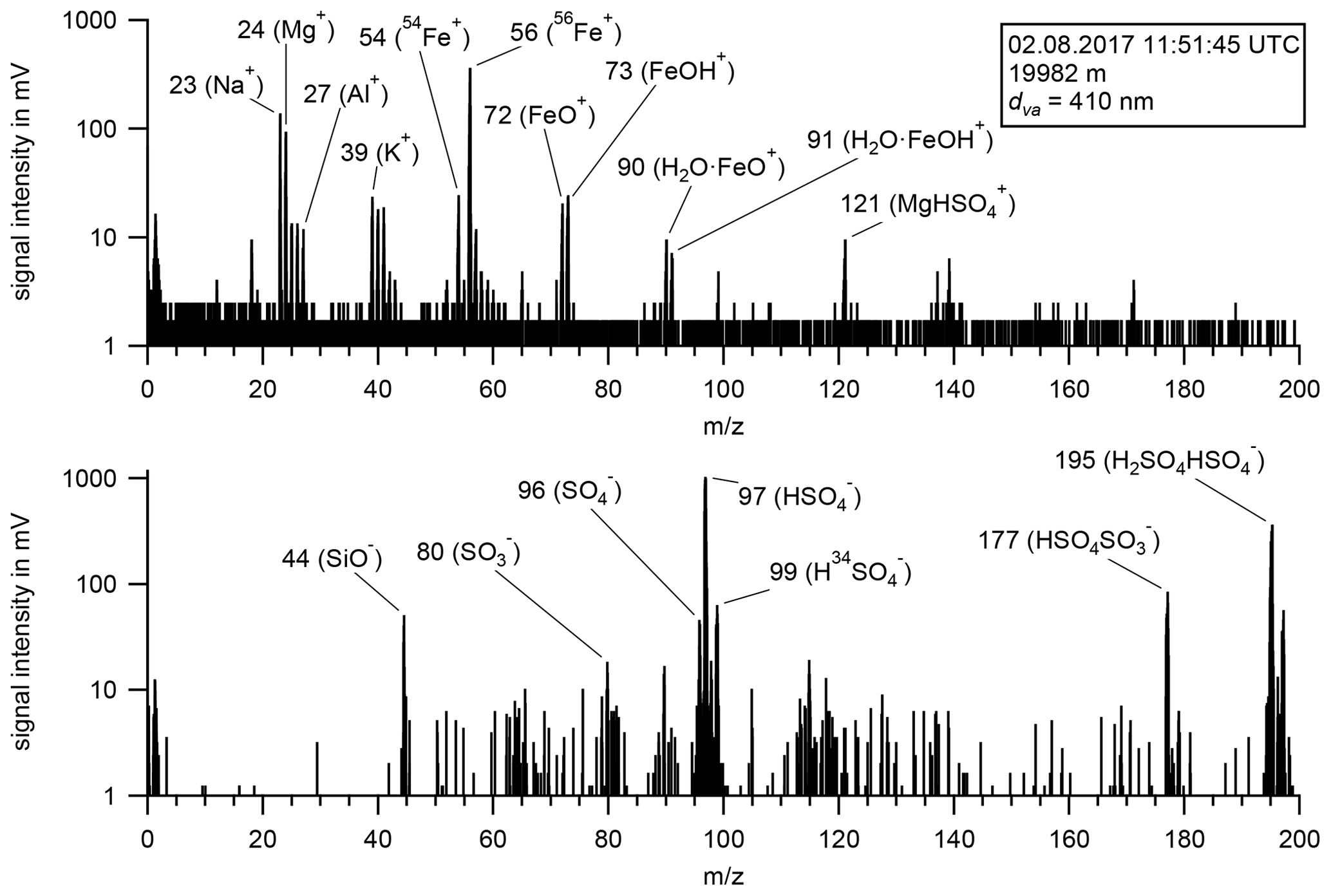
Figure 10Raw bipolar spectrum of an atmospheric single particle containing meteoric material, sampled at 19982 m (barometric altitude, coordinates: 28.6428∘ N, 82.9307∘ E) during StratoClim 2017 (flight KTM 4, 2 August 2017, 11:51:45 UTC; dva=410 nm).
The performance of the ERICA-AMS during a flight (KTM 4, 2 August 2017) is presented in Fig. 11, wherein a continuous measurement of several aerosol species is shown. A varying chemical composition is clearly visible over time. While flying through the tropopause region (from 14:30 to 16:15 local time), enhancement of ammonium, nitrate, and organics can be seen. This is a distinctive feature of the ATAL (Appel et al., 2022), which can be found during the Asian summer monsoon (Vernier et al., 2011). In stratospheric air, almost pure sulfuric acid is found (from 16:30 to 17:35 local time). A detailed analysis of the distribution of chemical species in the Asian monsoon UTLS can be found in Appel et al. (2022).
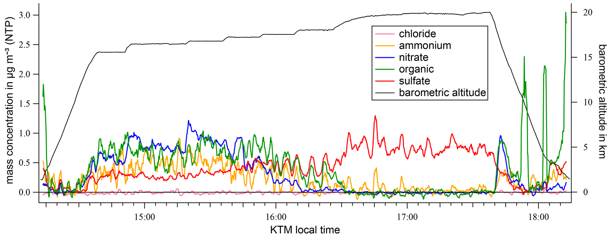
Figure 11Time series of the mass concentrations of different aerosol species recorded and identified by the ERICA-AMS during flight KTM 4 from Kathmandu on 2 August 2017. Data were smoothed with a running mean over 90 s.
Overall, the data produced by the ERICA-LAMS and ERICA-AMS are individually analysed, providing complementary information on the chemical composition of the sampled particles (Hünig et al., 2022; Appel et al., 2022). Additionally, information from other scientific instruments that participated in the StratoClim operations, as well as remote sensing data from collaborating research groups, has been evaluated and correlated with the data produced by the ERICA (Höpfner et al., 2019; Weigel et al., 2021; Mahnke et al., 2021).
After its participation in the StratoClim scientific flights with M-55 Geophysica, the instrument was modified and participated in the ND-MAX–ECLIF 2 campaign organized by NASA (National Aeronautics and Space Administration) and DLR (Deutsches Zentrum für Luft- und Raumfahrt (German Aerospace Center)), flying aboard the NASA DC-8 Airborne Science Laboratory in the United States and Germany in early 2018 (Schneider et al., 2021). In that configuration, an optical particle counter (SkyOPC 11-S, Grimm) together with an external pump was added to the ERICA instrument rack and shared the same aerosol sampling inlet. This addition provides complementary size distribution information for particles with diameters larger than 250 nm. More recently, the instrument was further modified and adapted to the payload of the NSF/NCAR HIAPER Gulfstream GV aircraft. The instrument successfully operated in test flights, which were performed in the United States in 2020, and participated in the NASA–NCAR ACCLIP campaign, which took place in South Korea in the summer of 2022. In this setup, apart from the previously added optical particle counter, the ERICA also controlled an external aerosol impaction setup, which shared the same inlet and collected aerosol samples on multiple discrete impaction substrates during the flights. It is worth mentioning that both aircraft, the DC-8 and Gulfstream GV, operate at lower altitudes than the M-55 Geophysica, and on these occasions, the ERICA was installed in a pressurized cabin and operated in the presence of an on-board scientist/operator. As these factors place these applications of the ERICA outside the scope of this paper, these flight operations are not discussed in detail here.
Apart from its integration into other platforms, the instrument has undergone several modifications and improvements. This includes changes in its vacuum and electrical systems and the development of new software and new measurement techniques. One such noteworthy upgrade is the introduction of a single-particle mass spectrometry mode for the ERICA-AMS, which exploits the optical detection system of the ERICA-LAMS. The performance of this new mode of operation is currently under investigation.
The ERICA is an aerosol particle mass spectrometer that is capable of simultaneously producing both bipolar spectra from refractory and non-refractory single aerosol particles using LDI and averaged spectra using TD-EI on non-refractory aerosol particles. It is especially designed for in situ, real-time chemical composition analysis of aerosols in the absence of an instrument operator as it can operate completely autonomously. Moreover, its design has enabled its operation under harsh conditions, like those experienced in the UTLS, aboard unpressurized high-altitude research aircraft.
The instrument successfully participated in the aircraft operations of the StratoClim project flying aboard the M-55 Geophysica high-altitude research aircraft, operating continuously during all 11 scientific flights in sub-tropical and tropical latitudes in southern Europe and Asia. The instrument exhibited a stable performance under a wide range of flight and environmental conditions. Most importantly, flying inside the AMA system, the ERICA collected chemical composition information for aerosols sampled from the ATAL, constituting the first in situ measurements of this kind. This comprehensive set of data was the result of the simultaneous and complementary operation of the ERICA-LAMS and the ERICA-AMS, which otherwise would have only been possible with the deployment of two separate instruments on board.
The ERICA remains under continuous development and is undergoing several improvements. Its modular and relatively compact design facilitates its adaptation and operation on other platforms. As of 2022, the ERICA has also operated aboard the NASA DC-8 Airborne Science Laboratory and the NSF/NCAR HIAPER aircraft.
| ALABAMA | Aircraft-based Laser Ablation Aerosol |
| Mass Spectrometer | |
| AMA | Asian monsoon anticyclone |
| AMS | Aerosol mass spectrometer |
| ATAL | Asian tropopause aerosol layer |
| CARIBIC | Civil Aircraft for the Regular |
| Investigation of the atmosphere | |
| Based on an Instrumented Container | |
| C-ToF-AMS | Compact time-of-flight aerosol |
| mass spectrometer | |
| CW | Continuous wave |
| DLR | Deutsches Zentrum für Luft- und |
| Raumfahrt (German Aerospace Center) | |
| EEPROM | Electrically erasable programmable |
| read-only memory | |
| ERC | European Research Council |
| ERICA | ERC Instrument for the Chemical |
| composition of Aerosols | |
| ERICA-AMS | ERICA aerosol mass spectrometer |
| ERICA-LAMS | ERICA laser-ablation mass |
| spectrometer | |
| GPU | Ground power unit |
| GUI | Graphical user interface |
| HV | High voltage |
| KLX | Kalamata (airport/flight) |
| KTM | Kathmandu (airport/flight) |
| LAN | Local area network |
| LDI | Laser desorption and ionization |
| LPM | Low-power mode |
| MCP | Microchannel plate |
| MOSFET | Metal-oxide-semiconductor |
| field-effect transistor | |
| NASA | National Aeronautics and Space |
| Administration (USA) | |
| NCAR | National Center for Atmospheric |
| Research (USA) | |
| Nd:YAG | Neodymium-doped yttrium |
| aluminium garnet | |
| PC | Personal computer |
| PID | Proportional–integral–derivative |
| PMT | Photomultiplier tube |
| PV | Pressure vessel |
| RTD | Resistance temperature detector |
| SBD | Short-burst data |
| SP-MS | Single-particle mass spectrometer |
| TD-EI | Thermal desorption–electron |
| impact ionization | |
| ToF | Time-of-flight |
| UCSE | Unit for connection with scientific |
| equipment | |
| UPS | Uninterruptible power supply |
| USB | Universal serial bus |
| UTLS | Upper troposphere and lower |
| stratosphere |
Data shown in Figs. 9 and 10 are available at https://doi.org/10.5281/zenodo.6968792 (Dragoneas et al., 2022).
The supplement related to this article is available online at: https://doi.org/10.5194/amt-15-5719-2022-supplement.
SB provided the instrumental concept and an initial design in his ERC Advanced Grant proposal. SB, FD, and JS initiated the instrumental design and accompanied its development and characterization. AD, OA, SM, AH, and TB designed and developed several constituent parts of the instrument and assembled all of its sub-systems into an integrated system, which they finally adapted to the aircraft. MH made the flow calculations for the development of the aerosol sampling system. OA, AH, AD, SM, TB, SB, and RW participated in the field campaigns in Greece and Nepal, where they prepared, calibrated, and operated the instrument. SM and AD evaluated the system performance data. AH and OA evaluated the mass spectrometry data. AD, together with SB, SM, OA, and AH, drafted the manuscript. All co-authors read and provided detailed comments on the manuscript.
At least one of the (co-)authors is a member of the editorial board of Atmospheric Measurement Techniques. The peer-review process was guided by an independent editor, and the authors also have no other competing interests to declare.
Publisher’s note: Copernicus Publications remains neutral with regard to jurisdictional claims in published maps and institutional affiliations.
Regarding the technical development of the ERICA, we would like to acknowledge the contribution of the mechanical workshops of Johannes Gutenberg University Mainz and MPIC and the Instrument Development and Electronics Department of MPIC for their valuable contribution to the development of the instrument. Furthermore, we would like to express our gratitude to Urs Rohner from Tofwerk AG for the technical support he has provided.
Regarding the field campaign organization, we would like to acknowledge the efforts of the organizational team of the StratoClim project and, especially, Fred Stroh from Forschungszentrum Jülich. We would like to thank the pilots and the ground crew of the M-55 Geophysica for conducting the test and research flights. Also, we should acknowledge the contribution of the Civil Aviation Authority of Nepal and the support of the employees of Buddha Air during the aircraft operations which were hosted at the Buddha Air hangar of Tribhuvan International Airport in July and August 2017. Finally, we would like to thank the Hellenic Air Force and the Hellenic Civil Aviation Authority for their co-operation in the organization of the first aircraft campaign of the StratoClim project; especially, we would like to give credit to Konstantinos Chinis (wing commander), Alexandros Kefalas (wing deputy commander), Ioannis Kitsios (MRO director), and the rest of the personnel of the 120 Air Training Wing in Kalamata, Greece, for providing their valuable support during the field campaign that took place at their air base in August and September 2016.
This research has been supported the Max Planck Society, the European Research Council under the European Union's Seventh Framework Program (FP7/2007–2013) (EXCATRO (grant no. 321040) and StratoClim (grant no. 603557)), and the German Federal Ministry of Education and Research (BMBF) under the joint ROMIC-project SPITFIRE (01LG1205A).
The article processing charges for this open-access publication were covered by the Max Planck Society.
This paper was edited by Jessie Creamean and reviewed by three anonymous referees.
Allan, J. D., Jimenez, J. L., Williams, P. I., Alfarra, M. R., Bower, K. N., Jayne, J. T., Coe, H., and Worsnop, D. R.: Quantitative sampling using an Aerodyne aerosol mass spectrometer 1. Techniques of data interpretation and error analysis, J. Geophys. Res., 108, 4090, https://doi.org/10.1029/2002JD002358, 2003.
Allen, J. O., Fergenson, D. P., Gard, E. E., Hughes, L. S., Morrical, B. D., Kleeman, M. J., Gross, D. S., Gälli, M. E., Prather, K. A., and Cass, G. R.: Particle Detection Efficiencies of Aerosol Time of Flight Mass Spectrometers under Ambient Sampling Conditions, Environ. Sci. Technol., 34, 211–217, https://doi.org/10.1021/es9904179, 2000.
Appel, O., Köllner, F., Dragoneas, A., Hünig, A., Molleker, S., Schlager, H., Mahnke, C., Weigel, R., Port, M., Schulz, C., Drewnick, F., Vogel, B., Stroh, F., and Borrmann, S.: Chemical analysis of the Asian Tropopause Aerosol Layer (ATAL) with emphasis on secondary aerosol particles using aircraft based in situ aerosol mass spectrometry, Atmos. Chem. Phys. Discuss. [preprint], https://doi.org/10.5194/acp-2022-92, in review, 2022.
Borrmann, S.: High altitude atmospheric observation, in: McGraw-Hill Yearbook of Science & Technology 2005, McGraw-Hill, New York, 137–139, ISBN: 0071445048, ISSN: 0076-2016, 2005.
Borrmann, S., Kunkel, D., Weigel, R., Minikin, A., Deshler, T., Wilson, J. C., Curtius, J., Volk, C. M., Homan, C. D., Ulanovsky, A., Ravegnani, F., Viciani, S., Shur, G. N., Belyaev, G. V., Law, K. S., and Cairo, F.: Aerosols in the tropical and subtropical UT/LS: in-situ measurements of submicron particle abundance and volatility, Atmos. Chem. Phys., 10, 5573–5592, https://doi.org/10.5194/acp-10-5573-2010, 2010.
Brands, M., Kamphus, M., Böttger, T., Schneider, J., Drewnick, F., Roth, A., Curtius, J., Voigt, C., Borbon, A., Beekmann, M., Bourdon, A., Perrin, T., and Borrmann, S.: Characterization of a Newly Developed Aircraft-Based Laser Ablation Aerosol Mass Spectrometer (ALABAMA) and First Field Deployment in Urban Pollution Plumes over Paris During MEGAPOLI 2009, Aerosol Sci. Tech., 45, 46–64, https://doi.org/10.1080/02786826.2010.517813, 2011.
Brenninkmeijer, C. A. M., Crutzen, P., Boumard, F., Dauer, T., Dix, B., Ebinghaus, R., Filippi, D., Fischer, H., Franke, H., Frieβ, U., Heintzenberg, J., Helleis, F., Hermann, M., Kock, H. H., Koeppel, C., Lelieveld, J., Leuenberger, M., Martinsson, B. G., Miemczyk, S., Moret, H. P., Nguyen, H. N., Nyfeler, P., Oram, D., O'Sullivan, D., Penkett, S., Platt, U., Pupek, M., Ramonet, M., Randa, B., Reichelt, M., Rhee, T. S., Rohwer, J., Rosenfeld, K., Scharffe, D., Schlager, H., Schumann, U., Slemr, F., Sprung, D., Stock, P., Thaler, R., Valentino, F., van Velthoven, P., Waibel, A., Wandel, A., Waschitschek, K., Wiedensohler, A., Xueref-Remy, I., Zahn, A., Zech, U., and Ziereis, H.: Civil Aircraft for the regular investigation of the atmosphere based on an instrumented container: The new CARIBIC system, Atmos. Chem. Phys., 7, 4953–4976, https://doi.org/10.5194/acp-7-4953-2007, 2007.
Brown, R. S. and Lennon, J. J.: Mass Resolution Improvement by Incorporation of Pulsed Ion Extraction in a Matrix-Assisted Laser Desorption/Ionization Linear Time-of-Flight Mass Spectrometer, Anal. Chem., 67, 1998–2003, https://doi.org/10.1021/ac00109a015, 1995.
Canagaratna, M. R., Jayne, J. T., Jimenez, J. L., Allan, J. D., Alfarra, M. R., Zhang, Q., Onasch, T. B., Drewnick, F., Coe, H., Middlebrook, A., Delia, A., Williams, L. R., Trimborn, A. M., Northway, M. J., DeCarlo, P. F., Kolb, C. E., Davidovits, P., and Worsnop, D. R.: Chemical and microphysical characterization of ambient aerosols with the aerodyne aerosol mass spectrometer, Mass Spectrom. Rev., 26, 185–222, https://doi.org/10.1002/mas.20115, 2007.
Cziczo, D. J., Thomson, D. S., and Murphy, D. M.: Ablation, flux, and atmospheric implications of meteors inferred from stratospheric aerosol, Science, 291, 1772–1775, https://doi.org/10.1126/science.1057737, 2001.
Dahneke, B.: Sampling and analysis of suspended particles and vapors by continuum source particle beams, AIChE Symposium Series, 76, 134–143, 1980.
Dragoneas, A., Molleker, S., Appel, O., Hünig, A., Böttger, T., Hermann, M., Drewnick, F., Schneider, J., Weigel, R., and Borrmann, S.: The realization of autonomous, aircraft-based, real-time aerosol mass spectrometry in the upper troposphere and lower stratosphere (dataset), Zenodo [data set], https://doi.org/10.5281/zenodo.6968792, 2022.
Drewnick, F., Hings, S. S., DeCarlo, P., Jayne, J. T., Gonin, M., Fuhrer, K., Weimer, S., Jimenez, J. L., Demerjian, K. L., Borrmann, S., and Worsnop, D. R.: A New Time-of-Flight Aerosol Mass Spectrometer (TOF-AMS) – Instrument Description and First Field Deployment, Aerosol Sci. Tech., 39, 637–658, https://doi.org/10.1080/02786820500182040, 2005.
Formenti, P., Vaughan, G., Krämer, M., Fierli, F., MacKenzie, R., Harris, N., and Stiller, G.: StratoClim stratospheric and upper tropospheric processes for better climate predictions (ACP/AMT inter-journal SI), Atmos. Chem. Phys., https://acp.copernicus.org/articles/special_issue1012.html (last access: 1 October 2022), 2015.
Frey, W., Borrmann, S., Fierli, F., Weigel, R., Mitev, V., Matthey, R., Ravegnani, F., Sitnikov, N. M., Ulanovsky, A., and Cairo, F.: Tropical deep convective life cycle: Cb-anvil cloud microphysics from high-altitude aircraft observations, Atmos. Chem. Phys., 14, 13223–13240, https://doi.org/10.5194/acp-14-13223-2014, 2014.
Froyd, K. D., Murphy, D. M., Sanford, T. J., Thomson, D. S., Wilson, J. C., Pfister, L., and Lait, L.: Aerosol composition of the tropical upper troposphere, Atmos. Chem. Phys., 9, 4363–4385, https://doi.org/10.5194/acp-9-4363-2009, 2009.
Gallavardin, S. J., Froyd, K. D., Lohmann, U., Moehler, O., Murphy, D. M., and Cziczo, D. J.: Single Particle Laser Mass Spectrometry Applied to Differential Ice Nucleation Experiments at the AIDA Chamber, Aerosol Sci. Tech., 42, 773–791, https://doi.org/10.1080/02786820802339538, 2008.
Gemayel, R., Hellebust, S., Temime-Roussel, B., Hayeck, N., Van Elteren, J. T., Wortham, H., and Gligorovski, S.: The performance and the characterization of laser ablation aerosol particle time-of-flight mass spectrometry (LAAP-ToF-MS), Atmos. Meas. Tech., 9, 1947–1959, https://doi.org/10.5194/amt-9-1947-2016, 2016.
Hermann, M., Weigelt, A., Assmann, D., Pfeifer, S., Müller, T., Conrath, T., Voigtländer, J., Heintzenberg, J., Wiedensohler, A., Martinsson, B. G., Deshler, T., Brenninkmeijer, C. A. M., and Zahn, A.: An optical particle size spectrometer for aircraft-borne measurements in IAGOS-CARIBIC, Atmos. Meas. Tech., 9, 2179–2194, https://doi.org/10.5194/amt-9-2179-2016, 2016.
Höpfner, M., Ungermann, J., Borrmann, S., Wagner, R., Spang, R., Riese, M., Stiller, G., Appel, O., Batenburg, A. M., Bucci, S., Cairo, F., Dragoneas, A., Friedl-Vallon, F., Hunig, A., Johansson, S., Krasauskas, L., Legras, B., Leisner, T., Mahnke, C., Mohler, O., Molleker, S., Muller, R., Neubert, T., Orphal, J., Preusse, P., Rex, M., Saathoff, H., Stroh, F., Weigel, R., and Wohltmann, I.: Ammonium nitrate particles formed in upper troposphere from ground ammonia sources during Asian monsoons, Nat. Geosci., 12, 608–612, https://doi.org/10.1038/s41561-019-0385-8, 2019.
Hünig, A.: Development, characterization, and first field deployments of a novel aerosol mass spectrometer combining laser ablation and flash vaporization techniques for aircraft application at high altitudes, FB 09 Chemie, Pharmazie u. Geowissenschaft, Johannes Gutenberg-Universität Mainz, Mainz, dissertation, https://doi.org/10.25358/openscience-5554, 2021.
Hünig, A., Appel, O., Dragoneas, A., Molleker, S., Clemen, H.-C., Helleis, F., Klimach, T., Köllner, F., Böttger, T., Drewnick, F., Schneider, J., and Borrmann, S.: Design, characterization, and first field deployment of a novel aircraft-based aerosol mass spectrometer combining the laser ablation and flash vaporization techniques, Atmos. Meas. Tech., 15, 2889–2921, https://doi.org/10.5194/amt-15-2889-2022, 2022.
Jayne, J. T., Leard, D. C., Zhang, X., Davidovits, P., Smith, K. A., Kolb, C. E., and Worsnop, D. R.: Development of an Aerosol Mass Spectrometer for Size and Composition Analysis of Submicron Particles, Aerosol Sci. Tech., 33, 49–70, https://doi.org/10.1080/027868200410840, 2000.
Klimach, T.: Chemische Zusammensetzung der Aerosole – Design und Datenauswertung eines Einzelpartikel-Laserablationsmassenspektrometers, PhD thesis, Johannes Gutenberg-Universität Mainz, Mainz, Germany, https://doi.org/10.25358/openscience-4386, 2012 (in German).
Köllner, F., Schneider, J., Willis, M. D., Klimach, T., Helleis, F., Bozem, H., Kunkel, D., Hoor, P., Burkart, J., Leaitch, W. R., Aliabadi, A. A., Abbatt, J. P. D., Herber, A. B., and Borrmann, S.: Particulate trimethylamine in the summertime Canadian high Arctic lower troposphere, Atmos. Chem. Phys., 17, 13747–13766, https://doi.org/10.5194/acp-17-13747-2017, 2017.
Krämer, M., Twohy, C., Hermann, M., Afchine, A., Dhaniyala, S. and Korolev, A.: Aerosol and Cloud Particle Sampling, chap. 6, in: Airborne Measurements for Environmental Research: Methods and Instruments, edited by: Kokhanovsky, A., Wendisch, M., and Brenguier, J.-L., John Wiley & Sons, Ltd, 303–341, https://doi.org/10.1002/9783527653218, 2013.
Mahnke, C., Weigel, R., Cairo, F., Vernier, J.-P., Afchine, A., Krämer, M., Mitev, V., Matthey, R., Viciani, S., D'Amato, F., Ploeger, F., Deshler, T., and Borrmann, S.: The Asian tropopause aerosol layer within the 2017 monsoon anticyclone: microphysical properties derived from aircraft-borne in situ measurements, Atmos. Chem. Phys., 21, 15259–15282, https://doi.org/10.5194/acp-21-15259-2021, 2021.
Molleker, S., Borrmann, S., Schlager, H., Luo, B., Frey, W., Klingebiel, M., Weigel, R., Ebert, M., Mitev, V., Matthey, R., Woiwode, W., Oelhaf, H., Dörnbrack, A., Stratmann, G., Grooß, J.-U., Günther, G., Vogel, B., Müller, R., Krämer, M., Meyer, J., and Cairo, F.: Microphysical properties of synoptic-scale polar stratospheric clouds: in situ measurements of unexpectedly large HNO3-containing particles in the Arctic vortex, Atmos. Chem. Phys., 14, 10785–10801, https://doi.org/10.5194/acp-14-10785-2014, 2014.
Molleker, S., Helleis, F., Klimach, T., Appel, O., Clemen, H.-C., Dragoneas, A., Gurk, C., Hünig, A., Köllner, F., Rubach, F., Schulz, C., Schneider, J., and Borrmann, S.: Application of an O-ring pinch device as a constant-pressure inlet (CPI) for airborne sampling, Atmos. Meas. Tech., 13, 3651–3660, https://doi.org/10.5194/amt-13-3651-2020, 2020.
Murphy, D. M. and Thomson, D. S.: Laser Ionization Mass Spectroscopy of Single Aerosol Particles, Aerosol Sci. Tech., 22, 237–249, https://doi.org/10.1080/02786829408959743, 1995.
Murphy, D. M., Thomson, D. S., and Mahoney, M. J.: In Situ Measurements of Organics, Meteoritic Material, Mercury, and Other Elements in Aerosols at 5 to 19 Kilometers, Science, 282, 1664–1669, https://doi.org/10.1126/science.282.5394.1664, 1998.
Murphy, D. M., Cziczo, D. J., Hudson, P. K., Thomson, D. S., Wilson, J. C., Kojima, T., and Buseck, P. R.: Particle generation and resuspension in aircraft inlets when flying in clouds, Aerosol Sci. Tech., 38, 400–408, https://doi.org/10.1080/02786820490443094, 2004.
Murphy, D. M., Cziczo, D. J., Froyd, K. D., Hudson, P. K., Matthew, B. M., Middlebrook, A. M., Peltier, R. E., Sullivan, A., Thomson, D. S., and Weber, R. J.: Single-particle mass spectrometry of tropospheric aerosol particles, J. Geophys. Res., 111, D23S32, https://doi.org/10.1029/2006JD007340, 2006.
Murphy, D. M., Cziczo, D. J., Hudson, P. K., and Thomson, D. S.: Carbonaceous material in aerosol particles in the lower stratosphere and tropopause region, J. Geophys. Res., 112, D04203, https://doi.org/10.1029/2006jd007297, 2007.
Murphy, D. M., Froyd, K. D., Schwarz, J. P., and Wilson, J. C.: Observations of the chemical composition of stratospheric aerosol particles, Q. J. Roy. Meteor. Soc., 140, 1269–1278, https://doi.org/10.1002/qj.2213, 2014.
Noble, C. A., Nordmeyer, T., Salt, K., Morrical, B., and Prather, K. A.: Aerosol characterization using mass spectrometry, TrAC – Trend. Anal. Chem., 13, 218–222, https://doi.org/10.1016/0165-9936(94)85042-9, 1994.
Peck, J., Gonzalez, L. A., Williams, L. R., Xu, W., Croteau, P. L., Timko, M. T., Jayne, J. T., Worsnop, D. R., Miake-Lye, R. C., and Smith, K. A.: Development of an aerosol mass spectrometer lens system for PM2.5, Aerosol Sci. Tech., 50, 781–789, https://doi.org/10.1080/02786826.2016.1190444, 2016.
Pratt, K. A., Mayer, J. E., Holecek, J. C., Moffet, R. C., Sanchez, R. O., Rebotier, T. P., Furutani, H., Gonin, M., Fuhrer, K., Su, Y., Guazzotti, S., and Prather, K. A.: Development and Characterization of an Aircraft Aerosol Time-of-Flight Mass Spectrometer, Anal. Chem., 81, 1792–1800, https://doi.org/10.1021/ac801942r, 2009.
Reilly, P. T. A., Lazar, A. C., Gieray, R. A., Whitten, W. B., and Ramsey, J. M.: The Elucidation of Charge-Transfer-Induced Matrix Effects in Environmental Aerosols Via Real-Time Aerosol Mass Spectral Analysis of Individual Airborne Particles, Aerosol Sci. Tech., 33, 135–152, https://doi.org/10.1080/027868200410895, 2000.
Schneider, J., Weigel, R., Klimach, T., Dragoneas, A., Appel, O., Hünig, A., Molleker, S., Köllner, F., Clemen, H.-C., Eppers, O., Hoppe, P., Hoor, P., Mahnke, C., Krämer, M., Rolf, C., Grooß, J.-U., Zahn, A., Obersteiner, F., Ravegnani, F., Ulanovsky, A., Schlager, H., Scheibe, M., Diskin, G. S., DiGangi, J. P., Nowak, J. B., Zöger, M., and Borrmann, S.: Aircraft-based observation of meteoric material in lower-stratospheric aerosol particles between 15 and 68∘ N, Atmos. Chem. Phys., 21, 989–1013, https://doi.org/10.5194/acp-21-989-2021, 2021.
Schulz, C., Schneider, J., Amorim Holanda, B., Appel, O., Costa, A., de Sá, S. S., Dreiling, V., Fütterer, D., Jurkat-Witschas, T., Klimach, T., Knote, C., Krämer, M., Martin, S. T., Mertes, S., Pöhlker, M. L., Sauer, D., Voigt, C., Walser, A., Weinzierl, B., Ziereis, H., Zöger, M., Andreae, M. O., Artaxo, P., Machado, L. A. T., Pöschl, U., Wendisch, M., and Borrmann, S.: Aircraft-based observations of isoprene-epoxydiol-derived secondary organic aerosol (IEPOX-SOA) in the tropical upper troposphere over the Amazon region, Atmos. Chem. Phys., 18, 14979–15001, https://doi.org/10.5194/acp-18-14979-2018, 2018.
Shen, X., Ramisetty, R., Mohr, C., Huang, W., Leisner, T., and Saathoff, H.: Laser ablation aerosol particle time-of-flight mass spectrometer (LAAPTOF): performance, reference spectra and classification of atmospheric samples, Atmos. Meas. Tech., 11, 2325–2343, https://doi.org/10.5194/amt-11-2325-2018, 2018.
Stefanutti, L., Di Donfrancesco, G., and Cairo, F.: Airborne Instrumentation for Aerosol Measurements, in: Encyclopedia of Analytical Chemistry, edited by: Meyers, R. A., John Wiley & Sons, Ltd., https://doi.org/10.1002/9780470027318.a0703.pub2, 2009.
Steiner, W. E., Clowers, B. H., Fuhrer, K., Gonin, M., Matz Laura, M., Siems William, F., Schultz Albert, J., and Hill Herbert, H.: Electrospray ionization with ambient pressure ion mobility separation and mass analysis by orthogonal time-of-flight mass spectrometry, Rapid Commun. Mass Sp., 15, 2221–2226, https://doi.org/10.1002/rcm.495, 2001.
Vernier, J. P., Thomason, L. W., and Kar, J.: CALIPSO detection of an Asian tropopause aerosol layer, Geophys. Res. Lett., 38, L07804, https://doi.org/10.1029/2010gl046614, 2011.
Voigt, C., Schreiner, J., Kohlmann, A., Zink, P., Mauersberger, K., Larsen, N., Deshler, T., Kröger, C., Rosen, J., Adriani, A., Cairo, F., Donfrancesco, G. D., Viterbini, M., Ovarlez, J., Ovarlez, H., David, C., and Dörnbrack, A.: Nitric Acid Trihydrate (NAT) in Polar Stratospheric Clouds, Science, 290, 1756–1758, https://doi.org/10.1126/science.290.5497.1756, 2000.
Voigt, C., Schumann, U., Minikin, A., Abdelmonem, A., Afchine, A., Borrmann, S., Boettcher, M., Buchholz, B., Bugliaro, L., Costa, A., Curtius, J., Dollner, M., Dörnbrack, A., Dreiling, V., Ebert, V., Ehrlich, A., Fix, A., Forster, L., Frank, F., Fütterer, D., Giez, A., Graf, K., Grooß, J.-U., Groß, S., Heimerl, K., Heinold, B., Hüneke, T., Järvinen, E., Jurkat, T., Kaufmann, S., Kenntner, M., Klingebiel, M., Klimach, T., Kohl, R., Krämer, M., Krisna, T. C., Luebke, A., Mayer, B., Mertes, S., Molleker, S., Petzold, A., Pfeilsticker, K., Port, M., Rapp, M., Reutter, P., Rolf, C., Rose, D., Sauer, D., Schäfler, A., Schlage, R., Schnaiter, M., Schneider, J., Spelten, N., Spichtinger, P., Stock, P., Walser, A., Weigel, R., Weinzierl, B., Wendisch, M., Werner, F., Wernli, H., Wirth, M., Zahn, A., Ziereis, H., and Zöger, M.: ML-CIRRUS: The Airborne Experiment on Natural Cirrus and Contrail Cirrus with the High-Altitude Long-Range Research Aircraft HALO, B. Am. Meteorol. Soc., 98, 271–288, https://doi.org/10.1175/BAMS-D-15-00213.1, 2016.
von der Weiden, S.-L., Drewnick, F., and Borrmann, S.: Particle Loss Calculator – a new software tool for the assessment of the performance of aerosol inlet systems, Atmos. Meas. Tech., 2, 479–494, https://doi.org/10.5194/amt-2-479-2009, 2009.
von Hobe, M., Bekki, S., Borrmann, S., Cairo, F., D'Amato, F., Di Donfrancesco, G., Dörnbrack, A., Ebersoldt, A., Ebert, M., Emde, C., Engel, I., Ern, M., Frey, W., Genco, S., Griessbach, S., Grooß, J.-U., Gulde, T., Günther, G., Hösen, E., Hoffmann, L., Homonnai, V., Hoyle, C. R., Isaksen, I. S. A., Jackson, D. R., Jánosi, I. M., Jones, R. L., Kandler, K., Kalicinsky, C., Keil, A., Khaykin, S. M., Khosrawi, F., Kivi, R., Kuttippurath, J., Laube, J. C., Lefèvre, F., Lehmann, R., Ludmann, S., Luo, B. P., Marchand, M., Meyer, J., Mitev, V., Molleker, S., Müller, R., Oelhaf, H., Olschewski, F., Orsolini, Y., Peter, T., Pfeilsticker, K., Piesch, C., Pitts, M. C., Poole, L. R., Pope, F. D., Ravegnani, F., Rex, M., Riese, M., Röckmann, T., Rognerud, B., Roiger, A., Rolf, C., Santee, M. L., Scheibe, M., Schiller, C., Schlager, H., Siciliani de Cumis, M., Sitnikov, N., Søvde, O. A., Spang, R., Spelten, N., Stordal, F., Sumińska-Ebersoldt, O., Ulanovski, A., Ungermann, J., Viciani, S., Volk, C. M., vom Scheidt, M., von der Gathen, P., Walker, K., Wegner, T., Weigel, R., Weinbruch, S., Wetzel, G., Wienhold, F. G., Wohltmann, I., Woiwode, W., Young, I. A. K., Yushkov, V., Zobrist, B., and Stroh, F.: Reconciliation of essential process parameters for an enhanced predictability of Arctic stratospheric ozone loss and its climate interactions (RECONCILE): activities and results, Atmos. Chem. Phys., 13, 9233–9268, https://doi.org/10.5194/acp-13-9233-2013, 2013.
Weigel, R., Hermann, M., Curtius, J., Voigt, C., Walter, S., Böttger, T., Lepukhov, B., Belyaev, G., and Borrmann, S.: Experimental characterization of the COndensation PArticle counting System for high altitude aircraft-borne application, Atmos. Meas. Tech., 2, 243–258, https://doi.org/10.5194/amt-2-243-2009, 2009.
Weigel, R., Borrmann, S., Kazil, J., Minikin, A., Stohl, A., Wilson, J. C., Reeves, J. M., Kunkel, D., de Reus, M., Frey, W., Lovejoy, E. R., Volk, C. M., Viciani, S., D'Amato, F., Schiller, C., Peter, T., Schlager, H., Cairo, F., Law, K. S., Shur, G. N., Belyaev, G. V., and Curtius, J.: In situ observations of new particle formation in the tropical upper troposphere: the role of clouds and the nucleation mechanism, Atmos. Chem. Phys., 11, 9983–10010, https://doi.org/10.5194/acp-11-9983-2011, 2011.
Weigel, R., Volk, C. M., Kandler, K., Hösen, E., Günther, G., Vogel, B., Grooß, J.-U., Khaykin, S., Belyaev, G. V., and Borrmann, S.: Enhancements of the refractory submicron aerosol fraction in the Arctic polar vortex: feature or exception?, Atmos. Chem. Phys., 14, 12319–12342, https://doi.org/10.5194/acp-14-12319-2014, 2014.
Weigel, R., Mahnke, C., Baumgartner, M., Dragoneas, A., Vogel, B., Ploeger, F., Viciani, S., D'Amato, F., Bucci, S., Legras, B., Luo, B., and Borrmann, S.: In situ observation of new particle formation (NPF) in the tropical tropopause layer of the 2017 Asian monsoon anticyclone – Part 1: Summary of StratoClim results, Atmos. Chem. Phys., 21, 11689–11722, https://doi.org/10.5194/acp-21-11689-2021, 2021.
- Abstract
- Introduction
- ERICA instrument design
- The aircraft
- Technical integration
- Application and performance of the instrument in the UTLS
- Further deployments and upgrades
- Summary
- Appendix A: Acronyms and abbreviations
- Data availability
- Author contributions
- Competing interests
- Disclaimer
- Acknowledgements
- Financial support
- Review statement
- References
- Supplement