
the Creative Commons Attribution 4.0 License.
the Creative Commons Attribution 4.0 License.
 | 06 Oct 2026
Estimating beam pointing of vertically pointing cloud radars using radiosonde measurements

Scott E. Giangrande
Adam K. Theisen
Karen L. Johnson
Iosif A. Lindenmaier
Timothy G. Wendler
Jennifer Comstock
Marquette Rocque
Alyssa Matthews
Accurate beam pointing is essential for vertically pointing cloud radars, as even small tilts away from zenith introduce projections of horizontal wind into Doppler velocity measurements. These effects can bias the interpretation of vertical air motion and hydrometeor fall speeds, leading to systematic errors in cloud and precipitation retrievals.
We present the U-normalized velocity–direction display (UN-VDD) method to estimate and validate radar beam pointing angle using collocated radiosonde observations. When the radar beam is tilted, the observed Doppler velocity exhibits a cosine dependence on wind direction due to projection of horizontal wind onto the beam, with an amplitude proportional to wind speed. By normalizing Doppler velocity with horizontal wind speed, this geometric dependence can be isolated, enabling quantitative estimation of off-zenith beam pointing.
The method is applied to the Ka-band ARM Zenith Radar (KAZR) and the Marine W-band ARM Cloud Radar (MWACR) during the Cloud and Precipitation Experiment at kennaook (CAPE-k). Results show a clear wind-direction dependence consistent with small but measurable beam pointing offsets. Differences in Doppler velocity between KAZR and MWACR further reduce the influence of hydrometeor fall velocity and vertical air motion, providing an independent constraint on relative pointing errors. Application to KAZR observations at ARM fixed sites and recent field campaigns further demonstrates that the method is robust across a range of atmospheric conditions. This approach provides a practical and scalable tool for evaluating radar beam pointing using routinely available radiosonde data, with direct implications for improving the accuracy of ARM cloud and precipitation products.
- Article
(4921 KB) - Full-text XML
- BibTeX
- EndNote


Vertically pointing cloud radars have become essential tools for observing cloud structure, microphysics, and atmospheric dynamics at high temporal and spatial resolution. Measurements of radar reflectivity and Doppler velocity from these systems provide key information for studies of cloud processes, precipitation formation, and vertical air motion. Doppler velocity observed by vertically pointing radars is commonly interpreted as the sum of hydrometeor fall velocity and vertical air motion, forming the basis for numerous retrieval techniques for in-cloud vertical velocity, turbulence, and microphysical properties. These measurements have been widely used to investigate boundary layer clouds, mixed-phase and ice cloud processes, and precipitation dynamics (e.g., Kollias et al., 2002, 2014; Deng et al., 2006, 2008a; Shupe et al., 2008, 2016).
A fundamental challenge in Doppler radar analysis is the separation of vertical air motion from hydrometeor fall velocity. Techniques based on Doppler spectra and Doppler moments, including spectral decomposition and identification of non-Rayleigh scattering signatures, have been developed to isolate the air motion component in cloud and precipitation systems (e.g., Lhermitte, 1988; Kollias et al., 2002, 2007b; Shupe et al., 2008; Deng and Mace, 2006, 2008a; Kalesse and Kollias, 2013). These studies demonstrate that millimeter-wavelength Doppler spectra and moments contain detailed information on particle fall velocities, turbulence broadening, and vertical air motion, although retrieval accuracy depends on assumptions regarding particle size distributions and scattering regimes. Complementary observations, such as lidar identification of liquid cloud layers and thermodynamic constraints from radiosonde measurements, can provide additional context for interpreting Doppler spectra and reducing uncertainty in vertical velocity estimates (e.g., Shupe et al., 2008; Kollias et al., 2014; Zhu et al., 2021). Together, these studies highlight the capability of vertically pointing cloud radars to resolve fine-scale atmospheric motions in clouds.
A fundamental assumption underlying these applications is that the radar beam is accurately aligned with the local vertical. For a perfectly vertical pointing beam, horizontal wind does not contribute to the measured Doppler velocity. When the beam deviates from zenith, however, horizontal wind is projected onto the radar beam. Even a small pointing offset can therefore introduce a systematic bias, which may propagate into estimates of vertical air motion and turbulence. This sensitivity is particularly important for millimeter-wavelength cloud radars such as the KAZR and MWACR, which are designed to detect small velocity perturbations associated with weak cloud motions and boundary layer turbulence.
Despite the importance of accurate beam alignment, relatively few studies have directly quantified beam pointing errors for vertically pointing cloud radars. The radar beam alignment has traditionally been assessed through mechanical levelling and installation surveys. Observation-based methods infer mispointing from residual surface Doppler velocity or from systematic features of cloud Doppler-velocity distributions (Haimov and Rodi, 2013; Battaglia and Kollias, 2015).
Radiosonde observations provide a particularly valuable reference because they offer high-resolution vertical profiles of horizontal wind speed and direction that are independent of radar calibration assumptions. They can reveal horizontal-wind (U) contamination of nominally vertical Doppler velocities, although their use for quantitatively retrieving pointing angles has remained limited. In this study, we develop and apply a monitoring method to estimate and validate the beam pointing of vertically pointing cloud radars using collocated radiosonde wind measurements. The method exploits the cosine dependence of U normalized Doppler velocity on wind direction display (UN-VDD) to retrieve off-zenith pointing angle and to quantify the impact of off-vertical tilting on Doppler velocity observations. The cosine dependence of Doppler velocity is the established basis of velocity–azimuth display (VAD) wind retrievals for scanning Doppler radars (Browning and Wexler, 1968; Doviak and Zrnić, 1993). The VAD method relates Doppler velocity to the scanning-beam azimuth to retrieve the wind field, while UN-VDD relates wind-speed-normalized Doppler velocity to radiosonde wind direction to retrieve radar beam pointing.
The United States Department of Energy (DOE) Atmospheric Radiation Measurement user facility (ARM) has continuously deployed vertically pointing cloud radars at fixed and mobile observatories since 1996 (Moran et al., 1998; Kollias et al., 2007a, 2016; Mather and Voyles, 2013). Initially, ARM deployed the Ka-band Millimeter Cloud Radar (MMCR); in 2011, it transitioned to the Ka-band ARM Zenith Radar (KAZR) and the Marine W-band ARM Cloud Radar (MWACR). Both KAZR and MWACR were recently deployed to kennaook, Tasmania to support the Cloud and Precipitation Experiment at kennaook (CAPE-k). In this study, this new beam pointing estimation method is applied to observations from the KAZR and the MWACR collected during multiple ARM field campaigns and at fixed sites, enabling cross-instrument comparison and evaluation of relative pointing differences. The results provide new insight into the magnitude and variability of beam mispointing and demonstrate a practical framework for monitoring the vertically pointing radar measurements and evaluating the related retrieval products.
2.1 Cloud radar observations
Observations from the CAPE-k KAZR (∼ 35 GHz) and the MWACR (∼ 94 GHz) are used for the method development, which also provides an opportunity to perform cross-comparisons for evaluating systematic differences in Doppler velocity and the beam pointing angle between them. KAZR and MWACR were sited within 100 m of each other. KAZR has an antenna diameter of 1.8 m and a one-way half-power beam width (HPBW) of approximately 0.3°. MWACR operated with a 0.6 m diameter antenna and an approximately 0.8° beamwidth during the early part of CAPE-k. In June 2024, the MWACR antenna was upgraded to a diameter of 1.2 m. Both KAZR and MWACR were operated with a range/gate resolution of 30 m during CAPE-k. KAZR had a Nyquist velocity of 7.95 m s−1 and 256 FFT bins, corresponding to a Doppler-bin resolution of 0.06 m s−1. MWACR had a Nyquist velocity of 5.59 m s−1 and 128 FFT bins, corresponding to a Doppler-bin resolution of 0.08 m s−1. Radar reflectivity (Ze) and Doppler velocity (Vd) are derived from Doppler spectra obtained by the cloud radar signal processor following clutter filtering and noise removal (Doviak and Zrnić, 1993).
2.2 Radiosondes
Radiosondes provide independent measurements of atmospheric state variables, including temperature, pressure, horizontal wind speed, and wind direction. Wind profiles from radiosondes are derived from GPS tracking of balloon position, providing estimates of the horizontal wind vector as a function of height (Dirksen et al., 2014; Nash et al., 2011; Keeler, 2025). Typical uncertainties in radiosonde wind measurements are approximately 0.5–1.0 m s−1 for wind speed and 5–10° for wind direction, depending on atmospheric conditions and instrument type (Nash et al., 2011; Dirksen et al., 2014).
A known limitation in radar–radiosonde comparisons is the horizontal displacement of the radiosonde during ascent. As the balloon ascends through the atmosphere, it drifts with the ambient wind, resulting in spatial separation between the radiosonde measurement location and the radar sampling volume. Previous studies have shown that radiosonde drift distances typically range from 5 to 30 km by the time the balloon reaches 10 km altitude, depending on wind conditions (Seidel et al., 2011; Nash et al., 2011). This spatial displacement introduces uncertainty when comparing radiosonde winds with vertically pointing radar measurements, particularly in environments with strong horizontal wind shear or spatial variability in cloud structure.
Despite this limitation, radiosonde wind measurements have been widely used as a reference for validating radar-derived wind and Doppler velocity observations because they provide reliable estimates of the large-scale wind field (May and Rajopadhyaya, 1999; Kollias et al., 2007a). In this study, U and wind direction (ϕ) derived from radiosonde observations are combined with collocated radar Doppler velocity measurements within different windows ranging from 30 to 150 min to evaluate the contribution of horizontal wind to the observed Doppler velocity. The comparison assumes that horizontal wind variability over the radiosonde drift distance is relatively small compared to the wind-direction-dependent Doppler velocity signal associated with radar beam mispointing.
2.3 Case study of the Vd contribution from horizontal wind
Figure 1 shows time–height cross sections of Ze and Vd from KAZR and MWACR at the CAPE-k site on 6 September 2024. Both radars simultaneously observed an extensive ice-cloud layer between approximately 5 and 8 km. The vertical dashed line marks the launch time of the collocated radiosondes at 11:30 UTC, and the shaded regions indicate the 150 min radar-averaging window used for comparison with the radiosonde profile. Within this cloud layer, KAZR reflectivity is generally higher than MWACR reflectivity, which may reflect calibration differences or frequency-dependent scattering effects between the Ka-band and W-band radar measurements.
The Doppler velocity fields show a systematic difference between the two radars. MWACR Doppler velocities are generally weakly downward, with magnitudes of approximately 0–0.5 m s−1. These values are comparable to typical fall speeds of small ice crystals, which are approximately 0.1–0.5 m s−1, whereas larger particles and aggregates can fall faster than 1 m s−1 (Deng and Mace, 2008a, b; Protat and Williams, 2011; Mitchell et al., 2011; Kalesse and Kollias, 2013).
In contrast, KAZR Doppler velocities increase from near 0 m s−1 at cloud base at 5 km to values approaching 2 m s−1 upward toward cloud top at about 8 km, which is unlikely to result from persistent upward air motion over such an extended layer. The Doppler velocity difference between KAZR and MWACR in Fig. 1e shows a consistent positive bias in KAZR measurements, suggesting a possible contribution from beam pointing offsets through projection of horizontal wind onto a slightly tilted KAZR beam. This case was selected as a representative example because similar signatures occurred on many other days during CAPE-k. It should not be considered exceptional and is used only to illustrate the analysis procedure.
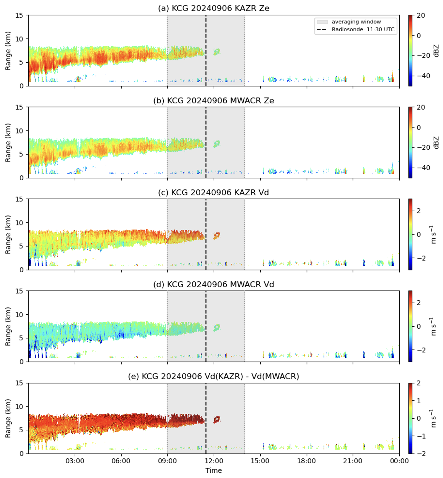
Figure 1Time–height cross sections of radar reflectivity (Ze) and Doppler velocity (Vd) observed by KAZR and MWACR at the CAPE-k site (KCG) on 6 September 2024. Panels show (a) KAZR reflectivity, (b) MWACR reflectivity, (c) KAZR Doppler velocity, (d) MWACR Doppler velocity, and (e) Doppler velocity difference Vd (KAZR)–Vd (MWACR). The collocated radiosonde launch at 11:30 UTC is denoted by a dashed line, and the shaded regions indicate the 150 min radar-averaging window.
Figure 2 illustrates the geometric relationship between measured Vd, U, particle fall velocity (Vf), and vertical air motion (W). The radar beam pointing is defined by elevation angle θ0, measured upward from the horizontal, and azimuth angle ϕ0, measured clockwise from north. W is defined as positive upward. Doppler velocity is defined as positive along the radar beam away from the radar. The radar off-vertical tilt angle is defined as 90° −θ0. The horizontal-wind direction ϕ follows the vector-direction convention and is measured clockwise from north toward the direction in which the wind flows. This differs from the conventional radiosonde or meteorological wind direction, which indicates the direction from which the wind originates. Thus, ϕ=0° represents northward flow, whereas ϕ = 180° represents southward flow. When the radar beam is vertically pointing, the measured Vd is the sum of Vf and W. When the radar beam deviates from the vertical direction, the Doppler velocities measured by the KAZR and MWACR are therefore expressed as:
In Eqs. (1)–(2), the first term is the projection of the horizontal wind onto the radar beam. The second and third terms are the respective projections of vertical air motion and downward particle fall velocity. The terms Cka and Cw represent small instrumental errors for the KAZR and MWACR, respectively.
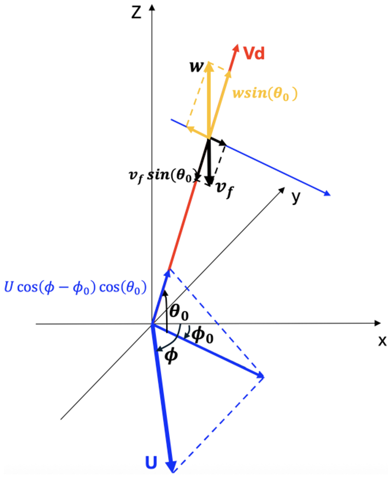
Figure 2Schematic illustration of the geometric relationship between Doppler velocity (Vd), horizontal wind (U), particle fall velocity (Vf), and vertical air motion (w). The radar beam pointing is defined by elevation angle θ0 and azimuth angle ϕ0. The horizontal wind direction is denoted by ϕ. The projection of U, Vf, and w onto the radar beam contributes to Doppler velocity when the radar beam deviates from the vertical direction.
3.1 Sensitivity of Doppler Velocity to Horizontal Wind and Beam Pointing Angle
The contribution of horizontal wind to Doppler velocity increases with both horizontal wind speed and radar beam off-zenith angle. To illustrate this sensitivity, Doppler velocity was simulated as a function of wind direction for different horizontal wind speeds and radar elevation pointing angles, assuming zero particle fall velocity and zero vertical air motion in order to isolate the contribution of horizontal wind. The azimuth angle of the radar beam is assumed to be constant at 135°.
The results are shown in Fig. 3. When the radar beam is perfectly vertical (θ0=90°), Doppler velocity shows no dependence on horizontal wind speed or wind direction because the horizontal wind vector is perpendicular to the radar beam. When the radar beam deviates slightly from vertical pointing, Doppler velocity exhibits a cosine dependence on wind direction, with maximum magnitude occurring when the horizontal wind direction is aligned with or opposite to the radar azimuth angle.
For a small pointing offset of 0.5° (θ0=89.5°), the contribution of horizontal wind produces a weak but detectable Doppler velocity signal. For example, when horizontal wind speed is 10 m s−1, the resulting maximum Doppler velocity magnitude is approximately 0.1 m s−1. For stronger winds of 40 m s−1, which are commonly observed in upper-level jet conditions, the maximum Doppler velocity contribution increases to approximately 0.3 m s−1.
As the off-zenith angle increases, the magnitude of the wind-induced Doppler velocity increases approximately proportionally to cos(θ0). Increasing the beam offset from 0.5 to 1° approximately doubles the amplitude of the wind-induced Doppler velocity signal, while increasing the offset to 2° produces an approximately fourfold increase relative to the 0.5° case. This strong sensitivity to small pointing offsets demonstrates that the wind-direction dependence of Doppler velocity provides an effective method for estimating and validating radar beam pointing.
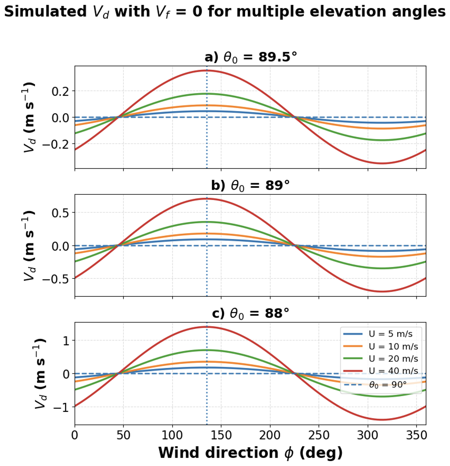
Figure 3Simulated Doppler velocity (Vd) as a function of wind direction for different horizontal wind speeds (U) and radar elevation angles (θ0), illustrating the dependence of Vd on beam mispointing, assuming zero fall velocity and air motion: (a) θ0=89.5°, (b) θ0=89°, and (c) θ0=88°.
3.2 Horizontal Wind U Normalization of Doppler Velocity Direction Display (UN-VDD)
Equations (1) and (2) and Fig. 3 show that the contribution of horizontal wind to Doppler velocity depends on both wind speed and radar beam pointing geometry. Because horizontal wind speed varies with height and time, direct comparison of Doppler velocity between radar and radiosonde measurements can be influenced by variability in wind magnitude. To isolate the geometric contribution of beam pointing to Doppler velocity, the observed Doppler velocity is normalized by horizontal wind speed obtained from radiosonde measurements.
Dividing Eq. (1) by horizontal wind speed U yields
For sufficiently strong horizontal wind speeds, the third terms in Eq. (3) become small compared to the first, wind-projection term. The second term represents the contributions of particle fall velocity and vertical air motion. Their contributions are not expected to vary systematically with wind direction; instead, they introduce scatter and an approximately direction-independent offset in the normalized Doppler velocity. This approximation is particularly appropriate for upper-level ice clouds, where particle fall velocities and vertical air motions are generally weak relative to synoptic-scale horizontal winds. Under these conditions, the normalized Doppler velocity can be approximated as
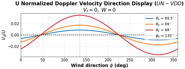
where C represents a small constant offset that accounts for the combined contribution of mean particle fall velocity, mean vertical air motion, and potential calibration bias. The amplitude of the cosine relationship is proportional to cos(θ0) and therefore increases with the off-vertical pointing angle, while its phase provides the beam-tilt azimuth ϕ0. Normalization reduces the dependence of Doppler velocity magnitude on wind speed and emphasizes its cosine dependence on wind direction. Consequently, primarily reflects the radar beam-pointing geometry rather than variations in wind magnitude. Figure 4 presents the UN-VDDs for the simulated radar pointing offsets shown in Fig. 3. As Vf and W are set to zero, the cosine relationship is centered at zero. In actual observations, particle sedimentation produces a negative bias and scatter in the fitted relationship, as demonstrated in the following section. Because particle fall velocity is related to radar reflectivity, we will evaluate the sensitivity of the retrieved beam-pointing parameters to the reflectivity threshold used for sample selection.
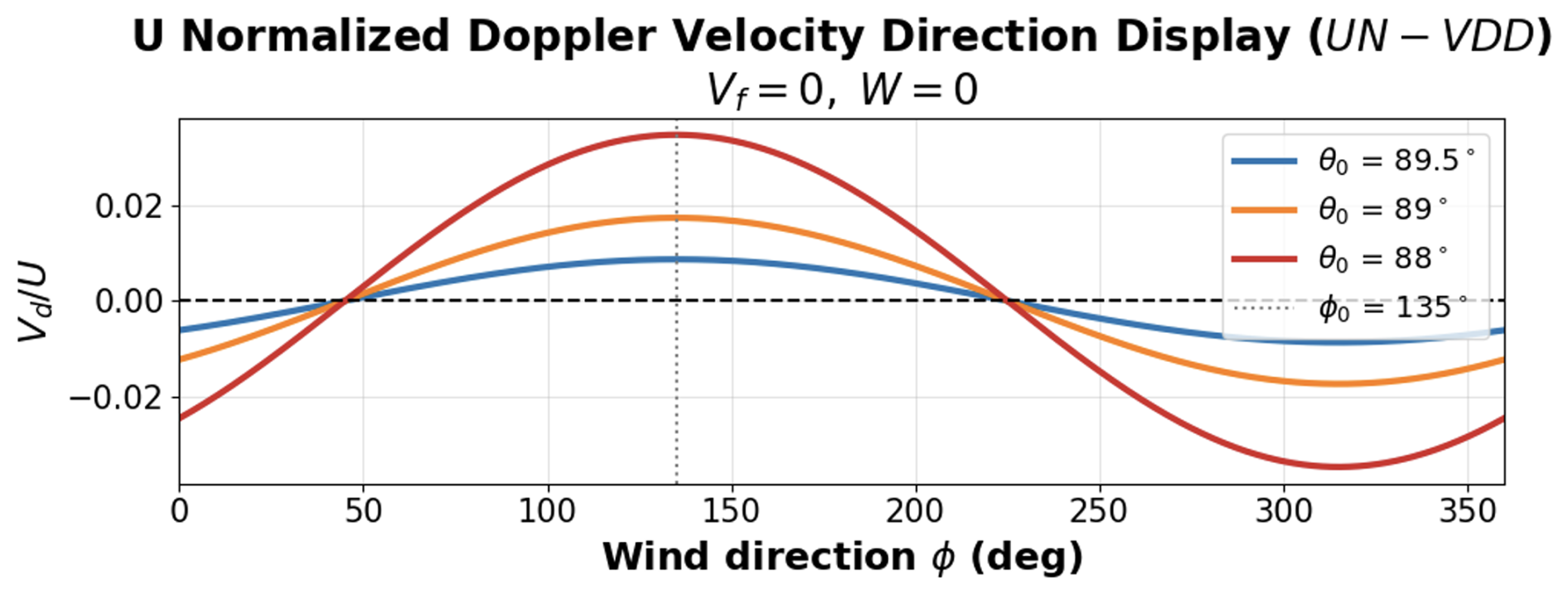
Figure 4U-normalized velocity–direction displays (UN-VDDs) derived from the simulations in Fig. 3 for θ0=89.5, 89, and 88°.
3.3 UN-VDD Beam Pointing Estimation Using Radiosonde Observations
To implement the UN-VDD for radar pointing estimation, for each radiosonde launch, radar Doppler velocity profiles (Vd) are averaged within a time window of ± 150 min centered on the radiosonde launch time. The temporal averaging reduces variability associated with turbulence and short-term cloud evolution while maintaining consistency with the large-scale wind profile measured by the radiosonde. Radiosonde temperature profiles are used to identify atmospheric layers above the melting level in order to minimize the contribution of precipitation fall velocity. The averaged Doppler velocity profiles are then interpolated to the radiosonde data grid and examined together with radiosonde wind speed and wind direction profiles. The radiosonde profiles have a median vertical spacing of approximately 10.3 m, with a 5th–95th percentile range of 8.8–13.3 m. Because the radar range-gate spacing is 30 m, approximately three radiosonde levels correspond to one radar range gate. Interpolation to the radiosonde grid facilitates collocation but does not increase the intrinsic vertical resolution of the radar observations.
Figure 5 shows an example of this processing procedure for the case in Fig. 1. In this case, the wind direction is relatively uniform between the surface and approximately 15 km altitude, with winds primarily from the northwest. Wind speed increases substantially with height, from approximately 10 m s−1 near the surface to nearly 90 m s−1 near 11 km altitude, consistent with the presence of strong upper-level flow. KAZR measures two layers of clouds, and the upper layer is our focus here. The Doppler velocity measured by KAZR exhibits a corresponding increase with height, increasing from approximately 0.5 m s−1 near 6 km to about 2 m s−1 near 8 km. In contrast, MWACR Doppler velocity exhibits weaker vertical variation, with general downward motion ranging from 0 to 0.5 m s−1.
Because the contribution of horizontal wind to Doppler velocity depends primarily on wind direction rather than altitude, observations from multiple heights within ice cloud layers can be combined to improve statistical robustness. In individual radiosonde cases, wind direction may not vary sufficiently with height to clearly reveal the cosine dependence predicted by Eq. (2). Therefore, observations from multiple radiosonde launches throughout the field campaign are combined to obtain a broad sampling of wind directions. This aggregation allows identification of the expected cosine dependence of normalized Doppler velocity on wind direction and enables estimation of radar beam pointing offsets.
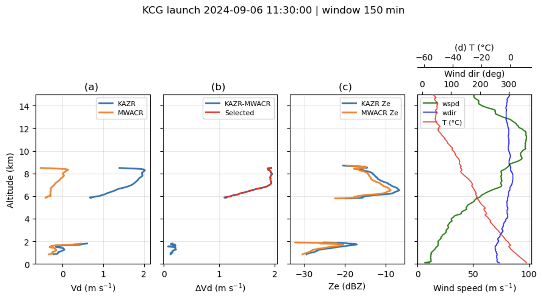
Figure 5Profiles of KCG KAZR and MWACR Doppler velocity (Vd) averaged over a time window centered on the radiosonde launch, together with collocated radiosonde profiles of temperature, wind speed, and wind direction.
4.1 KAZR Observations from CAPE-k
The CAPE-k campaign was deployed from 15 April 2024, to 15 October 2025. The radiosonde measurements in Fig. 6a show that the dominant in-cloud winds were directed toward azimuths of approximately 50–150°, measured clockwise from north, corresponding to flow toward the northeastern through eastern to south-southeastern sector. The corresponding Doppler velocity as a function of wind direction (Fig. 6b) shows a baseline Vd at approximately −0.8 m s−1, consistent with typical fall velocities of ice particles. Superimposed on this baseline Vd, a wind-direction-dependent modulation is evident, with a maximum positive Doppler velocity of 1.5 m s−1, occurring near a wind direction of 140°, approximately aligned with the radar azimuth angle. This modulation is comparable to the simulated wind-projection component shown in Fig. 3c.
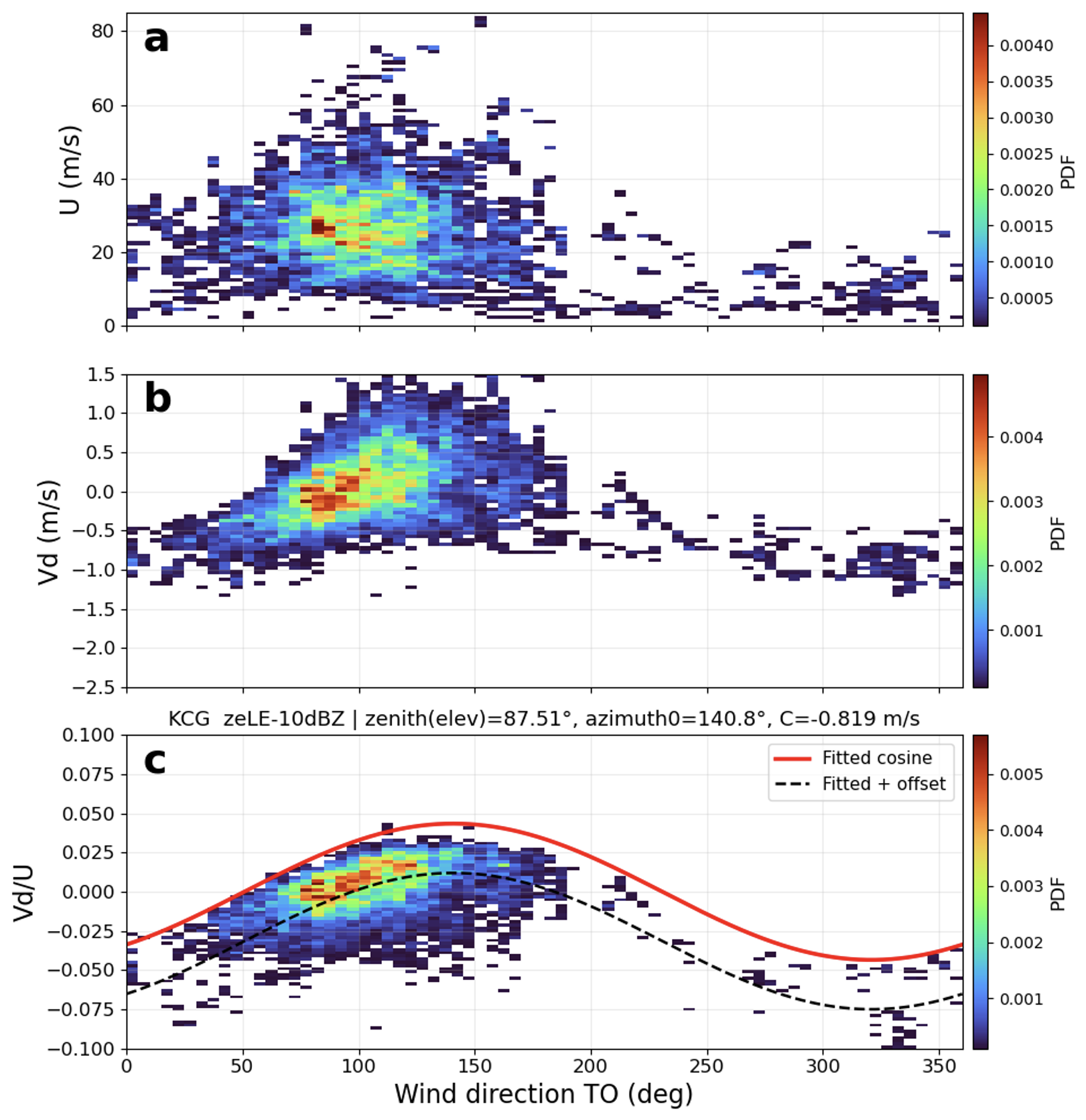
Figure 6KAZR pointing validation at CAPE-k. (a) Horizontal wind speed (U), (b) Doppler velocity (Vd), and (c) normalized Doppler velocity () as a function of wind direction defined as the direction toward which the wind flows, rather than the meteorological direction from which it originates. In panel (c), cosine fits to are shown with and without a constant offset; the offset (−0.819 m s−1) represents the combined contribution of mean particle fall velocity and vertical air motion.
Figure 6c shows the application of UN-VDD. After normalization by horizontal wind speed, the dependence of Doppler velocity on wind direction becomes more clearly defined. The normalized observations exhibit a cosine variation consistent with the cosine dependence predicted by Eq. (2). A cosine function is fitted to the observations to estimate the radar beam pointing parameters. The amplitude of the fitted cosine function corresponds to an elevation pointing angle θ0 of approximately 87.5°, a beam tilt of 2.5° from vertical. The phase shift provides an estimate of the azimuth pointing direction ϕ0 of approximately 140°, indicating the direction of beam tilt relative to geographic north.
4.2 MWACR Observations from the CAPE-k
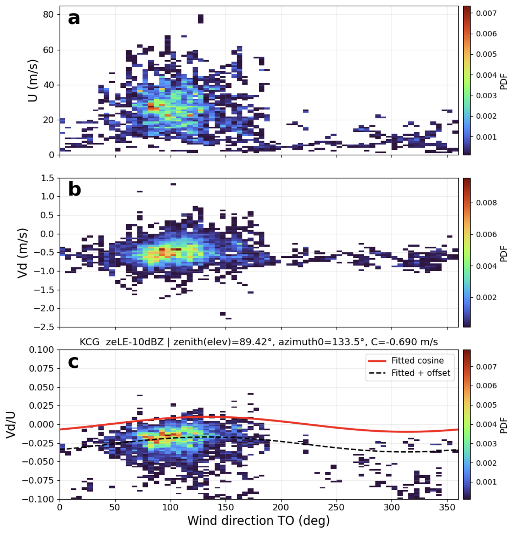
The same analysis procedure is applied to MWACR observations collected during the CAPE-k field campaign to evaluate beam pointing characteristics and provide an independent comparison with KAZR. Figure 7 summarizes the MWACR observations using data from the full campaign period. Figure 7b shows Doppler velocity as a function of wind direction. The MWACR Doppler velocity exhibits variability associated with changes in horizontal wind speed, superimposed on a mean Doppler velocity of approximately −0.7 m s−1. Compared with KAZR, the MWACR Doppler velocity shows a smaller wind-direction-dependent modulation, indicating a weaker influence of horizontal wind projection.
Figure 7c shows the corresponding UN-VDD. After normalization by horizontal wind speed, the MWACR observations exhibit a relatively weak cosine dependence on wind direction compared with KAZR. The fitted cosine function yields an elevation pointing angle of approximately 89.4°, corresponding to an off-vertical pointing of about 0.6°. The fitted azimuth angle is about 133°.
4.3 Difference Between KAZR and MWACR Doppler Velocity
To further validate the beam-pointing estimation method, the Doppler velocity difference between KAZR and MWACR is examined. Because the two radars observe nearly the same atmospheric volume, the contributions from Vf and W are expected to be similar. Taking the Doppler velocity difference therefore reduces the influence of these atmospheric contributions and emphasizes differences associated with radar beam pointing.
The Doppler velocity difference is defined as
Assuming that the contributions from particle fall velocity and vertical air motion largely cancel, the Doppler velocity difference can be approximated as
is the effective elevation angle of the relative pointing offset, and C′ is a constant offset term. After normalization by horizontal wind speed,
Figure 8 shows the Doppler velocity difference between KAZR and MWACR for all radiosonde cases during the field campaign. Panel (a) is identical to Figs. 6a and 7a. Panel (b) shows the Doppler velocity difference as a function of wind direction. The mean Δvdis close to zero, indicating that the contributions from particle fall velocity and vertical air motion largely cancel, as expected. The Doppler velocity difference exhibits a systematic wind-direction dependence, with maximum values of approximately 1–1.5 m s−1 occurring near a wind direction of about 140°.
Panel (c) shows the normalized Doppler velocity difference, , as a function of wind direction. Compared with the individual radar results, the normalized difference exhibits a clearer cosine dependence and a much smaller constant offset. The fitted cosine relationship indicates an effective elevation angle of approximately 88.5°, corresponding to a relative off-vertical pointing of about 1.5°, and an azimuth direction near 140°. The near-zero offset term indicates that differencing largely removes the mean contributions from particle fall velocity and vertical air motion that appear as offsets in the individual radar analyses.
This result provides an important validation of the method. Because the differencing approach suppresses the common atmospheric contributions to Doppler velocity, the remaining wind-direction-dependent signal more directly reflects the relative beam pointing difference between the two radars. The consistency between the individual-radar fits and the difference analysis supports the interpretation that the observed cosine dependence of Doppler velocity on wind direction primarily results from radar beam mispointing.
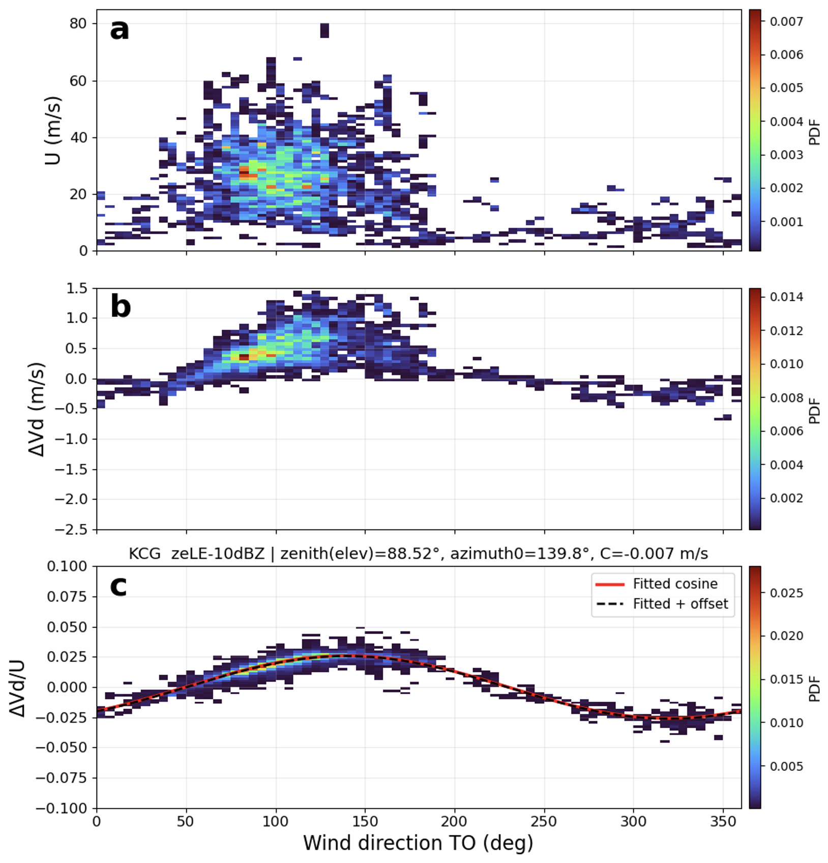
Figure 8Same as Figs. 6 and 7, but for the difference in Doppler velocity (ΔVd) between KAZR and MWACR.
4.4 Application to the recent campaigns and fixed sites
To assess whether the proposed beam-pointing validation method is applicable beyond the CAPE-k campaign, the same analysis was applied to KAZR observations collected during the Bankhead National Forest (BNF, Kuang et al., 2026) and other field campaigns. Figure 9 summarizes the KAZR observations from the BNF campaign. Panel (a) shows horizontal wind speed as a function of wind direction derived from radiosonde measurements. Similar to CAPE-k, the BNF dataset includes a broad range of wind speeds, typically between 10 and 60 m s−1, with occasional stronger winds exceeding 80 m s−1, providing sufficient variability for evaluating the wind-projection component of Doppler velocity. Panel (b) shows the corresponding KAZR Doppler velocity observations. The mean Doppler velocity is approximately −0.5 m s−1. The wind-direction-dependent variability in Doppler velocity is weaker than that observed for KAZR at CAPE-k and is comparable in magnitude to the MWACR results shown in Fig. 7. Panel (c) shows the normalized Doppler velocity, , as a function of wind direction. The normalized observations exhibit a weak but systematic cosine dependence consistent with the cosine relationship predicted for small beam pointing offsets. The cosine fit yields a retrieved elevation angle of approximately 89.5°, corresponding to an off-vertical pointing offset of about 0.5°, and an azimuth angle near 130°. Compared with the CAPE-k KAZR result, the weaker cosine signal at BNF indicates a smaller beam pointing offset during this campaign period.
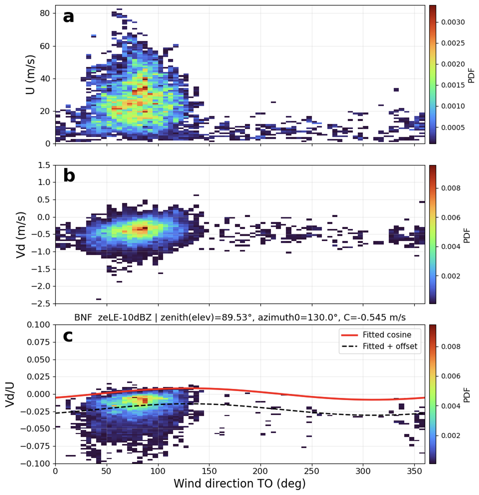
The estimated off-vertical pointing angle of about 0.5° is relatively small and is comparable to expected uncertainties associated with both instrument characteristics and the retrieval method. Several factors can contribute to this level of uncertainty. First, the effective beam direction can be influenced by the radar beam width and sidelobe structure. Even if the radar container and antenna mount are mechanically aligned with the local vertical, slight asymmetries in the antenna radiation pattern or sidelobe contamination may introduce a small effective tilt in the zenith beam. Second, partial beam filling near cloud boundaries or horizontal inhomogeneity in ice cloud layers can introduce variability in the observed Doppler velocity that is not related to beam pointing. Third, spatial separation between the radar sampling volume and radiosonde wind measurements introduces representativeness uncertainty, particularly in environments with strong wind shear or horizontal variability.
Additional uncertainty arises from methodological choices in Doppler velocity averaging and UN-VDD fitting. The averaging-window sensitivity tests quantify uncertainty associated with radar–radiosonde collocation and temporal averaging. Using windows of ± 30, ± 50, ± 90, ± 120, and ± 150 min, the retrieved elevation angle varied by less than 0.3°. The sensitivity of the retrieval to particle fall velocity was evaluated by applying reflectivity thresholds of −30, −20, −10, and 0 dBZ, thereby sampling ice-cloud layers with different particle-size and fall-speed characteristics. The fitted elevation angle varied by less than 0.25° across these thresholds. Considering both sources conservatively, the overall uncertainty in the estimated beam-pointing angle is approximately 0.5°. This value is an empirical estimate based on the sensitivity tests rather than a formal propagation of statistically independent errors.
These results indicate that the proposed method provides stable and physically consistent estimates of beam pointing across different field campaigns. The relatively small pointing offsets retrieved at BNF, together with the larger offset identified at CAPE-k, demonstrate that the method is capable of detecting both small and moderate deviations from vertical pointing while maintaining uncertainty within approximately 0.5°.
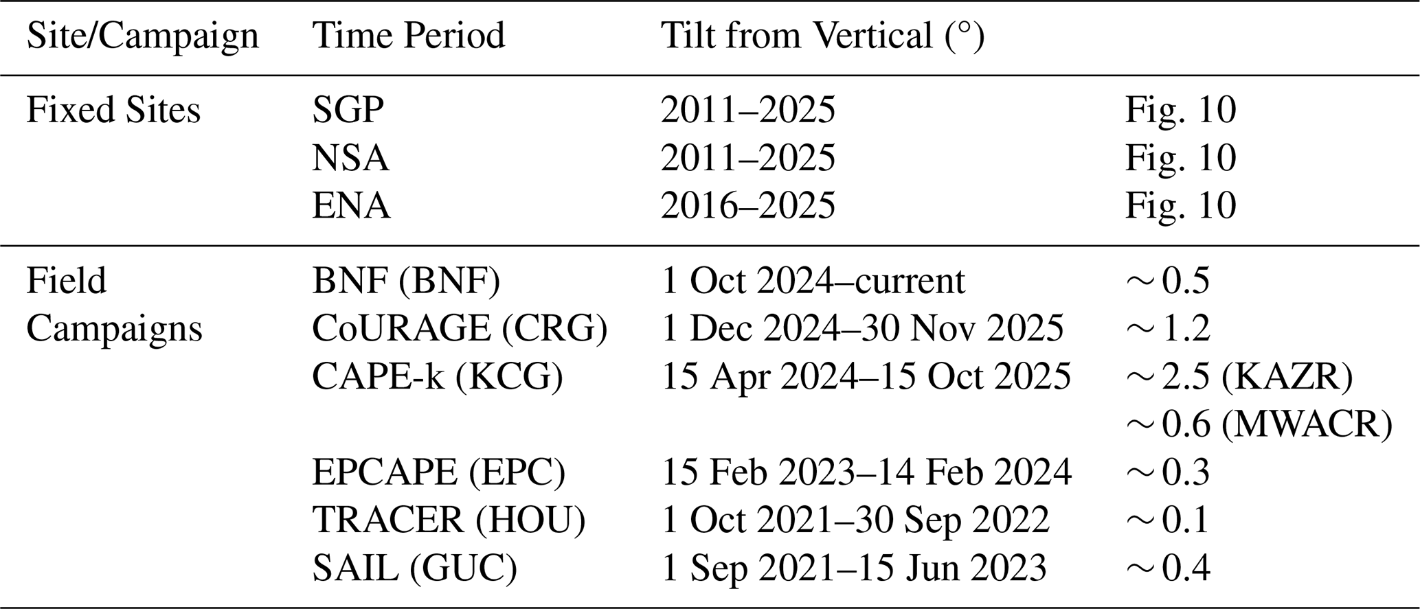
The estimated beam-pointing offsets for recent ARM field campaigns, including the Surface Atmosphere Integrated Field Laboratory (SAIL), TRacking Aerosol Convection interactions ExpeRiment (TRACER), Eastern Pacific Cloud Aerosol Precipitation Experiment (EPCAPE), Coast-Urban-Rural Atmospheric Gradient Experiment (CoURAGE), CAPE-k, and BNF, are summarized in Table 1. Long-term results for the fixed ARM sites – the Southern Great Plains (SGP), North Slope of Alaska (NSA), and Eastern North Atlantic (ENA) – from 2011–2025 are presented in Figure 10. Overall, the retrieved pointing offsets for most field deployments are within approximately 0.5°, indicating generally good mechanical alignment of the radar antenna relative to the local vertical despite challenges associated with instrument transport, installation, and variable environmental conditions encountered during field operations. Two campaigns show larger deviations: CoURAGE exhibits a moderate offset (∼ 1.2°), while CAPE-k shows the largest offset (∼ 2.5° for KAZR). These results demonstrate that most ARM field deployments maintain near-vertical pointing within the expected uncertainty range, and that the proposed method is sufficiently sensitive to identify significant alignment deviations when they occur.
Table 1Estimated KAZR and MWACR beam-pointing tilts from vertical for fixed sites and recent field campaigns.
For the long-term fixed sites, the results indicate stable pointing performance at SGP and NSA, with typical offsets near 0.5° throughout the 2011–2025 period. This consistency reflects the effectiveness of routine maintenance and periodic instrument levelling performed by ARM radar mentors. A notable deviation is observed at ENA during 2017–2018, where the retrieved pointing offset increases relative to other periods, which resulted in increased Doppler velocity, as reported in an ARM data quality report (https://adc.arm.gov/ArchiveServices/DQRService?dqrid=D190321.8, last access: 24 September 2026). ARM corrective maintenance (CM) records document a radar levelling procedure conducted in January 2019, after which the estimated pointing offset decreased to approximately 0.1°, indicating restoration of near-vertical alignment. The improved pointing stability following this maintenance activity highlights the importance of periodic mechanical verification and adjustment of radar alignment, particularly after instrument relocation, exposure to severe environmental conditions, or extended operational periods.
Together, Table 1 and Fig. 10 demonstrate that the proposed method can be applied consistently across both short-term field deployments and long-term operational sites, providing a unified and quantitative framework for evaluating radar pointing performance across the ARM KAZR network. The results also illustrate how beam pointing diagnostics can complement routine instrument maintenance records by identifying periods of potential misalignment and providing an independent observational constraint on radar mechanical stability.
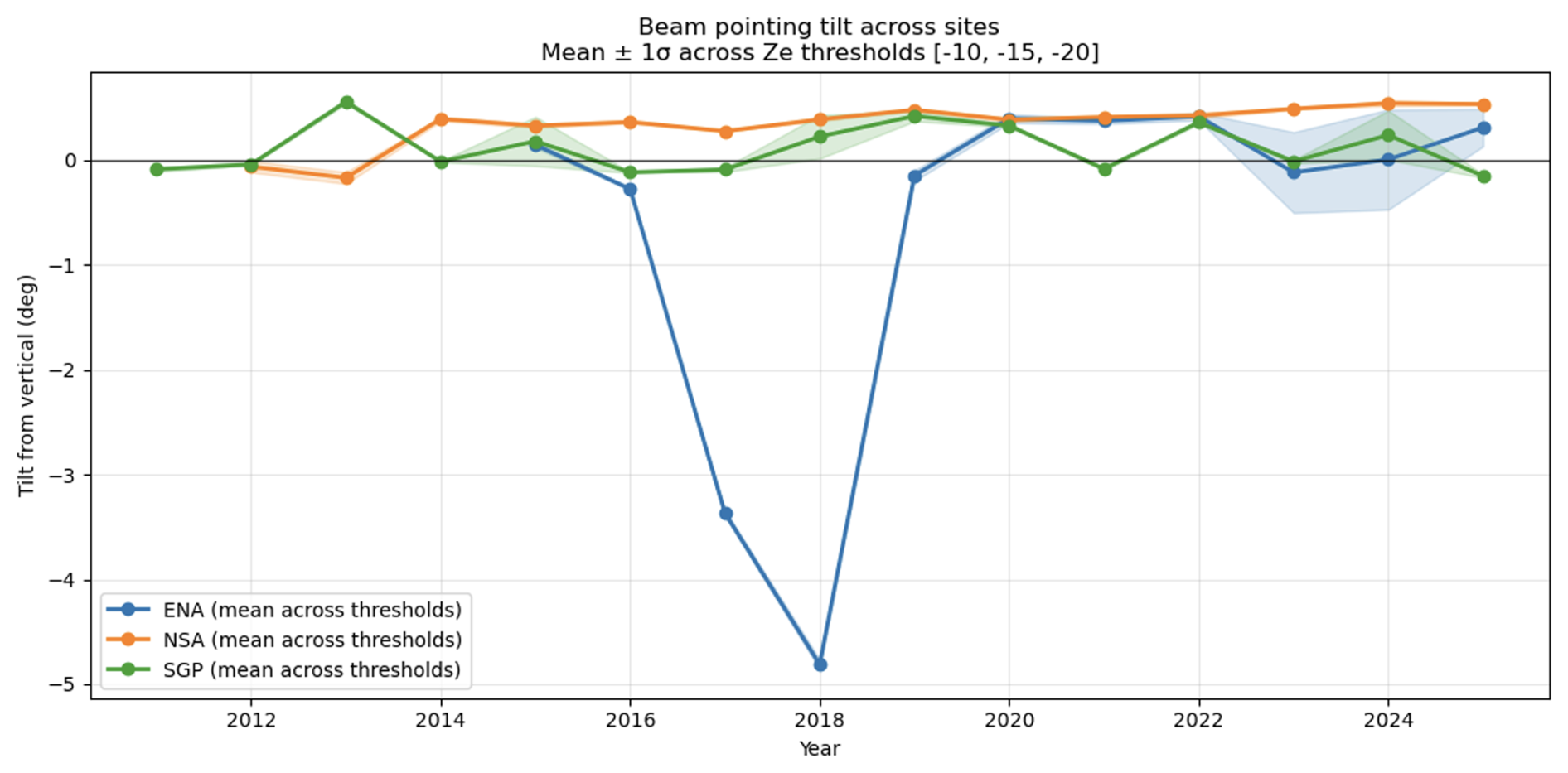
Figure 10Time series of the mean KAZR beam-pointing tilt from vertical at the ENA, NSA, and SGP sites during 2011–2025. Tilt estimates are derived using multiple radar reflectivity (Ze) thresholds (−10, −15, and −20 dBZ) to filter the observations used in the pointing estimation. Shaded regions represent the standard deviation of the tilt estimates obtained using the different Ze thresholds, indicating the sensitivity of the retrieval to reflectivity-based data selection. The results show generally stable pointing within approximately 0.5° at NSA and SGP over the analysis period, while a larger deviation is evident at ENA during 2017–2018.
Accurate beam pointing is essential for vertically pointing cloud radars because Doppler velocity measurements are widely used to infer vertical air motion and hydrometeor fall velocity. Even small deviations from vertical pointing introduce a horizontal wind contribution through geometric projection onto the radar beam, potentially biasing the interpretation of cloud dynamical and microphysical processes. This study developed and evaluated the U-normalized velocity–direction display (UN-VDD), which uses collocated radiosonde measurements to estimate the elevation and azimuth of a nominally vertically pointing radar beam. Normalizing Doppler velocity by horizontal wind speed reduces its dependence on wind magnitude and emphasizes the cosine variation with wind direction produced by beam mispointing. The amplitude and phase of the fitted cosine relationship provide estimates of the off-vertical angle and beam-tilt azimuth, respectively.
Application of UN-VDD to the CAPE-k observations identified pointing offsets in both KAZR and MWACR, with KAZR exhibiting the larger off-vertical deviation. The wind-direction dependence was clearer in the difference between the two radar Doppler velocities because differencing reduced the common contributions from particle fall velocity and vertical air motion. This result provided an independent constraint on the relative pointing difference between the two instruments. Application to BNF, other recent ARM campaigns, and long-term fixed-site observations produced generally small and stable pointing estimates, demonstrating that the method can be applied across different instruments, deployments, and atmospheric conditions.
Radiosonde measurement and sampling errors contribute to retrieval uncertainty. Wind-speed errors affect normalization by U, whereas wind-direction errors affect the independent variable in the cosine fit. These uncertainties can be propagated using weighted orthogonal-distance regression or Monte Carlo perturbations of radiosonde winds. Sensitivity tests involving radar averaging periods and reflectivity-based sampling suggest an uncertainty of approximately 0.5° in the retrieved off-vertical angle. This value should be considered an empirical estimate rather than a formal uncertainty bound unless radiosonde errors are explicitly propagated.
Radar pointing may change because of foundation settling, environmental loading, maintenance, scanner wear, or instrument relocation. A reference estimate established after installation, followed by reassessment after relocation, major maintenance, or severe environmental events, could help identify alignment changes. At sites with routine radiosonde launches, rolling UN-VDD estimates could also reveal gradual or seasonal variations.
The required sampling period should be determined by wind-direction coverage, atmospheric conditions, and retrieval uncertainty rather than by a fixed number of soundings. A small number of profiles may be sufficient when vertical wind shear provides broad directional sampling, whereas observations limited to two opposing directions constrain only one component of the tilt vector. Operational estimates should therefore include directional coverage, confidence intervals, and fit-stability metrics, with poorly constrained retrievals flagged rather than interpreted as physical pointing changes.
6.1 Doppler-velocity correction
The retrieved pointing angles can be used to remove horizontal-wind contamination from the measured Doppler velocity. Whether a correction is necessary should be determined from the expected velocity bias and the accuracy requirements of the intended radar product, rather than from a universal pointing-angle threshold. For a small off-vertical angle δ, the maximum horizontal-wind contribution is approximately Uδ, with δ expressed in radians. Thus, a 0.5° pointing offset can produce maximum Doppler-velocity biases of approximately 0.17 and 0.35 m s−1 at horizontal wind speeds of 20 and 40 m s−1, respectively. A correction is most appropriate when the pointing offset is statistically distinguishable from zero, the tilt azimuth is adequately constrained, and the projected velocity bias exceeds the uncertainty acceptable for the intended application. Pointing estimates comparable to their uncertainty should generally be monitored or flagged rather than corrected deterministically.
Using the angle convention adopted in this study and the collocated wind-field measurement, the corrected vertical Doppler velocity is calculated as:
After correction, the Doppler velocity contains the vertical contributions from particle sedimentation and air motion, along with any residual calibration error. Uncertainty in the wind field propagates directly into the corrected velocity, while spatial and temporal separation between the radar and wind measurement may introduce additional bias. Evaluation of the correction using independent wind and velocity constraints remains an important topic for future work.
Overall, UN-VDD provides a practical and independent method for estimating and monitoring the pointing of vertically oriented cloud radars using routinely available radiosonde observations. The method detects the wind-direction-dependent Doppler signature produced by small pointing offsets, supports comparisons between collocated radars, and provides the information needed to estimate and correct the associated horizontal-wind contamination. Its application across field campaigns and fixed sites demonstrates its potential as a scalable quality-control tool for improving the consistency and interpretation of ARM cloud-radar Doppler velocity and related geophysical products.
Data availability. The Ka-band ARM Zenith Radar (KAZR) and Marine W-band ARM Cloud Radar (MWACR) observations used in this study, including measurements from the CAPE-k, BNF, CoURAGE, EPCAPE, SAIL, and TRACER campaigns and the fixed ARM sites SGP, ENA, and NSA, are publicly available through the Atmospheric Radiation Measurement (ARM) Data Discovery portal. The KAZR data are available as ARM a1-level data products (Atmospheric Radiation Measurement (ARM) user facility, 2011, https://doi.org/10.5439/1984770), and the MWACR data are available from the ARM user facility (Lindenmaier et al., 2024, https://doi.org/10.5439/1973911). The radiosonde observations were obtained from the calibrated SONDEWNPN b1 datastream (Keeler et al., 2024, https://doi.org/10.5439/1595321). All datasets are publicly accessible through the ARM Data Discovery portal (https://adc.arm.gov/discovery/; last access: 24 September 2026).
MD, an ARM radar mentor and translator, led the study and the analysis and quality assessment of the ARM KAZR observations. SEG and KJ, former ARM radar translator and KAZR mentor, respectively, provided scientific guidance on radar data analysis and interpretation. IAL and TGW, ARM radar engineers, provided technical expertise on radar instrumentation and operations. AKT, JC, MR, ZZ, and AM contributed discussions and guidance regarding ARM radar operations, data analysis, and quality control. All authors reviewed and contributed to the manuscript.
The contact author has declared that none of the authors has any competing interests.
Publisher's note: Copernicus Publications remains neutral with regard to jurisdictional claims made in the text, published maps, institutional affiliations, or any other geographical representation in this paper. The authors bear the ultimate responsibility for providing appropriate place names. Views expressed in the text are those of the authors and do not necessarily reflect the views of the publisher.
Contributions from Brookhaven National Laboratory co-authors were supported by the Atmospheric Radiation Measurement (ARM) Facility and the Atmospheric System Research (ASR) program of the Office of Biological and Environmental Research in the U.S. Department of Energy, Office of Science, through Contract No. DE-SC0012704. Pacific Northwest National Laboratory (PNNL) is operated by Battelle for the U.S. Department of Energy. The authors from PNNL are also supported by ARM through Contract No. DE-SC0015990.
This research has been supported by the U.S. Department of Energy, Office of Environment, Health, Safety and Security (grant nos. DE-SC0012704 and DE-SC0015990).
This paper was edited by Haoran Li and reviewed by two anonymous referees.
Atmospheric Radiation Measurement (ARM) user facility: Ka ARM Zenith Radar (KAZR), Atmospheric Radiation Measurement (ARM) user facility [data set], https://doi.org/10.5439/1984770, 2011.
Battaglia, A. and Kollias, P.: Using ice clouds for mitigating the EarthCARE Doppler radar mispointing, IEEE Trans. Geosci. Remote Sens., 53, 2079–2085, https://doi.org/10.1109/TGRS.2014.2353219, 2015.
Browning, K. A. and Wexler, R.: The determination of kinematic properties of a wind field using Doppler radar, J. Appl. Meteor., 7, 105–113, https://doi.org/10.1175/1520-0450(1968)007<0105:TDOKPO>2.0.CO;2, 1968.
Deng, M. and Mace, G. G.: Cirrus microphysical properties and air motion statistics using cloud radar Doppler moments. Part I: Algorithm description, J. Appl. Meteor. Climatol., 45, 1690–1709, https://doi.org/10.1175/JAM2433.1, 2006.
Deng, M. and Mace, G. G.: Cirrus cloud microphysical properties and air motion statistics using cloud radar Doppler moments: Water content, particle size, and sedimentation relationships, Geophys. Res. Lett., 35, L17808, https://doi.org/10.1029/2008GL035054, 2008a.
Deng, M. and Mace, G. G.: Cirrus microphysical properties and air motion statistics using cloud radar Doppler moments. Part II: Climatology, J. Appl. Meteor. Climatol., 47, 3221–3235, https://doi.org/10.1175/2008JAMC1949.1, 2008b.
Dirksen, R. J., Sommer, M., Immler, F. J., Hurst, D. F., Kivi, R., and Vömel, H.: Reference quality upper-air measurements: GRUAN data processing for the Vaisala RS92 radiosonde, Atmos. Meas. Tech., 7, 4463–4490, https://doi.org/10.5194/amt-7-4463-2014, 2014.
Doviak, R. J. and Zrnić, D. S.: Doppler Radar and Weather Observations, 2nd edn., Academic Press, San Diego, CA, USA, 562 pp., https://doi.org/10.1016/C2009-0-22358-0, 1993.
Giangrande, S. E., Luke, E. P., and Kollias, P.: Automated retrievals of precipitation parameters using non-Rayleigh scattering at 95 GHz, J. Atmos. Oceanic Technol., 27, 1490–1503, https://doi.org/10.1175/2010JTECHA1343.1, 2010.
Giangrande, S. E., Luke, E. P., and Kollias, P.: Characterization of vertical velocity and drop size distribution parameters in widespread precipitation at ARM facilities, J. Appl. Meteor. Climatol., 51, 380–391, https://doi.org/10.1175/JAMC-D-10-05000.1, 2012.
Haimov, S. and Rodi, A.: Fixed-antenna pointing-angle calibration of airborne Doppler cloud radar, J. Atmos. Oceanic Technol., 30, 2320–2335, https://doi.org/10.1175/JTECH-D-12-00262.1, 2013.
Kalesse, H. and Kollias, P.: Climatology of high cloud dynamics using profiling ARM Doppler radar observations, J. Climate, 26, 6340–6359, https://doi.org/10.1175/JCLI-D-12-00695.1, 2013.
Keeler, E.: Balloon-Borne Sounding System (SONDE) Instrument Handbook, U.S. Department of Energy Atmospheric Radiation Measurement user facility, Richland, WA, USA, DOE/SC-ARM-TR-029, https://doi.org/10.2172/1020712, 2025.
Keeler, E., Burk, K., and Kyrouac, J.: Balloon-Borne Sounding System (SONDEWNPN), Atmospheric Radiation Measurement (ARM) user facility [data set], https://doi.org/10.5439/1595321, 2024.
Kollias, P., Albrecht, B. A., and Marks, F.: Why Mie? Accurate observations of vertical air velocities and raindrops using a cloud radar, Bull. Amer. Meteor. Soc., 83, 1471–1483, https://doi.org/10.1175/BAMS-83-10-1471, 2002.
Kollias, P., Clothiaux, E. E., Albrecht, B. A., Miller, M. A., Moran, K. P., and Johnson, K. L.: The Atmospheric Radiation Measurement Program cloud profiling radars: Second-generation sampling strategies, processing, and cloud data products, J. Atmos. Oceanic Technol., 24, 1199–1214, https://doi.org/10.1175/JTECH2033.1, 2007a.
Kollias, P., Clothiaux, E. E., Miller, M. A., Albrecht, B. A., Stephens, G. L., and Ackerman, T. P.: Millimeter-wavelength radars: New frontier in atmospheric cloud and precipitation research, Bull. Amer. Meteor. Soc., 88, 1608–1624, https://doi.org/10.1175/BAMS-88-10-1608, 2007b.
Kollias, P., Bharadwaj, N., Widener, K., Jo, I., and Johnson, K.: Scanning ARM cloud radars. Part I: Operational sampling strategies, J. Atmos. Oceanic Technol., 31, 569–582, https://doi.org/10.1175/JTECH-D-13-00044.1, 2014.
Kollias, P., Clothiaux, E. E., Ackerman, T. P., Albrecht, B. A., Bharadwaj, N., Mead, J. B., Miller, M. A., Verlinde, J., Marchand, R. T., and Mace, G. G.: Development and applications of ARM millimeter-wavelength cloud radars, Meteor. Monogr., 57, 17.1–17.19, https://doi.org/10.1175/AMSMONOGRAPHS-D-15-0037.1, 2016.
Kuang, C., Giangrande, S. E., Serbin, S. P., Campbell, P., Elsaesser, G. S., Gentine, P., Heus, T., Hickmon, N. L., Oue, M., Peters, J. M., Raghunathan, G. N., Ritsche, M. T., Smith, J. N., Spychala, M., Steiner, A. L., and Theisen, A.: The U.S. DOE ARM User Facility establishes a new site for studies of land–aerosol–cloud interactions in the southeastern United States, Bull. Amer. Meteor. Soc., 107, E1–E8, https://doi.org/10.1175/BAMS-D-25-0072.1, 2026.
Lhermitte, R. M.: Cloud and precipitation remote sensing at 94 GHz, IEEE Trans. Geosci. Remote Sens., 26, 207–216, https://doi.org/10.1109/36.3024, 1988.
Lindenmaier, I., Feng, Y.-C., Bharadwaj, N., Johnson, K., Isom, B., Hardin, J., Matthews, A., Wendler, T., Melo de Castro, V., and Rocque, M.: Marine W-Band (95 GHz) ARM Cloud Radar (MWACR), Atmospheric Radiation Measurement (ARM) user facility [data set], https://doi.org/10.5439/1973911, 2024.
Mather, J. H. and Voyles, J. W.: The ARM Climate Research Facility: A review of structure and capabilities, Bull. Amer. Meteor. Soc., 94, 377–392, https://doi.org/10.1175/BAMS-D-11-00218.1, 2013.
May, P. T. and Rajopadhyaya, D. K.: Vertical velocity characteristics of deep convection over Darwin, Australia, Mon. Weather Rev., 127, 1056–1071, https://doi.org/10.1175/1520-0493(1999)127<1056:VVCODC>2.0.CO;2, 1999.
Mitchell, D. L., Mishra, S., and Lawson, R. P.: Representing the ice fall speed in climate models: Results from Tropical Composition, Cloud and Climate Coupling (TC4) and the Indirect and Semi-Direct Aerosol Campaign (ISDAC), J. Geophys. Res.-Atmos., 116, D00T03, https://doi.org/10.1029/2010JD015433, 2011.
Moran, K. P., Martner, B. E., Post, M. J., Kropfli, R. A., Welsh, D. C., and Widener, K. B.: An unattended cloud-profiling radar for use in climate research, Bull. Amer. Meteor. Soc., 79, 443–455, https://doi.org/10.1175/1520-0477(1998)079<0443:AUCPRF>2.0.CO;2, 1998.
Nash, J., Oakley, T., Vömel, H., and Wei, L.: WMO Intercomparison of High Quality Radiosonde Systems, Yangjiang, China, 12 July–3 August 2010, Instruments and Observing Methods Report No. 107, WMO/TD-No. 1580, World Meteorological Organization, Geneva, Switzerland, 249 pp., https://library.wmo.int/idurl/4/50499 (last access: 14 August 2026), 2011.
Protat, A. and Williams, C. R.: The accuracy of radar estimates of ice terminal fall speed from vertically pointing Doppler radar measurements, J. Appl. Meteor. Climatol., 50, 2120–2138, https://doi.org/10.1175/JAMC-D-10-05031.1, 2011.
Seidel, D. J., Sun, B., Pettey, M., and Reale, A.: Global radiosonde balloon drift statistics, J. Geophys. Res.-Atmos., 116, D07102, https://doi.org/10.1029/2010JD014891, 2011.
Shupe, M. D., Kollias, P., Poellot, M., and Eloranta, E.: On deriving vertical air motions from cloud radar Doppler spectra, J. Atmos. Oceanic Technol., 25, 547–557, https://doi.org/10.1175/2007JTECHA1007.1, 2008.
Shupe, M. D., Comstock, J. M., Turner, D. D., and Mace, G. G.: Cloud property retrievals in the ARM Program, Meteor. Monogr., 57, 19.1–19.20, https://doi.org/10.1175/AMSMONOGRAPHS-D-15-0030.1, 2016.
Zhu, Z., Kollias, P., Yang, F., and Luke, E.: On the estimation of in-cloud vertical air motion using radar Doppler spectra, Geophys. Res. Lett., 48, e2020GL090682, https://doi.org/10.1029/2020GL090682, 2021.