the Creative Commons Attribution 4.0 License.
the Creative Commons Attribution 4.0 License.
 | 12 Sep 2019
Calibration of the 2007–2017 record of Atmospheric Radiation Measurements cloud radar observations using CloudSat
Pavlos Kollias
Bernat Puigdomènech Treserras
Alain Protat
The U.S. Department of Energy (DOE) Atmospheric Radiation Measurements (ARM) facility has been at the forefront of millimeter-wavelength radar development and operations since the late 1990s. The operational performance of the ARM cloud radar network is very high; however, the calibration of the historical record is not well established. Here, a well-characterized spaceborne 94 GHz cloud profiling radar (CloudSat) is used to characterize the calibration of the ARM cloud radars. The calibration extends from 2007 to 2017 and includes both fixed and mobile deployments. Collectively, over 43 years of ARM profiling cloud radar observations are compared to CloudSat and the calibration offsets are reported as a function of time using a sliding window of 6 months. The study also provides the calibration offsets for each operating mode of the ARM cloud radars. Overall, significant calibration offsets are found that exceed the uncertainty of the technique (1–2 dB). The findings of this study are critical to past, ongoing, and planned studies of cloud and precipitation and should assist the DOE ARM to build a legacy decadal ground-based cloud radar dataset for global climate model validation.
- Article
(5532 KB) - Full-text XML
- BibTeX
- EndNote


The first millimeter-wavelength cloud radars (MMCRs; Moran et al., 1998) of the U.S. Department of Energy Atmospheric Radiation Measurement (ARM) facility were installed at the Tropical Western Pacific (TWP), Manus, and Southern Great Plains (SGP) sites in 1996. Since then, the ARM facility has been at the forefront of short-wavelength radar development and operations for over 2 decades (Kollias et al., 2016). In the beginning, emphasis was placed on demonstrating high operational stability and developing standard hydrometeor location and spectral products (Clothiaux et al., 2001; Kollias et al., 2007b). The ARM facility MMCR calibration efforts were limited to subcomponent characterization (i.e., antenna gain), monitoring of the transmitted peak power, and infrequent detailed characterization of the radar receiver by injecting signal with known amplitude. In 2005, the ARM facility started the deployment of its mobile facilities and the gradual modernization of the MMCR receiver. This led to the development of the W-band ARM Cloud Radar (WACR). In 2009, the ARM facility embarked on a significant expansion of its radar facilities (Mather and Voyles, 2013). The expansion included the addition of scanning millimeter- and centimeter-wavelength radars with Doppler and polarimetric capabilities (Kollias et al., 2014a; North et al., 2017) and the development of the next-generation profiling cloud radar, the Ka-band ARM Zenith Radar (KAZR) and its upgraded second generation (KAZR2).
Part of the motivation for the ARM radar expansion was to improve cloud microphysical retrievals through the use of dual-wavelength ratios, that is, making use of the relative difference in radar scattering at different wavelengths. This difference signal is often only a few decibels and as one might expect, this requirement brought the characterization of the ARM radar calibration into focus. Early comparisons between collocated profiling ARM cloud radar indicated differences in reported radar reflectivity profiles. This hardly came as a surprise to those involved in radar characterization (Atlas, 2002). Soon after the National Aeronautics and Space Administration (NASA) Tropical Rainfall Measuring Mission (TRMM) spaceborne radar was in orbit, its remarkable stability made it a calibration standard and its comparison to the ground-based observations of the Weather Surveillance Radar-1998 Doppler (WSR-88D) network uncovered several issues with the calibration of the radars despite the mandate of the WSR-88D network on quantitative precipitation estimation and the implementation of routine calibration procedures (Bolen and Chandrasekar, 2000). On the other hand, establishing routine calibration procedures based on engineering measurements or natural targets for the ARM profiling cloud radars is a far more challenging task. The systems are only vertically pointing, thus making the use of corner reflectors or metal spheres difficult; are designed with sensitive receivers that can detect very low radar reflectivity targets but saturate in rain, thus making the use of disdrometers challenging (Gage et al., 2000); and operate in climate regimes that often have no or little precipitation and suffer from considerable gaseous and hydrometeor attenuation (Kollias et al., 2005, 2007a). Furthermore, the four different profiling cloud radars (MMCR, WACR, KAZR, and KAZR2) were deployed in different climatological regimes, for small periods of time (9–24 months mobile deployments) and often with no gaps between deployments, thus making it even more challenging to develop calibration standards. At present, the ARM facility employs a larger radar operation and engineering group and has set procedures for characterizing the ARM radars using a combination of subsystem calibrations, corner reflectors, and natural targets. However, these methods are still not fully operational today and certainly not applicable to the historic ARM profiling cloud radar dataset that spans over 2 decades.
Luckily, NASA's CloudSat mission, a 94 GHz spaceborne cloud profiling radar (CPR) was launched in April 2006 (Tanelli et al., 2008) on a circular sun-synchronous polar orbit providing coverage from 82∘ S to 82∘ N and is still operational today. In 2021, another 94 GHz spaceborne CPR with Doppler capability will be launched as part of the Earth Clouds, Aerosols and Radiation Explorer (EarthCARE) satellite, a joint European Space Agency and Japanese Aerospace Exploration Agency mission (Illingworth et al., 2015; Kollias et al., 2014b). Over the 12-year mission of CloudSat, end-to-end system calibration is performed using measured backscatter off the ocean surface, and the calibration of the CloudSat reflectivity measurements is accurate within 0.5–1 dB (Li et al., 2005; Tanelli et al., 2008). The CPR calibration quality and stability was exploited by Protat et al. (2011), who first demonstrated that using a statistical approach, CloudSat could be used as a global radar calibrator for ground-based profiling cloud radars. In the Protat et al. (2011) study, two ground-based radars, the MMCR at the North Slope of Alaska (NSA) Barrow ARM site and another 35 GHz radar system at Cabauw, the Netherlands, were calibrated using CloudSat over a short period of time (6–12 months).
In Sect. 2, the ARM facility cloud radars are presented and the Protat et al. (2011) methodology is revised and improved. Section 3 presents the results from the application of the calibration procedure to almost the entire record of ARM profiling cloud radar observations at the fixed and mobile sites from 2007 to the end of 2017 (a total of 43.5 years of radar observations). Finally, Sect. 4 presents a summary of our findings and their implications. The application of the technique to such a diverse set of radar systems and locations is expected to demonstrate the applicability of this approach to existing profiling radar networks such as the ARM facility and the future European research infrastructure network for the observations of Aerosol, Clouds and Trace gases (ACTRIS).
Here, the ARM and CloudSat CPR measurements and the methodology used for the comparison between the ground-based and space-based observations are described.
2.1 ARM cloud radar measurements
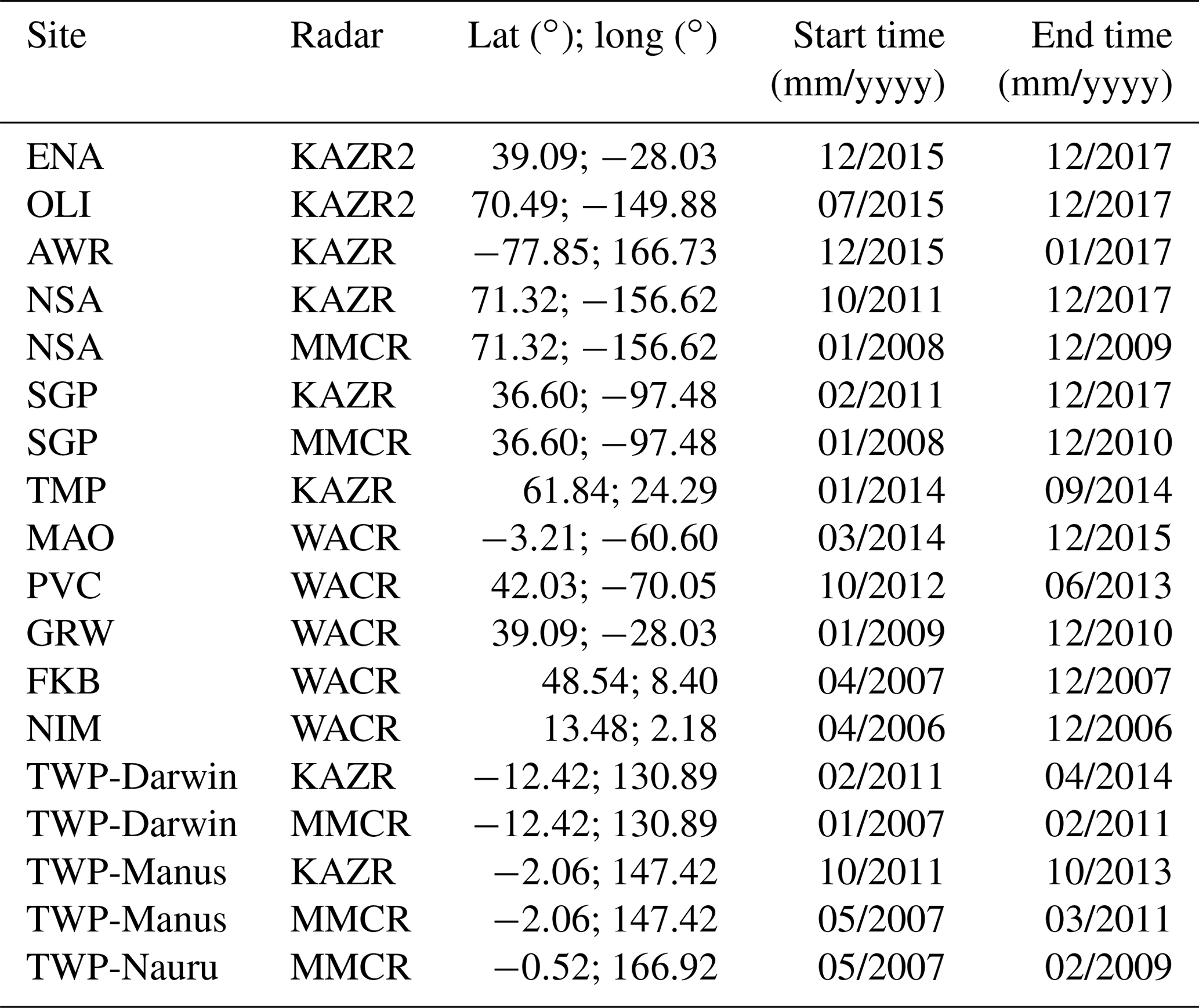
The record of ARM profiling radar observations compared to CloudSat is detailed in Table 1. In total, ARM cloud radar observations from 14 different locations (Fig. 1) with four different radar systems (MMCR, WACR, KAZR, KAZR2) for a total of 43 years and 8 months are analyzed. At a couple of sites, the calibration record starts as early as the launch of CloudSat (mid-2006) and at several sites stops at the end of 2017. For much of the record analyzed here, the WACR was the primary profiling cloud radar of the first ARM Mobile Facility (AMF) and as such has been deployed in different climatological locations. A marine version of the WACR (M-WACR) with smaller antenna and a ship-motion stabilizer has been the primary radar for marine deployments of the second AMF (AMF2). The WACR does not use pulse compression and operates only in co-polarization and cross-polarization modes. The single operating mode of the WACR combined with the fact that it uses the same frequency as the CloudSat CPR makes their comparison relatively straightforward. The MMCR used a complicated operating mode sequence (Moran et al., 1998; Kollias et al., 2007b) in order to meet the requirement of detecting all radiatively important clouds with radar reflectivity above −50 dBZ throughout the troposphere. The mode sequence includes a long pulse compression mode for detecting high level clouds (hereafter mode 2), a very short pulse for boundary layer clouds detection, a nominal length general mode that covers the whole troposphere (hereafter mode 3), and a precipitation mode that provides additional receiver protection to avoid signal saturation. These modes operated in an interleaved sequence. The KAZR system provides the chirp (hereafter mode MD) and general mode (hereafter mode GE) at the same time using a dual radar receiver channel with enough frequency separation to enable detection of two pulses transmitted at the same trigger. Finally, the KAZR2 is an improved hardware version of the KAZR, which maintains the same operating modes as the KAZR but also introduces a precipitation mode that transmits a reduced amplitude pulse to avoid receiver saturation by strong precipitation returns. The use of different operating modes comes at the expense of frequent range side lobe artifacts from high-reflectivity targets from the use of pulse compression and possible differences in the reported radar reflectivity from the different modes. The latter is commonly observed in radar systems that operate with different modes.
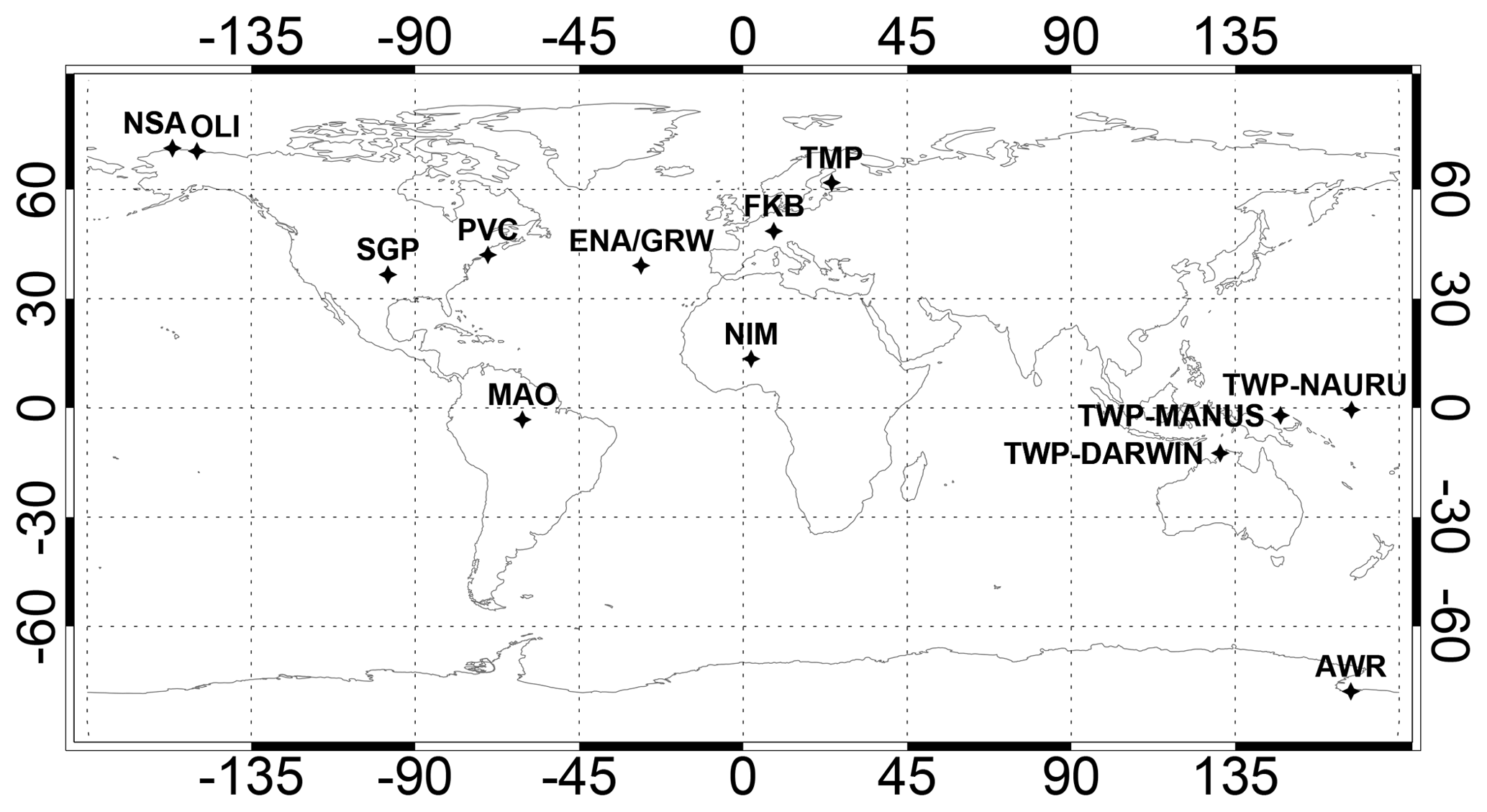
Figure 1Location of the fixed and mobile ARM profiling cloud radars calibrated using the CloudSat Cloud Profiling Radar.
Table 1Information on the sites (name and location), the type of radar, and the start and end dates of the calibration period.
Therefore, as a prelude to comparing CloudSat and ARM, we begin with a comparison of reflectivity values between ARM radar modes. As will become clear later, changes in the intramode reflectivity differences are often, though not always, indicative of changes in overall calibration. A detailed comparison between the reported radar reflectivities from all the radar systems with more than one operating mode was conducted (Fig. 2). The difference between mode 3 and mode 2 is reported for the MMCR systems and the difference between the GE and MD modes is reported for the KAZR and KAZR2 systems. The difference (dB) in the measured radar reflectivity between two modes is estimated at heights where both modes provide observations (e.g., the MMCR mode 2 does not provide data below 3.6 km) with high signal-to-noise ratio (SNR > 0 dB), and at ranges where the averaged profiles were correlated to filter our ranges where big discrepancies due to radar artifacts were present. At each height, the average reflectivity profile of each mode (in linear units) is computed using a 1-month running window. The mean of the differences in the averaged radar reflectivity profiles between the two modes is computed and shown as a function time in Fig. 2. Overall, the mode reflectivity differences are small (±2 dB) and only occasionally are the differences much higher than 2 dB. While the absolute values of mode difference in the next generation of ARM cloud profiling radars (KAZR and KAZR2) are often similar, there are arguably fewer jumps or rapid changes. In general, it is difficult to identify which mode has a better calibration because as will be shown the calibration difference between CloudSat and ARM is typically larger than ±2 dB.
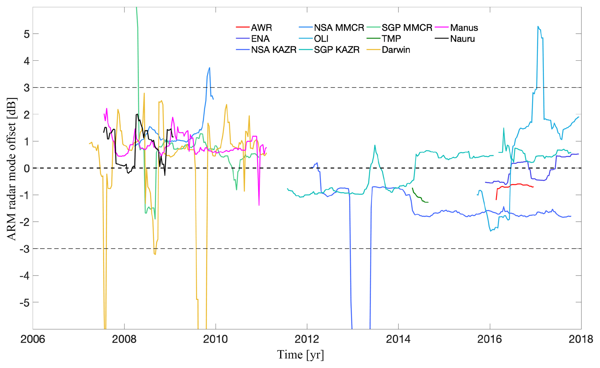
Figure 2The difference (dB) in the radar reflectivity reported between different ARM modes. For KAZR/KAZR2 systems the GE–MD difference and for MMCR systems the mode 3–mode 2 differences are reported.
2.2 The ARM–CloudSat comparison methodology
The comparisons between the ARM radars (MMCR, KAZR, and KAZR2) and the CloudSat CPR are performed independently for two modes for the MMCR (2 and 3) and two modes for the KAZR and KAZR2 (MD and GE). The approach is similar to that described in Protat et al. (2011). The technique consists in a statistical comparison of the mean vertical profiles of non-precipitating ice cloud radar reflectivities from the ground-based and spaceborne radar observations. One of the improvements introduced in this study is that the averaging of the radar reflectivity value at each height is performed in linear space (Z) and not decibels relative to Z as in Protat et al. (2011). These averaged profiles use data extracted from CloudSat overpasses in a radius of 200 km around the ARM site and ±1 h time lag around the overpass time for the ground-based radars. Another improvement introduced in this study is a rigorous selection of the CloudSat overpasses within a certain radius to avoid any errors in the estimation of the proximity of CloudSat columns to the ARM site location. Finally, the methodology investigates the difference between the ARM and CloudSat profiles in a large range of calibration offsets from −15 to +15 dB with a fine spacing of 0.1 dB rather than using an iterative process as in Protat et al. (2011). The radar reflectivity difference between the ARM and CloudSat profiles is evaluated only at the range of heights where enough samples from both sensors are available.
Several factors need to be taken into account to achieve an objective statistical comparison between ground-based and space-based observations: frequency of each radar, sensitivity, viewing geometry, attenuation correction, etc. The approximations to deal with all these factors introduce errors that are difficult to assess. The necessary steps required to find the calibration offset for each radar are described here, following the algorithm flow outlined in Fig. 3.
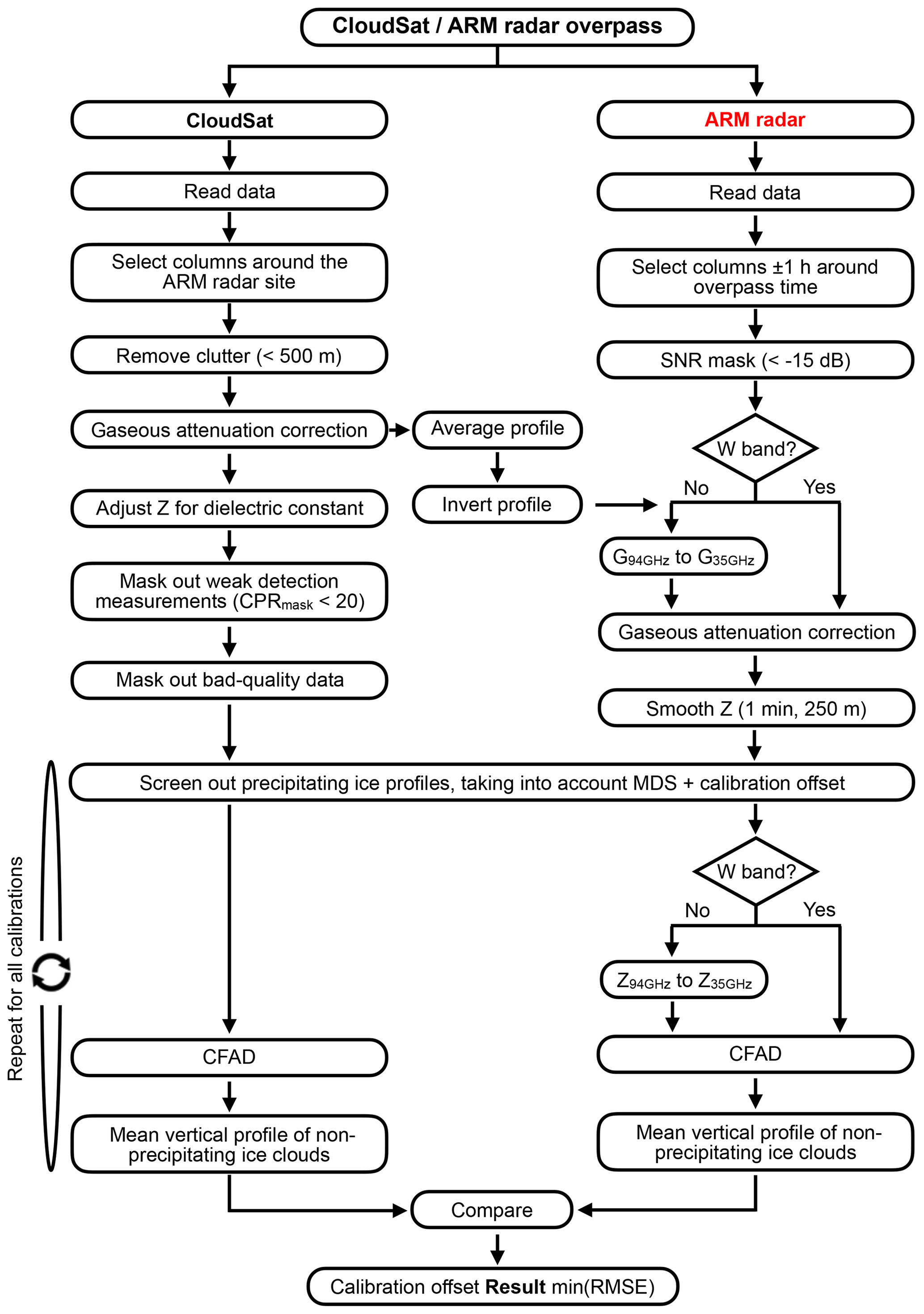
Figure 3Algorithm flowchart of the calibration of the ARM cloud radars using CloudSat observations.
The CloudSat overpasses are predicted using the two-line element (TLE) set files that encode all necessary information to define the latitude and longitude of the satellite over the Earth's surface at any given time. Using these files, the satellite position is computed with high resolution in time and the distances to each ARM radar location are used to define the overpass. Only CloudSat data passing in a radius between 100 and 300 km around the ARM radar location are extracted. Knowing the orbits of the overpasses, the CloudSat respective files are read. In this present study, the data from the fourth and fifth releases (R04 and R05) of the 2B-GEOPROF product are used to extract the CPR reflectivity, height, DEM elevation, CPR cloud mask, gaseous attenuation, and data quality flags. In addition, the height of the freezing level is extracted from the 2C-PRECIP-COLUMN product. Figure 4a shows the probability density function (pdf) of the freezing level height at the North Slope of Alaska (NSA).

Figure 4Example of the CloudSat–ARM radar calibration at the NSA for mode 2 of the MMCR for the period January 2008 to December 2009. (a) the seasonal distribution of the melting layer heights, (b) the distribution with height of the ARM radar reflectivities, (c) the distribution with height of the CloudSat radar reflectivities, (d) the comparison of the CloudSat (black) and ARM (red) cloud top height histograms. The solid red line indicates the cloud top height distribution from the archived ARM radar data and the dashed red line indicates the cloud top height distribution after 6.2 dB is subtracted by the ARM radar reflectivities, (e) the comparison of the CloudSat (black) and ARM (red) mean radar reflectivity profiles. The solid red line indicates the ARM mean radar reflectivity profile using the archived ARM radar data and the dashed red line indicates the ARM radar reflectivity profile after 6.2 dB is subtracted by the ARM radar reflectivities, (f) the RMSE value between the radar reflectivity profiles for different calibration offsets.
All CPR observations within 500 m from Earth's surface are removed to avoid residual surface clutter contaminations. In addition, all CPR detections at very low signal-to-noise ratio (SNR) conditions (CPR cloud mask < 20) and poor data quality points (data quality ≠ 0) are removed.
The gaseous attenuation correction reported in the CloudSat files is added to the reflectivity profile. The CPR reflectivity is normalized for the differences in the values used for the dielectric constant (K) using Eq. (1). CloudSat uses a value of 0.75 and the ARM facility uses a value of 0.99 for MMCR, 0.84 for WACR, and 0.88 for KAZR.
For the ARM radar data processing, only data with ±1 h time lag around the exact overpass time are used. All radar reflectivity values measured at SNR < −15 dB conditions are removed. The ARM radar reflectivities are corrected for gaseous attenuation using the top-down gaseous attenuation profile (G94 GHz) available in the CloudSat data products. The G94 GHz estimates in the operational CloudSat products are based on Liebe (1989). First, the profile is inverted to represent the gaseous attenuation for a ground-based system. If the ground-based system is the WACR (same frequency with CloudSat), no further conversion is needed and the is used to correct the WACR radar reflectivities. If the ground-based system is a 35 GHz radar (MMCR, KAZR, KAZR2), then a conversion factor C is used to convert the to 35 GHz gaseous attenuation (G35 GHz) using Eq. (2).
The conversion factor is derived from Rosenkranz (1998) and a large number of ARM soundings, and its average value depends on the ARM radar location (i.e., 1.45±0.5 for AWR, 2.08±0.5 for NSA, Oliktok Point (OLI) and Hyytiälä, Finland (TMP), 3.36±0.5 for Eastern North Atlantic (ENA) and SGP, and 4.03±0.5 for TWP). Considering that the averaged integrated two-way attenuation at 35 GHz at these locations is 0.4 dB for AWR, NSA, OLI, and TMP; 0.6 dB for ENA and SGP; and 1.0 for TWP, the uncertainty introduced by using the conversion factor is 0.13 dB at AWR; 0.09 dB at NSA, OLI, and TMP; 0.15 dB at ENA and SGP; and 0.2 dB at the TWP sites. If the ARM cloud radar operates at 35 GHz, another important step is to address the difference in the scattering of ice particles at 35 and 94 GHz. Here, we use the relationship introduced by Protat et al. (2010), which is applied to reflectivity values lower than 30 dBZ and is shown in Eq. (3):
Equation (3) is based on the assumption regarding the mass–diameter relationship of the ice particles used in the Mie scattering calculations. According to Eq. (3), differences in the radar reflectivity at 35 and 94 GHz start exceeding 1 dB at about 0 dBZ at 35 GHz. In the analysis presented here, the vast majority of the 35 GHz radar ice reflectivities used are below 0 dBZ. Thus, any uncertainty introduced by using Eq. (3) is considered negligible. Subsequently, the ARM radar reflectivities are averaged to 1 min using linear averaging and 250 m vertical resolution to best match the CloudSat footprint (∼1.4 km) and range resolution. If there are data from both radars for a given overpass, the following processing prepares the data for the final statistical comparison.
-
The profiles are carefully separated into two groups: precipitating and non-precipitating ice clouds. Ice clouds are assumed at heights above the freezing level while liquid particles are assumed below. An ARM column is considered to be precipitating if at least 10 % of the range gates below the freezing level report echoes higher than −10 dBZ. For CloudSat columns, a maximum of 35 % of the heights below the freezing level are allowed to report echoes higher than −10 dBZ before the column is characterized as precipitating. Precipitating profiles are eliminated from the ARM–CloudSat comparison since they are not attenuated in the same way from nadir- or zenith-viewing geometries. This conservative selection will ensure that only non-precipitating ice cloud observations, which have negligible hydrometeor attenuation, are used. The threshold selection of 35 % for CloudSat is based on an extensive sensitivity study. In particular, we estimated the sensitivity of calibration offset for different allowed percentages (from 0 to 100 %) of CloudSat echoes with radar reflectivity exceeding −10 dBZ below the freezing level. The calibration offset exhibited systematic biases for threshold values higher than 35 %. Thus, the threshold value of 35 % was selected to maximize the number of CloudSat columns used and at the same time eliminate the possibility of systematic biases.
-
The performance of the most sensitive radar is degraded to match the minimum detectable signal (MDS) of the least sensitive radar. Due to the large distance between CloudSat and the Earth's troposphere, the CloudSat MDS is practically constant around −30 dBZ throughout the troposphere, while the ARM radar MDS decreases with the square of the range from the radar.
-
If the ARM radar operates at 35 GHz, the radar reflectivity is converted to 94 GHz radar reflectivity using Eq. (3).
-
Using all available columns within the selected time window (6 months), a reflectivity frequency by altitude diagram (CFAD) is constructed for each radar (Fig. 4b, c). This diagram will be used to generate the mean vertical reflectivity profile used in the final comparison (Fig. 4e).
-
Steps 1 and 3 are repeated for all possible calibration offsets, from −15 to +15 dBZ with increments of 0.1 dBZ. At each iteration, the calibration offset is added to the original profile prior to the frequency conversion (prior to step 3) and one CFAD is constructed for each calibration offset by accumulating columns from all overpasses.
-
Each CFAD constructed with the previous methodology is representative of one averaged profile. As we have N calibration offsets, we have N averaged profiles for each CloudSat and ARM radar (Fig. 4e).
-
The final calibration result is found by computing the root-mean-square error (RMSE) between the profiles of each radar for each calibration and at heights with enough data points (at least 3 % of the total sample size). The calibration offset representative of the profiles with the least RMSE will be the final calibration result (Fig. 4f).
-
The probability density function (pdf) of cloud top heights (Fig. 4d) is also used for verification purposes, assuming that occurrences of the highest clouds should be similar when the ground and spaceborne radars have equal sensitivity (Protat et al., 2010).
The most important factor in determining our ability to perform a good comparison is the number of available CloudSat profiles. Several temporal windows were considered, and the decision was made to use a time window of 6 months throughout this study. In addition to the length of the time window, the impact of the maximum distance of the CloudSat observations from the ARM site (we tested values from 100 to 300 km) was investigated. In particular, we examined the sensitivity of the estimated calibration offset to the selected maximum distance of the CloudSat observations. Using different distance values from 100 to 300 km every 25 km at different sites, we investigated the behavior of the estimated calibration offsets. Our analysis indicated that a maximum distance of 200 km was optimum for most ARM locations and was therefore selected as a fixed value throughout the study. Figure 5 shows the number of CloudSat profiles with suitable measurements (non-precipitating ice) with a 6-month window for all the ARM fixed and mobile sites as a function of time. As expected, there is strong seasonal variability that is dictated by the seasonal cloud type and atmospheric temperature profile variability. Of particular interest is the availability of suitable CloudSat profiles at the NSA. There is a significant decrease in the number of available CloudSat profiles during the period when the ARM facility transitioned from the MMCR to the KAZR radar system. The reduction in the number of CloudSat profiles is not related to the changes of the ARM radar system (these two systems have similar MDS) nor to significant changes in the cloud climatology at the NSA. The transition from the MMCR to the KAZR system coincided with the battery anomaly that occurred on CloudSat in 2011 and resulted in CloudSat operating since then only during daylight conditions, thus effectively halving the possible number of CloudSat columns (Stephens et al., 2018). The daylight-only operations of CloudSat challenged our ability to collect a good size sample of column, especially at very high latitudes (e.g., ARM West Antarctic Radiation Experiment (AWR) during the Southern Hemisphere winter).
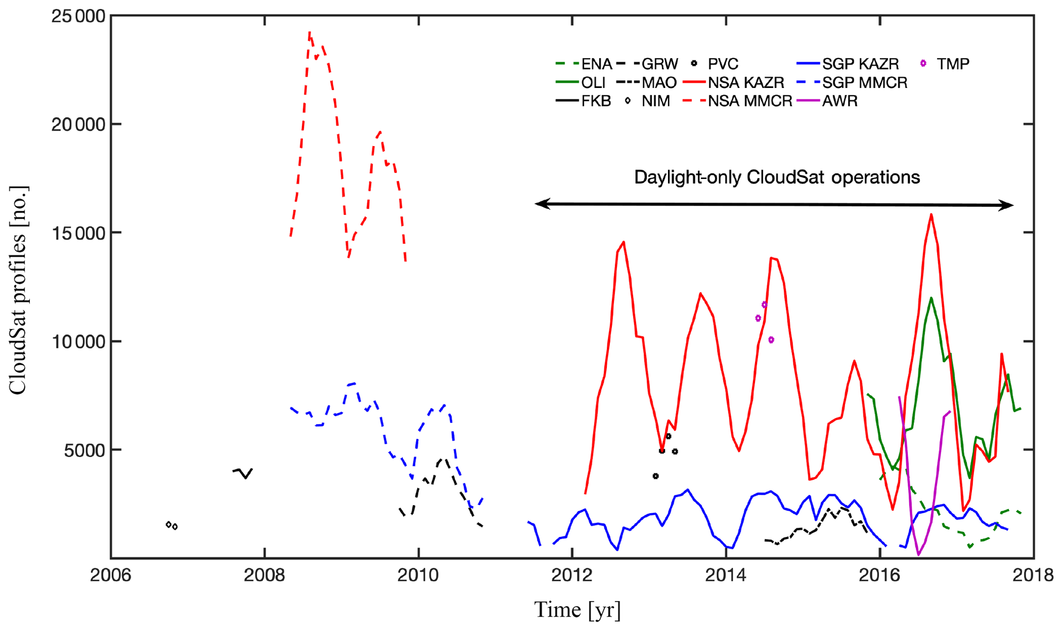
Figure 5The number of CloudSat profiles found within a ±3-month window suitable for calibrating the ARM cloud radars as a function of time for the different ARM sites.
A total of 653 ARM–CloudSat comparisons were performed using a running 6-month time window. The relationship between the minimum RMSE value achieved in a particular ARM–CloudSat comparison and the corresponding number of CloudSat columns is shown in Fig. 6. As expected, the RMSE value decreases with the number of samples. The analysis of the entire ARM–CloudSat comparison record suggests that when the number of CloudSat columns is less than 500, the comparison is difficult to perform. In addition to the value of RMSE and the number of CloudSat columns, the goodness of the fit between the ARM and CloudSat cloud top height pdf's is evaluated when the minimum RMSE is achieved. Out of the possible 653 calibration coefficients, 616 were accepted, i.e., a 94.3 % success rate.
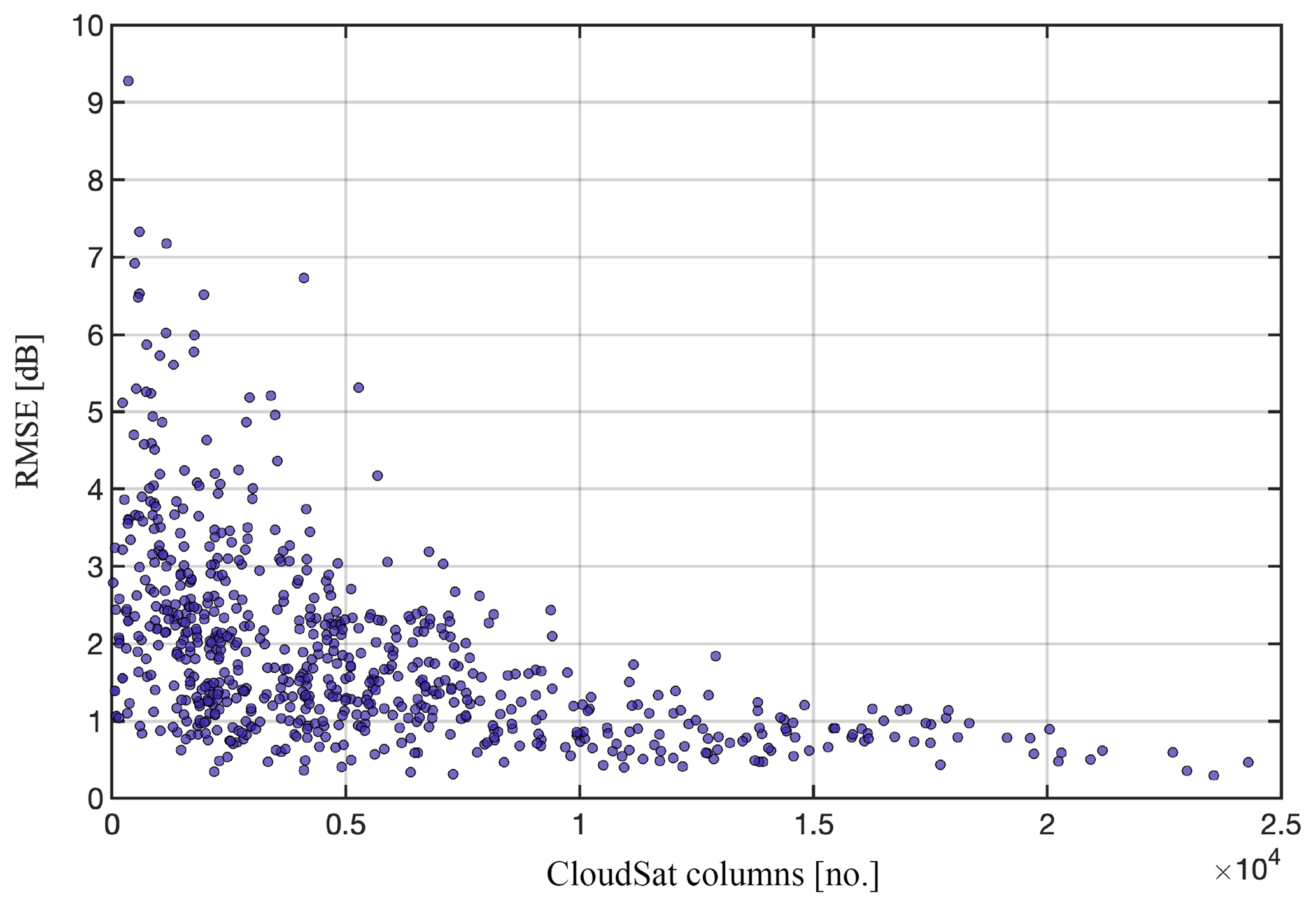
Figure 6The relationship between the minimum RMSE (dB) achieved in a particular ARM–CloudSat comparison and the corresponding number of CloudSat columns.
First, the results of the ARM–CloudSat comparison at the two sites that feature the most recently acquired profiling cloud radar systems of the ARM facility are discussed. The two KAZR2 systems are located at critical climatological locations (ENA and OLI) and are the primary sources of cloud observations. The OLI KAZR2 is compared against the CloudSat CPR for the period September 2015 to December 2017. Figure 7a shows the calibration offset (dB) we need to add to the MD mode observation to minimize the RMSE with the CloudSat observations. If the calibration offset is positive, this suggests that the MD mode underestimates the radar reflectivity compared to CloudSat. Although a 6-month running time window is used, considerable temporal variability is observed, especially at the beginning of the period. At the beginning of the period, −2.3 dB needs to be added to the ARM observations to statistically minimize their differences against the CloudSat observations. During the first 4 months of 2016, +3.4 to +4.6 dB needs to be added. The last estimate of this 4-month period is higher (+6.9 dB) and coincides with a period when considerable changes occurred in the radar hardware/software and the calibration offset is back to −2.3 dB. Through our analysis, every time the ARM radar hardware and/or software (including receiver signal processing) underwent a change, we noticed that the ARM–CloudSat comparison was challenging to achieve. This is attributed to the fact that part of the 6-month observing period uses observations with one configuration and the other part uses observations with a different configuration. After this period, the calibration offset changes, slowly increasing to +1–3 dB in early 2017, and during the latter part of 2017 the calibration offset is less than +0.5 dB.
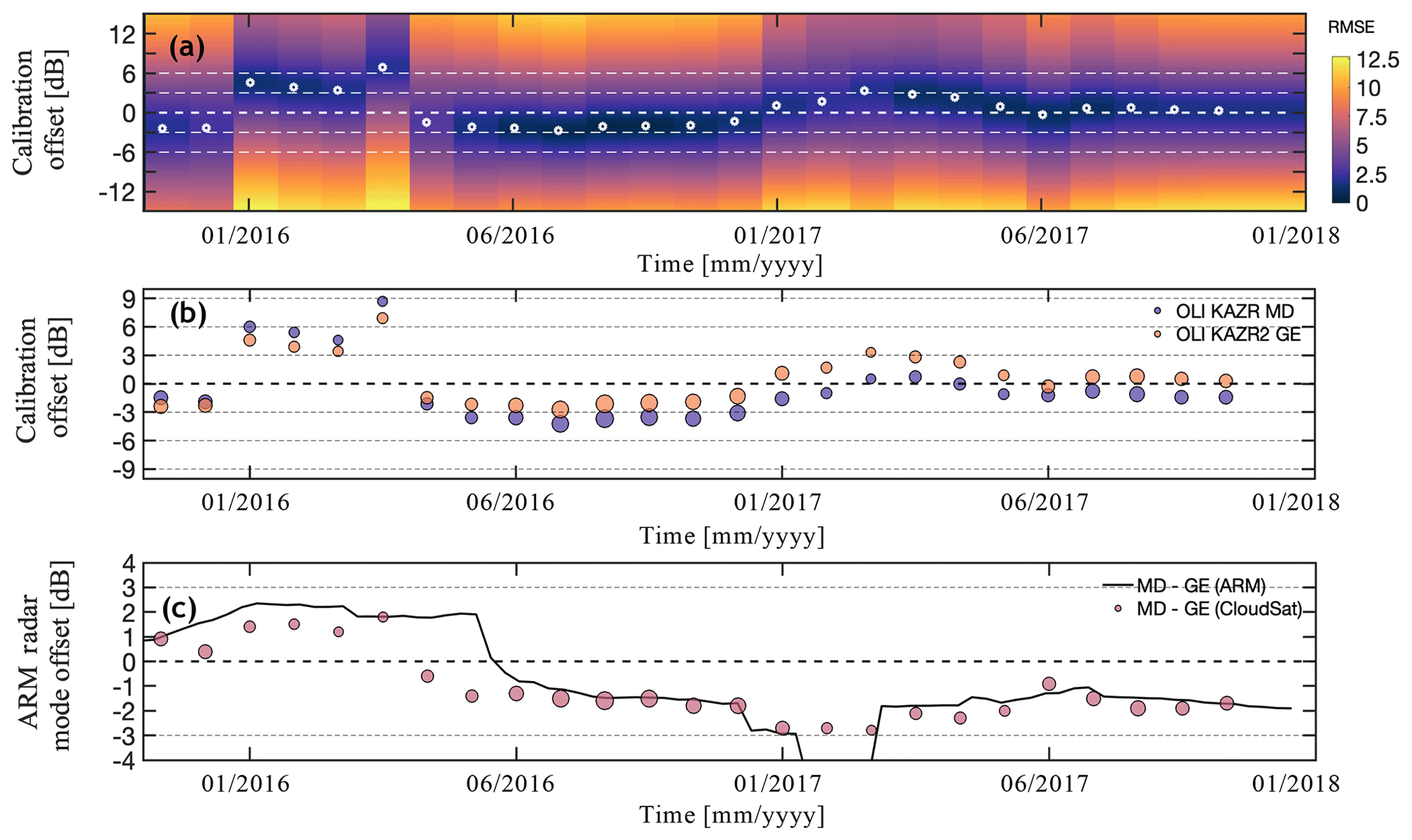
Figure 7(a) The OLI KAZR2 MD mode calibration offset as reported by the CloudSat–ARM comparison (circles). The colors indicate the RMSE of the CloudSat–ARM comparison for different radar calibration offsets. (b) The AMF3 (Oliktok Point, Alaska) KAZR2 MD and GE mode calibration offset as reported by the CloudSat–ARM comparison. The size of the circles indicates the ratio of the sample size of the CloudSat columns for any given calibration offset estimate relative to the maximum sample size of CloudSat columns observed during the same period by the same mode. (c) The difference between the MD–GE modes as reported by the CloudSat–ARM comparison and as reported by the comparison of ARM radar mode to ARM radar mode.
Figure 7b shows the calibration offset for both KAZR2 operating modes (MD and GE) using the ARM–CloudSat comparison methodology applied to the recorded radar reflectivities of each mode. Overall, the calibration offsets closely follow each other throughout the observing period. During the first 6 months, the calibration offset for the MD is about 1 dB higher, suggesting that the MD reported on average 1–2 dB lower radar reflectivities than the GE mode. This relationship is reversed around April 2016 and until the end of the observing period; the calibration offset for the MD mode is now 1–2 dB lower than that estimated for the GE mode. Noticeably, the reversal in relationship of the calibration offsets coincides with the period that we argued earlier coincides with changes in the radar configuration around April 2016. During that period, the number of fast Fourier transform (FFT) points in the recorded radar Doppler spectra changed from 256 to 512 and the calibration was updated (Joseph Hardin, ARM radar engineer, personal communication, 2018).
As discussed in Sect. 2.1 the ARM MD and GE mode observations can be used to estimate their relative offset. Figure 7c shows the difference (MD–GE) in decibels of the two KAZR2 operating modes (black line). On the same plot, the difference (MD–GE) in decibels as seen from CloudSat is also reported (circles). Overall, a very good agreement is found between the two estimates of the radar reflectivity offset between the two KAZR2 modes. This suggests that the ARM–CloudSat comparison can provide high-quality information regarding the absolute and relative calibration offsets between radar modes.
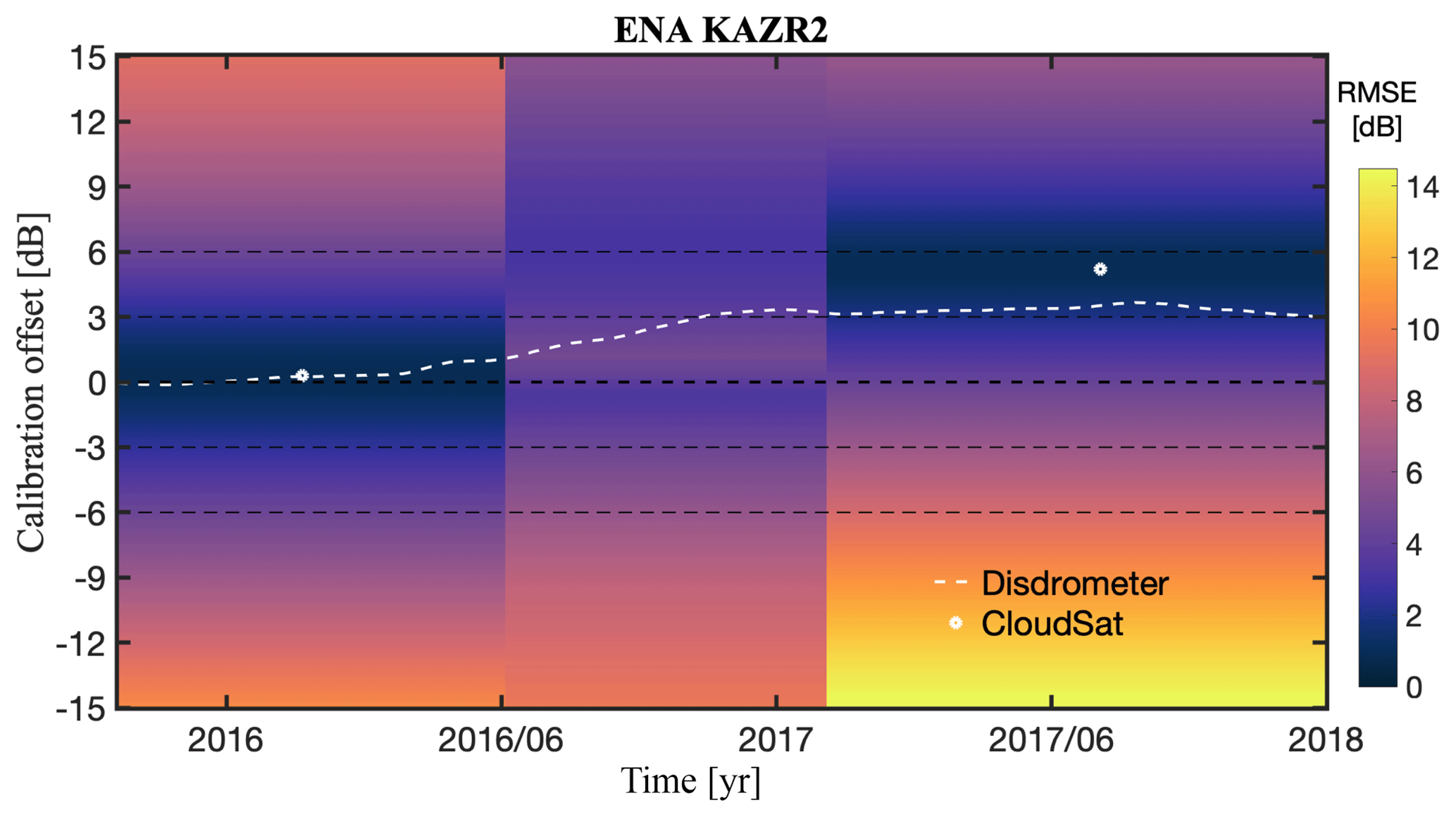
Figure 8The ENA KAZR2 calibration offset as reported by the CloudSat–ARM comparison (star symbol) and by the KAZR2 and Parsivel disdrometer comparison (line). The colors indicate the RMSE of the CloudSat–ARM comparison for different radar calibration offsets.
The second KAZR2 system has been operated at the ENA since the fall of 2015. Figure 8 shows two calibration offset (dB) values for the KAZR 2 MD (white symbols). Contrary to the OLI site, the ENA site cloud and temperature climatologies do not favor the collection of a large number of suitable CloudSat columns for calibration (Fig. 5). During the first 9 months of operation (October 2015–July 2016) the calibration offset was very small (+0.3 dB), indicating that the radar was well calibrated. During the last 10 months of the observing period (January–October 2017), the calibration offset is +5.2 dB. In an attempt to independently verify the observed trend in the KAZR2 calibration offset, the Parsivel disdrometer particle size distribution (PSD) measurements available at 1 min temporal resolution are used. The difference between the Parsivel-derived radar reflectivity and the KAZR2 radar reflectivity is shown in Fig. 8 (white dotted line) and suggests a trend, similar to the calibration offset estimated from the ARM–CloudSat comparison. Additional information regarding the estimation of the KAZR2 calibration offset using the Parsivel disdrometer can be found in Appendix A.
The ARM TWP Darwin, Manus, and Nauru sites are located deep in the tropics and featured MMCR systems until the first quarter of 2011. Only at two sites (Darwin and Manus), the MMCR systems replaced by KAZR systems. All TWP sites terminated operations in 2014 (Long et al., 2016). The calibration offsets for the period 2007 to 2014 at the TWP sites are shown in Fig. 9. The calibration offset record is not continuous since the number of CloudSat columns is affected by the significant inter- and intraseasonal cloud and precipitation variability driven by large-scale features at different temporal–spatial scales such as El Niño–Southern Oscillation, the Madden–Julian oscillation, and the movement of the intertropical convergence zone (ITCZ). The operational record of the TWP systems is also intermittent due to the logistical challenges associated with the physical presence of ARM engineers at these sites: delays associated with the delivery of hardware components at the TWP sites and poor communications for instrument monitoring, especially at Manus and Nauru (Long et al., 2016). Overall, the calibration offsets are within ±6 dB. The ARM intramode differences in the reported radar reflectivities are also reported (gray circles) to help interpret the estimated calibration offset trends. The Darwin MMCR exhibits the highest variability in the ARM intramode differences, suggesting frequent changes in the MMCR hardware and/or software. During these periods, no reliable ARM–CloudSat calibration offsets are estimated. Liu et al. (2009) compared radar reflectivity histograms from the Darwin MMCR and CloudSat and their analysis supports the suggestion that the MMCR calibration was low at Darwin in the 2006–2007 wet season. The Darwin KAZR GE calibration offset record is very sparse due to long periods with no observations. Noticeably, only GE mode observations are available at the Darwin and Manus sites. At Manus, the ARM intramode differences are small (less than 1 dB) and remain stable over a long period (3.5 years). As a result, we have calibration offset estimates for the entire observed period. The Manus MMCR 2 calibration offset gradually drifts from negative in 2007 to near zero for almost all 2008, increases to +7 dB in early 2009, and after the middle of 2009 to the end of its observational record slowly fluctuates by ±3 dB. The KAZR GE calibration record is also sparse with a small calibration offset during its early operation and a +5 dB offset during the late period of its operational record at Manus. Finally, the record of MMCR observations at Nauru that overlaps with CloudSat operations in space is short (1.5 year). During that period, the ARM intramode differences fluctuate between two stages (+1.5 dB and near 0 dB). The ARM–CloudSat calibration offsets also fluctuate temporally in a similar manner between two stages (+5–6 dB and 2–3 dB). No KAZR observations were conducted at Nauru.
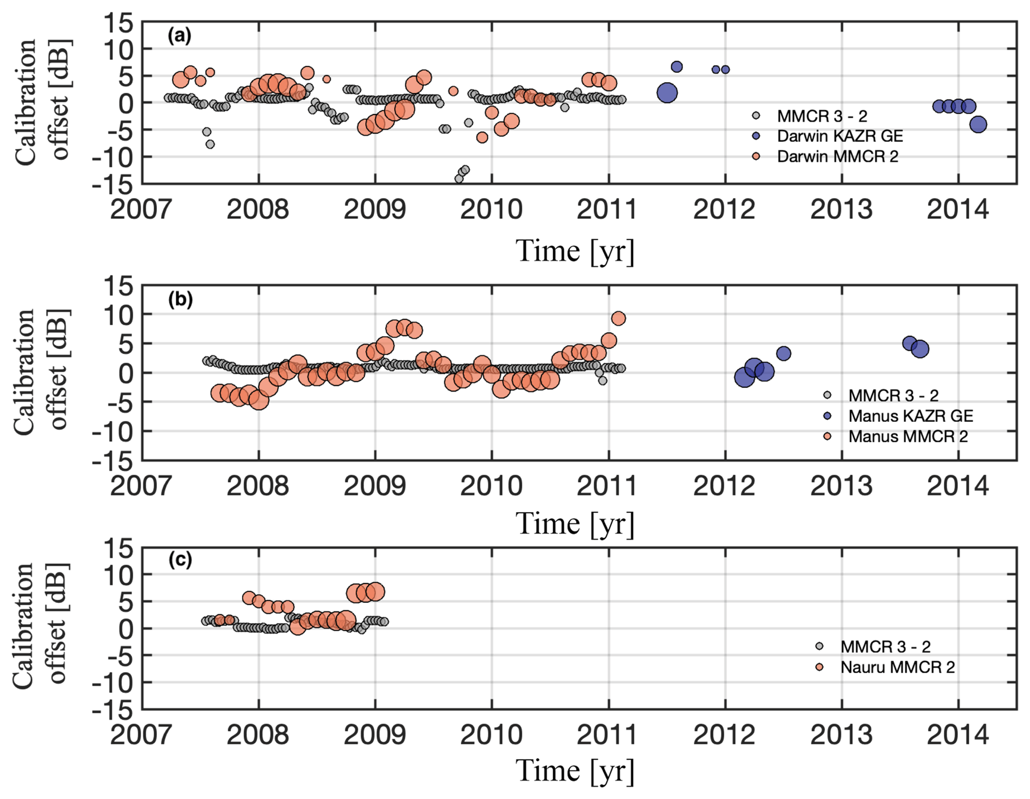
Figure 9The calibration offset for the MMCR mode 2 and KAZR GE mode at the Tropical Western Pacific (TWP) sites of (a) Darwin, (b) Manus, and (c) Nauru based on the ARM–CloudSat comparison. The size of the circles indicates the ratio of the sample size of the CloudSat columns for any given calibration offset estimate relative to the maximum sample size of CloudSat columns observed during the same period by the same mode. The gray circles indicate the ARM mode 3–mode 2 difference as estimated from the ARM radar mode intercomparison.
The ARM NSA and SGP sites are the two longest operating sites of the ARM facility (Sisterson et al., 2016; Verlinde et al., 2016). The NSA represents a typical Arctic environment with very low temperatures while the SGP has been the observational centerpiece and anchor of the ARM facility since 1992. The calibration offsets for the period 2008 to 2017 at these two sites along with the ARM intramode differences are shown in Fig. 10. The NSA MMCR 2 significantly overestimates the radar reflectivity, and a calibration offset between −4.4 and −8.4 dB (gradually increasing from 2008 to 2009) is required to minimize the RMSE when compared to CloudSat. This large calibration offset is consistent with the impact of corrosion on the waveguide that was attached to the antenna feed, effectively breaking the connection between the waveguide and the feed. This hardware failure went unobserved until it was accidently discovered during a system inspection (Kollias et al., 2016). During the same period, the ARM intramode difference (mode 3–mode 2) gradually increases from 0.8 to 2.5 dB. The NSA KAZR MD mode is compared to CloudSat for the period 2012 to 2017. During the first 2 years, the KAZR MD calibration offset is for the most part within ±1 dB, suggesting that the radar was well calibrated. During the 2014–2017 period, the KAZR MD mode calibration offset is between +3 and +6 dB and the ARM intramode (GE–MD) difference is around −1.7 dB. The SGP MMCR mode 2 calibration offset is significant during the period 2008–2011. In 2008 the calibration offset is between +7 and +10 dB, −3.5 and −4.5 dB in the early part of 2009, and +4 and +6 dB for remainder of the operating period of the MMCR at SGP. The ARM intramode difference (mode 3–mode 2) is for the most part between +0.5 and 0.9 dB. The SGP KAZR MD mode is compared to CloudSat for the period June 2011 to December 2017. The calibration offset values are positive (+3 to +6 dB) at the beginning and then negative (−1 to −6 dB) during the 2014–2017 period. The ARM intramode differences (GE–MD) are in the range of ±1 dB and small shifts in their magnitude and sign correlate with periods where the calibration offset changes.
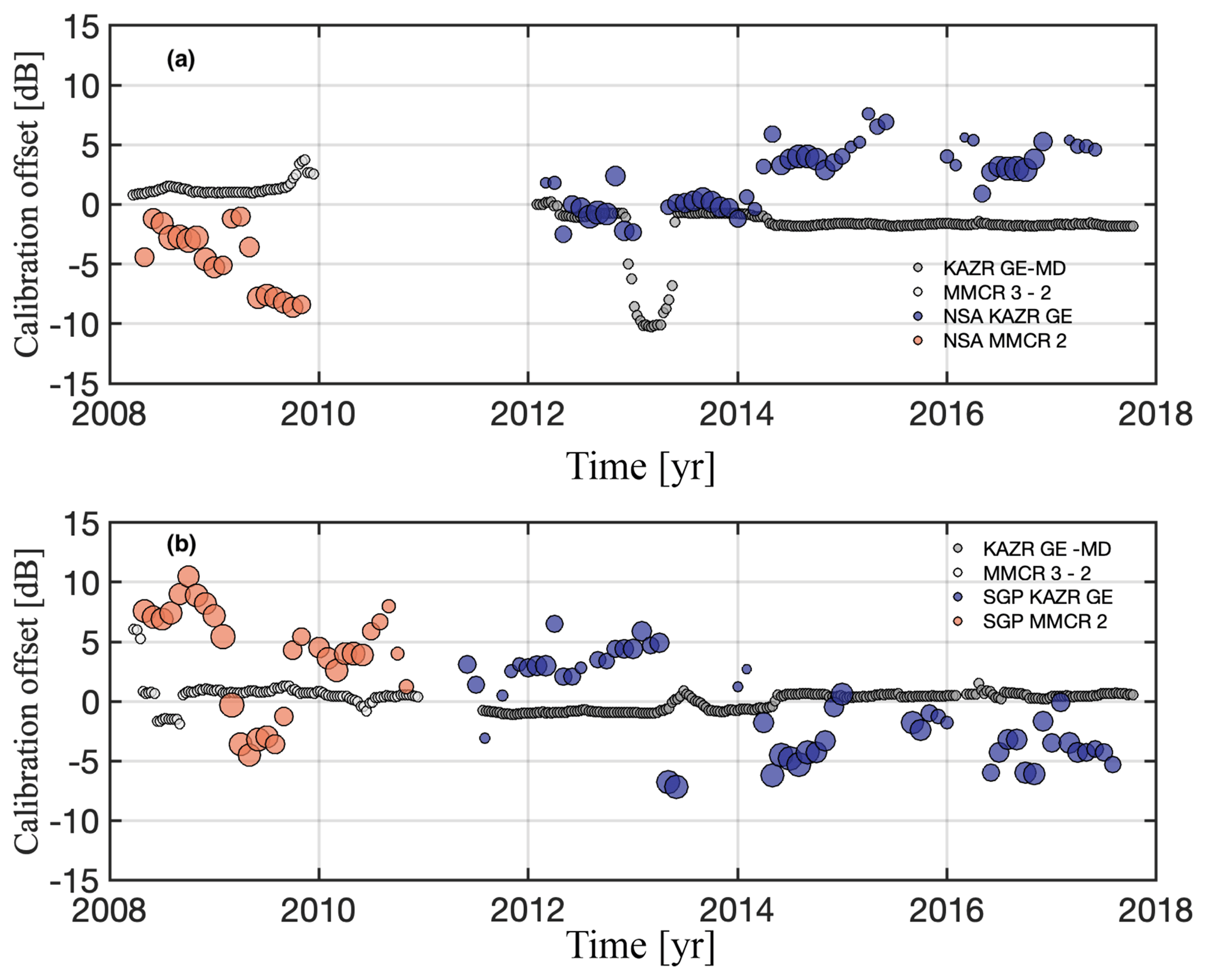
Figure 10The calibration offset for the MMCR mode 2 and KAZR GE mode at (a) NSA and (b) SGP sites based on the ARM–CloudSat comparison. The size of the circles indicates the ratio of the sample size of the CloudSat columns for any given calibration offset estimate relative to the maximum sample size of CloudSat columns observed during the same period by the same mode. The gray circles indicate the ARM MMCR mode 3–mode 2 and KAZR GE–MD mode difference as estimated from the ARM radar mode intercomparison.
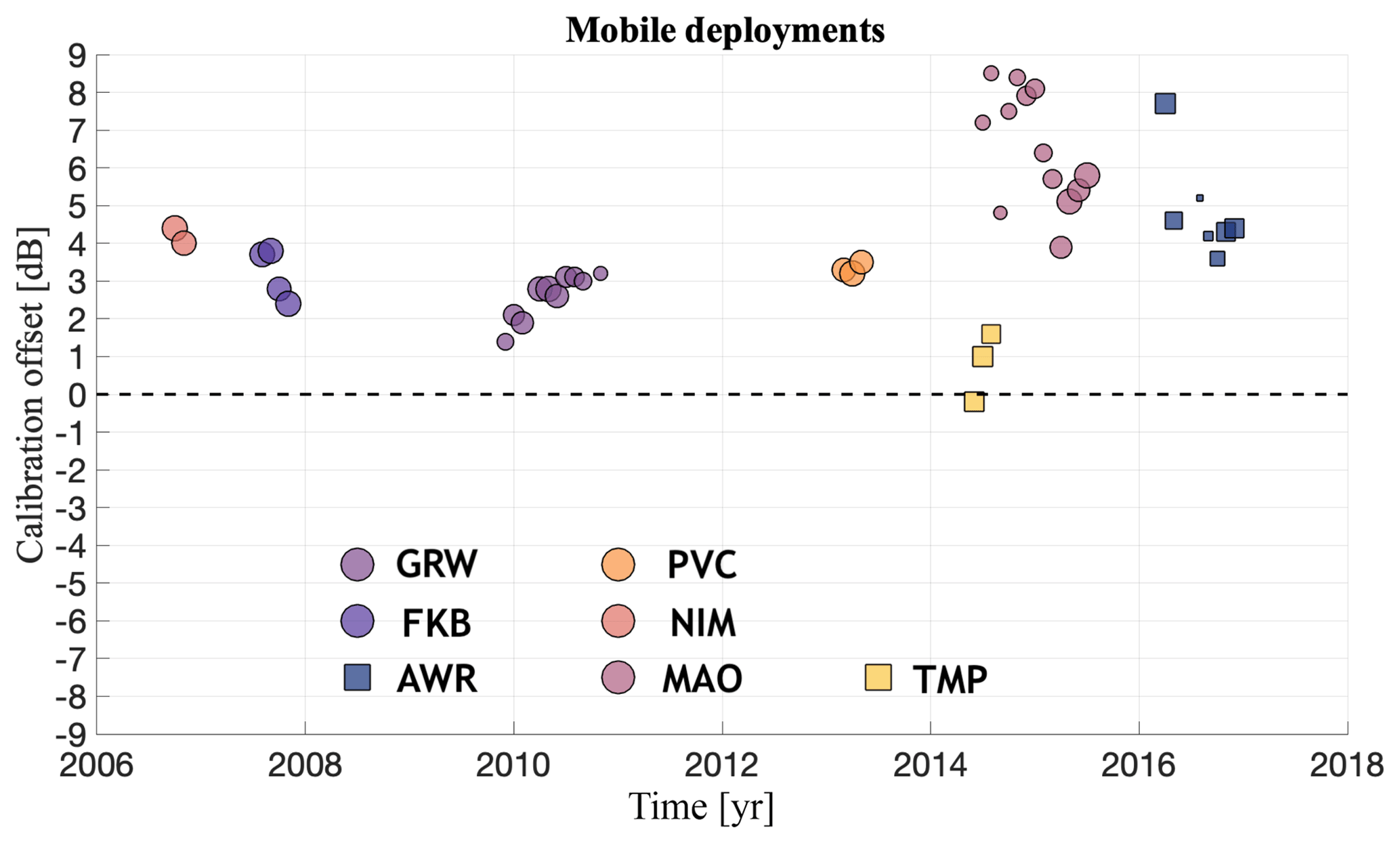
Figure 11The radar calibration offset we should add to the reported ARM cloud radar reflectivities in order to minimize their differences with those reported by the CloudSat CPR at the ARM Mobile Facility (AMF) sites. The size of the circles indicates the ratio of the sample size of the CloudSat columns for any given calibration offset estimate relative to the maximum sample size of CloudSat columns observed during the same period by the same mode. Circles correspond to 94 GHz (WACR) calibration offsets and squares correspond to 35 GHz (KAZR) calibration offsets.
The ARM Mobile Facility (AMF) is a portable atmospheric observatory equipped with a sophisticated suite of instruments designed to collect essential data from cloudy and clear atmospheres in important but under-sampled climatic regions. As such, the AMF deployments are often the only source for ground-based observations of clouds and precipitation at some of the AMF deployments (Miller et al., 2016). Here, we report the calibration offsets for five deployments of the first ARM Mobile Facility (AMF1) and two deployments of the second ARM Mobile Facility (AMF2). The results are shown in Fig. 11. The AMF1 deployments are Niger, west Africa (NIM); Black Forest, Germany (FKB); Graciosa island, Azores (GRW); Cape Cod, Massachusetts (PVC); and Manacaparu, Brazil (MAO) and the AMF2 deployments are Hyytiälä, Finland (TMP) and McMurdo Station, Antarctica (AWR). The AMF deployments are typically 1-year deployments, except for the GRW and MAO deployments that lasted for 2 years. At the AMF1 deployments the main profiling cloud radar system was the WACR and at the AMF2 deployments a KAZR. The short duration of the mobile deployments coupled with the time needed to relocate the AMFs to their next field location makes the AMF calibration offset record sparse. At NIM, the AMF deployment was over 13 months long but the WACR was deployed for only 8 months and two WACR calibration offsets are estimated (+4.4 and +4.0 dB). The following year, during the FKB AMF deployment, four WACR calibration offsets are estimated (+3.7, +3.8, +2.8, and 2.4 dB). During the 2-year deployment at GRW the WACR calibration offset started from a low value of +1.4 dB and gradually rose to +3.2 dB. At PVC, the WACR calibration offset was between +3.3 and +3.5 dB. During the same period, the WACR was also deployed in India and China; however, the short record of WACR observations during these deployments does not allow us to conduct ARM–CloudSat comparisons. Despite the large number of field deployments, the WACR calibration did not change a lot. However, during the 2-year MAO deployment, the estimated calibration offsets were higher and more variable (+3.9 to +8.5 dB).
The AMF2 was established later than the AMF1; thus, its deployment record is shorter. The AMF2 deployment in Hyytiälä, Finland (TMP), has been considered the first successful deployment of triple-frequency radar observations by the ARM facility (Kneifel et al., 2015) with well-calibrated radar systems. The ARM–CloudSat comparison confirms that the KAZR MD mode was well calibrated during the TMP deployment and the calibration offsets are −0.2, +1.0, and +1.6 dB (Fig. 11). During the most recent AMF2 deployment at McMurdo Station (AWR), significant calibration offset was found. Due to surrounding elevated topography, AWR is the only site where additional post-processing of the CloudSat observations was required to eliminate antenna side lobe contributions. In addition, the AWR high-latitude location in combination with the restriction of daylight-only CloudSat observations limited the number of available CloudSat samples, especially during the Southern Hemisphere winter (Fig. 5). As a result, most of the CloudSat samples are available at the beginning and the end of the field campaign. At the beginning, the calibration offset is +7.7 dB and during the latter part of the mobile deployment it is between +3.5 and +5.1 dB (Fig. 11). The ARM intramode difference (GE–MD) is −1.2 dB at the beginning of the period and −0.65 dB later in the deployment.
The DOE ARM facility has been at the forefront of the development and application of profiling and scanning millimeter-wavelength radars for over 20 years. The long record of ARM cloud radar observations represents a unique dataset that provides a bottom-up, high-resolution view of clouds and precipitation at a number of locations around the globe. The characterization of a decade-long cloud radar record from multiple locations is a necessary step for the development of unbiased statistics on cloud occurrence and the estimation of microphysical parameters using retrieval techniques. Once the characterization and reprocessing of the ARM radar observations is completed, the decade-long record and its added-value products can be used as observational targets for global climate model evaluation studies using suitable forward operators (Zhang et al., 2018; Lamer et al., 2018).
The use of CloudSat as a global calibrator for cloud radars was first proposed by Protat et al. (2011). Here, the Protat et al. (2011) technique is revised, improved, and automated and the entire record of CloudSat observations (2007–2017) is used to provide a calibration reference for over 43 years of ARM profiling cloud radar observations at fixed and mobile sites. Four generations of ARM cloud radar systems, operating at two different radar frequencies (35 and 94 GHz) are evaluated. All the radar systems (with the exception of the AMF1 WACR) operate using a sequence of modes with different capabilities in order to provide a uniform radar sensitivity and performance throughout the troposphere. The offsets in the reported radar reflectivity by these different modes for each radar are documented as a function of time. Abrupt changes in the offset magnitude and sign are found to correlate well with changes in the radar calibration as deduced by the statistical comparison with CloudSat. Thus, changes in the reflectivity offset between the modes should be monitored and used to identify periods where the calibration stability is suspect and moving forward perhaps trigger more prompt additional external calibration evaluations. Furthermore, the geographical location, the seasonal variability of the clouds and precipitation occurrence, and the operational status of the CloudSat CPR significantly affect the number of samples available within a 6-month time window to perform the ARM–CloudSat comparison. When the number of CloudSat columns is fewer than 500–1000, the comparison is difficult to perform. Out of the possible 653 calibration coefficients, 616 were accepted, i.e., a 94.3 % success rate.
The analysis demonstrates that both historic (i.e., MMCR) and recent ARM radar operations (i.e., KAZR2) require considerable adjustments before they can be used in a quantitative way. The analysis from Protat et al. (2011) and the experience gained in this study using the technique in a much larger dataset suggest that the accuracy of the CloudSat-based calibration of ground-based cloud radar systems is accurate within 1–2 dB. In most cases, the observed calibration offsets exceeded this uncertainty value, suggesting that the ARM profiling radar record contains considerable calibration biases. The reported calibration biases are expected to have a large impact on routine ARM microphysical data products such as the Continuous Baseline Microphysical Retrieval (MICROBASE) value-added product (Zhao et al., 2012). In addition, cloud retrieval techniques and associated products are impacted by the reported calibration offsets (Shupe et al., 2015; Dong et al., 2014). For reference, a 3 dB calibration offset is equivalent to a factor of 2 bias in hydrometeor content or number concentration retrievals. As part of the outcome of this study, the estimated calibration offsets, the RMSEs, and the number of samples as a function of time for each radar system evaluated here have been provided to the ARM facility. The ARM facility is currently considering reprocessing of the ARM radar record with these new calibration offsets. Furthermore, the gradual temporal change in the observed calibration offsets and the correlation of large swings in the calibration offset with periods when the ARM radar hardware and/or software was not operating in an optimal way suggest that the use of CloudSat can provide reliable information that can be used to characterize the calibration of ground-based radar systems.
Planned and future spaceborne radar systems such as the Earth Clouds Aerosols and Radiation Explorer (EarthCARE; Illingworth et al., 2015; Kollias et al., 2018) or future spaceborne radar concepts (Tanelli et al., 2018) will provide similar spaceborne radar measurements to evaluate large profiling cloud radar networks (e.g., ARM, ACTRIS) in the future. A project website that describes the ARM–CloudSat comparison at all the ARM sites and radar systems is now available to the entire user community: http://doppler.somas.stonybrook.edu/CloudSat_GlobalCalibrator/index.html (last access: 9 September 2019). The website contains graphics and animations that show the convergence of the radar reflectivity profiles and cloud top height distributions as a function of the calibration offset. In addition, the temporal evolution of the calibration offsets and the ARM radar mode differences are shown. In the future, the website will be updated to include future ARM fixed and mobile deployments and will also include a similar analysis for the European cloud radar network (ACTRIS).
Finally, there is merit in extending the presented analysis to other satellite measurements. For example, NASA's Global Precipitation Mission (GPM) Dual-Frequency Precipitation Radar (DPR) observations could be used in a similar manner to evaluate the calibration of the ARM facility centimeter-wavelength radars (Lamer et al., 2019). In addition to radar calibration, the statistical comparison between cloud and precipitation properties such as cloud base height, cloud thickness, precipitation occurrence and intensity, and liquid water path measured at the ARM facility and those derived by research satellites such as NASA'S A-Train constellation (Stephens et al., 2018) should be considered. The ARM facility provides a bottom-up view of clouds and precipitation with superior vertical resolution, especially in the boundary layer. Statistically significant differences with the top-down view provided by the A-Train satellites should be considered when conducting cloud-scale process studies using global satellite datasets.
The code used for the ARM–CloudSat comparison can be made available upon request. The ARM data were obtained from the Atmospheric Radiation Measurement (ARM) user facility, a U.S. Department of Energy (DOE) Office of Science user facility managed by the office of Biological and Environmental Research (BER). The CloudSat observations are available at the CloudSat Data Processing Center.
The use of surface-based measurements of the raindrop PSD using impact or optical disdrometers to calibrate profiling and scanning precipitation radars is not new. This technique has been widely used in the past for calibrating profiling centimeter-wavelength Doppler radars (Gage et al., 2000; Tridon et al., 2013). In the case of centimeter-wavelength radars, wet radome or antenna attenuation is negligible, the systems are configured to have sufficient dynamic range to detect intense precipitation returns without receiver saturation, and the Rayleigh scattering approximation is valid in most cases. At millimeter-wavelength radars, several factors need to be considered: the wet radome can induce considerable attenuation, at high rain rates the Rayleigh scattering approximation is not valid, and receiver saturation occurs at lower rain rates. Here, we use the Parsivel2 disdrometer (OTT Hydromet GmbH) measurements. The disdrometer provides 1 min averaged raindrop PSDs. From the Parsivel2 files, the variable “equivalent_radar_reflectivity”, which is the radar reflectivity calculated by the ARM ingest, is used. All 1 min Parsivel measurements where raindrops with a diameter > 4.5 mm are detected are filtered out to avoid the impact of false detection of large raindrops in the Parsivel2–KAZR2 comparison. The Parsivel2 time assigned to each data point indicates the beginning of a 1 min period of averaging. Using this time, 1 min averages of the KAZR2 reflectivities in linear units are estimated. Next, the KAZR2 radar reflectivities are corrected for path attenuation induced by the hydrometeor. The relationship is used to estimate the one-way attenuation at the Ka band (Matrosov, 2005). Only the 1 min data when the Parsivel2 radar reflectivity is between 0 and 20 dBZ are used. The lower limit is used to ensure that the Parsivel2 samples enough raindrops. The upper limit is used to minimize the impact of wet radome attenuation and to ensure that the Parsivel2 radar reflectivity estimates using the Rayleigh scattering approximation have no or negligible non-Rayleigh effects. The KAZR2 and Parsivel2 radar reflectivity time series were investigated for possible time lag; however, given the proximity of the radar data to the ground, no significant time lag was found. Finally using a running time window of 90 d, the mean of the differences of the KAZR2 and Parsivel2 radar reflectivities is estimated.

Figure A1(a) The calibration offset between the KAZR2 and Parsivel2 estimated using KAZR2 measurements from difference range gates (from the third to the 20th), (b) the calibration offset for the period 1 to 6 January 2016 using the eighth KAZR2 range gate, and (c) the calibration offset for the period 1 to 10 January 2017 using the eighth KAZR2 range gate. These two periods correspond to the periods used for the ARM–CloudSat calibration offsets shown in Fig. 8.
Figure A1a shows the time series of the calibration offset between the Parsivel2 and the KAZR2 for different KAZR2 range gates. In general, the calibration offset is positive, thus implying that the KAZR2 underestimates the radar reflectivity. However, the calibration offset varies a lot with the range gate. The KAZR2 is a pulsed radar; thus after each pulse transmission the receiver protection circuit (T/R switch network) needs to switch from transmit (closed receiver) to receive (open receiver) mode. The switch takes several hundreds of nanoseconds; thus, the KAZR2 returns from the first range gates (3 to 7) report lower radar reflectivity values, resulting in higher radar calibration offset values. Our analysis identified range gate 8 (240 m) as the closest range gate to the surface that is unaffected by the KAZR2 T/R switch network. Above range gate 8, the calibration offset continues to decrease, highlighting the impact of the evaporation on modifying the raindrop PSD. The scatter plots between the KAZR2 radar reflectivity at range gate 8 and the Parsivel2 radar reflectivities during the two extensive periods are shown in Fig. A1b, c. These two periods match the periods used to estimate calibration offsets using the ARM–CloudSat comparison technique (Fig. 8). The ARM–CloudSat comparison indicated calibration offsets of 0.3 and 5.2 dB and the ARM–Parsivel2 comparison indicated calibration offsets of 0.57 and 3.91 dB.
Disdrometers certainly have the potential to monitor the calibration of profiling cloud radars and this topic warrants additional analysis using comprehensive datasets from different cloud radar systems and for different climatological conditions. For example, frequency-modulated continuous-wave (FMCW) radars (Küchler et al., 2017) do not have T/R switch networks, but careful analysis is required to ensure proper alignment of the two antennas or correction for the antenna parallax problem (Sekelsky and Clothiaux, 2002). Furthermore, careful analysis is required to avoid using radar returns that saturate the radar receiver, especially at short ranges, and to account for non-Rayleigh scattering in the case of 94 GHz radar systems. This careful analysis is beyond the scope of this study.
PK designed the ARM–CloudSat comparison project, wrote the paper, and prepared most of the figures. BPT carried out all the coding for the ARM–CloudSat comparison and provided edits to the paper. AP provided his original code that was used in a previous publication to conduct a similar study and provided assistance and comments during the coding phase.
The authors declare that they have no conflict of interest.
Pavlos Kollias and Bernat Puigdomènech Treserras were supported by the U.S. DOE ARM and ASR radar science project. The authors would like to thank Jim Mather, Bradley Isom, and Joseph Hardin for reviewing the paper and providing valuable feedback.
This research has been supported by the U.S. Department of Energy, Office of Science (grant no. DE-SC0012704).
This paper was edited by Mark Kulie and reviewed by Roger Marchand and two anonymous referees.
Atlas, D.: Radar calibration: Some simple approaches, B. Am. Meteorol. Soc., 83, 1313–1316, 2002.
Bolen, S. M. and Chandrasekar, V.: Quantitative cross validation of space-based and ground-based radar observations, J. Appl. Meteorol., 39, 2071–2079, 2000.
Clothiaux, E. E., Miller, M. A., Perez, R. C., Turner, D. D., Moran, K. P., Martner, B. E., Ackerman, T. P., Mace, G. G., Marchand, R. T., and Widener, K. B.: The ARM millimeter wave cloud radars (MMCRs) and the active remote sensing of clouds (ARSCL) value added product (VAP), DOE Tech Memo. ARM VAP-002.1, 2001.
Dong, X., Xi, B., Kennedy, A., Minnis, P., and Wood, R.: A 19-month Marine Aerosol-Cloud_Radiation Properties derived from DOE ARM AMF deployment at the Azores: Part I: Cloud fraction and single-layered MBL cloud properties, J. Climate, 27, 3665–3682, doi:10.1175/JCLI-D-13-00553.1, 2014.
Gage, K. S., Williams, C. R., Johnston, P. E., Ecklund, W. L., Cifelli, R., Tokay, A., and Carter, D. A.: Doppler radar profilers as calibration tools for scanning radars, J. Appl. Meteorol., 39, 2209–2222, 2000.
Illingworth, A. J., Barker, H., Beljaars, A., Ceccaldi, M., Chepfer, H., Clerbaux, N., Cole, J., Delanoë, J., Domenech, C., and Donovan, D. P.: The EarthCARE satellite: The next step forward in global measurements of clouds, aerosols, precipitation, and radiation, B. Am. Meteorol. Soc., 96, 1311–1332, 2015.
Kneifel, S., Lerber, A., Tiira, J., Moisseev, D., Kollias, P., and Leinonen, J.: Observed relations between snowfall microphysics and triple-frequency radar measurements, J. Geophys. Res.-Atmos., 120, 6034–6055, 2015.
Kollias, P., Albrecht, B. A., Clothiaux, E. E., Miller, M. A., Johnson, K. L., and Moran, K. P.: The Atmospheric Radiation Measurement program cloud profiling radars: An evaluation of signal processing and sampling strategies, J. Atmos. Ocean. Tech., 22, 930–948, 2005.
Kollias, P., Clothiaux, E., Miller, M., Albrecht, B., Stephens, G., and Ackerman, T.: Millimeter-wavelength radars: New frontier in atmospheric cloud and precipitation research, B. Am. Meteorol. Soc., 88, 1608–1624, 2007a.
Kollias, P., Miller, M. A., Luke, E. P., Johnson, K. L., Clothiaux, E. E., Moran, K. P., Widener, K. B., and Albrecht, B. A.: The Atmospheric Radiation Measurement Program cloud profiling radars: Second-generation sampling strategies, processing, and cloud data products, J. Atmos. Ocean. Tech., 24, 1199–1214, 2007b.
Kollias, P., Bharadwaj, N., Widener, K., Jo, I., and Johnson, K.: Scanning ARM cloud radars, Part I: Operational sampling strategies, J. Atmos. Ocean. Tech., 31, 569–582, 2014a.
Kollias, P., Tanelli, S., Battaglia, A., and Tatarevic, A.: Evaluation of EarthCARE cloud profiling radar Doppler velocity measurements in particle sedimentation regimes, J. Atmos. Ocean. Tech., 31, 366–386, 2014b.
Kollias, P., Clothiaux, E. E., Ackerman, T. P., Albrecht, B. A., Widener, K. B., Moran, K. P., Luke, E. P., Johnson, K. L., Bharadwaj, N., and Mead, J. B.: Development and applications of ARM millimeter-wavelength cloud radars, Meteor. Mon., 57, 17.11–17.19, 2016.
Kollias, P., Battaglia, A., Tatarevic, A., Lamer, K., Tridon, F., and Pfitzenmaier, L.: The EarthCARE cloud profiling radar (CPR) doppler measurements in deep convection: challenges, post-processing, and science applications, Proc. SPIE, 2018, 107760R, https://doi.org/10.1117/12.2324321, 2018.
Küchler, N., Kneifel, S., Löhnert, U., Kollias, P., Czekala, H., and Rose, T.: A W-Band Radar–Radiometer System for Accurate and Continuous Monitoring of Clouds and Precipitation, J. Atmos. Ocean. Tech., 34, 2375–2392, 2017.
Lamer, K., Fridlind, A. M., Ackerman, A. S., Kollias, P., Clothiaux, E. E., and Kelley, M.: (GO)2-SIM: a GCM-oriented ground-observation forward-simulator framework for objective evaluation of cloud and precipitation phase, Geosci. Model Dev., 11, 4195–4214, https://doi.org/10.5194/gmd-11-4195-2018, 2018.
Li, L., Heymsfield, G. M., Tian, L., and Racette, P. E.: Measurements of ocean surface backscattering using an airborne 94 GHz cloud radar – Implication for calibration of airborne and spaceborne W-band radars, J. Atmos. Ocean. Tech., 22, 1033–1045, 2005.
Liebe, H. M.: MPM – An atmospheric millimeter-wave propagation model, Int. J. Infra. Mill. Waves, 10, 631–650, 1989.
Liu, Z., Marchand, R., and Ackerman, T.: A comparison of observations in the tropical western Pacific from ground‐based and satellite millimeter‐wavelength cloud radars, J. Geophys. Res., 115, D24206, doi:10.1029/2009JD013575, 2010.
Long, C., Mather, J., and Ackerman, T.: The ARM Tropical Western Pacific (TWP) sites, Meteor. Mon., 57, 7.1–7.14, 2016.
Mather, J. H. and Voyles, J. W.: The ARM Climate Research Facility: A review of structure and capabilities, B. Am. Meteorol. Soc., 94, 377–392, 2013.
Matrosov, S. Y.: Attenuation-based estimates of rainfall rates aloft with vertically pointing Ka-band radars, J. Atmos. Ocean. Tech., 22, 43–54, 2005.
Miller, M., Nitschke, K., Ackerman, T., Ferrell, W., Hickmon, N., and Ivey, M.: The ARM mobile facilities, Meteor. Mon., 57, 9.1–9.15, 2016.
Moran, K. P., Martner, B. E., Post, M., Kropfli, R. A., Welsh, D. C., and Widener, K. B.: An unattended cloud-profiling radar for use in climate research, B. Am. Meteorol. Soc., 79, 443–456, 1998.
North, K. W., Oue, M., Kollias, P., Giangrande, S. E., Collis, S. M., and Potvin, C. K.: Vertical air motion retrievals in deep convective clouds using the ARM scanning radar network in Oklahoma during MC3E, Atmos. Meas. Tech., 10, 2785–2806, https://doi.org/10.5194/amt-10-2785-2017, 2017.
Protat, A., Delanoë, J., O'Connor, E., and L'Ecuyer, T.: The evaluation of CloudSat and CALIPSO ice microphysical products using ground-based cloud radar and lidar observations, J. Atmos. Ocean. Tech., 27, 793–810, 2010.
Protat, A., Bouniol, D., O'Connor, E., Klein Baltink, H., Verlinde, J., and Widener, K.: CloudSat as a global radar calibrator, J. Atmos. Ocean. Tech., 28, 445–452, 2011.
Rosenkranz, P. W.: Water vapor microwave continuum absorption: A comparison of measurements and models, Radio Sci., 33, 919–928, 1998.
Sekelsky, S. M. and Clothiaux, E. E.: Parallax errors and corrections for dual-antenna millimeter-wave cloud radars, J. Atmos. Ocean. Tech., 19, 478–485, 2002.
Shupe, M. D., Turner, D. D., Zwink, A., Thieman, M. M., Mlawer, E. J., and Shippert, T.: Deriving Arctic Cloud Microphysics at Barrow, Alaska: Algorithms, Results, and Radiative Closure, J. Appl. Meteor. Climatol., 54, 1675–1689, https://doi.org/10.1175/JAMC-D-15-0054.1, 2015.
Sisterson, D., Peppler, R., Cress, T., Lamb, P., and Turner, D.: The ARM southern great plains (SGP) site, Meteor. Mon., 57, 6.1–6.14, 2016.
Stephens, G., Winker, D., Pelon, J., Trepte, C., Vane, D., Yuhas, C., L'ecuyer, T., and Lebsock, M.: CloudSat and CALIPSO within the A-Train: ten years of actively observing the Earth system, B. Am. Meteorol. Soc., 99, 569–581, 2018.
Tanelli, S., Durden, S. L., Im, E., Pak, K. S., Reinke, D. G., Partain, P., Haynes, J. M., and Marchand, R. T.: CloudSat's cloud profiling radar after two years in orbit: Performance, calibration, and processing, IEEE T. Geosci. Remote, 46, 3560–3573, 2008.
Tridon, F., Battaglia, A., Kollias, P., Luke, E., and Williams, C. R.: Signal postprocessing and reflectivity calibration of the atmospheric radiation measurement program 915-MHz wind profilers, J. Atmos. Ocean. Tech., 30, 1038–1054, 2013.
Verlinde, J., Zak, B., Shupe, M., Ivey, M., and Stamnes, K.: The arm north slope of alaska (nsa) sites, Meteor. Mon., 57, 8.1–8.13, 2016.
Zhang, Y., Xie, S., Klein, S. A., Marchand, R., Kollias, P., Clothiaux, E. E., Lin, W., Johnson, K., Swales, D., and Bodas-Salcedo, A.: The ARM Cloud Radar Simulator for Global Climate Models: Bridging Field Data and Climate Models, B. Am. Meteorol. Soc., 99, 21–26, 2018.